EP1056237A2 - Détection en diversité pour WCDMA - Google Patents
Détection en diversité pour WCDMA Download PDFInfo
- Publication number
- EP1056237A2 EP1056237A2 EP00107130A EP00107130A EP1056237A2 EP 1056237 A2 EP1056237 A2 EP 1056237A2 EP 00107130 A EP00107130 A EP 00107130A EP 00107130 A EP00107130 A EP 00107130A EP 1056237 A2 EP1056237 A2 EP 1056237A2
- Authority
- EP
- European Patent Office
- Prior art keywords
- synchronization code
- base station
- time
- data signal
- circuit
- Prior art date
- Legal status (The legal status is an assumption and is not a legal conclusion. Google has not performed a legal analysis and makes no representation as to the accuracy of the status listed.)
- Granted
Links
Images


Classifications
-
- H—ELECTRICITY
- H04—ELECTRIC COMMUNICATION TECHNIQUE
- H04B—TRANSMISSION
- H04B1/00—Details of transmission systems, not covered by a single one of groups H04B3/00 - H04B13/00; Details of transmission systems not characterised by the medium used for transmission
- H04B1/69—Spread spectrum techniques
- H04B1/707—Spread spectrum techniques using direct sequence modulation
- H04B1/7073—Synchronisation aspects
-
- H—ELECTRICITY
- H04—ELECTRIC COMMUNICATION TECHNIQUE
- H04B—TRANSMISSION
- H04B7/00—Radio transmission systems, i.e. using radiation field
- H04B7/02—Diversity systems; Multi-antenna system, i.e. transmission or reception using multiple antennas
- H04B7/04—Diversity systems; Multi-antenna system, i.e. transmission or reception using multiple antennas using two or more spaced independent antennas
- H04B7/06—Diversity systems; Multi-antenna system, i.e. transmission or reception using multiple antennas using two or more spaced independent antennas at the transmitting station
- H04B7/0613—Diversity systems; Multi-antenna system, i.e. transmission or reception using multiple antennas using two or more spaced independent antennas at the transmitting station using simultaneous transmission
- H04B7/0667—Diversity systems; Multi-antenna system, i.e. transmission or reception using multiple antennas using two or more spaced independent antennas at the transmitting station using simultaneous transmission of delayed versions of same signal
-
- H—ELECTRICITY
- H04—ELECTRIC COMMUNICATION TECHNIQUE
- H04L—TRANSMISSION OF DIGITAL INFORMATION, e.g. TELEGRAPHIC COMMUNICATION
- H04L1/00—Arrangements for detecting or preventing errors in the information received
- H04L1/02—Arrangements for detecting or preventing errors in the information received by diversity reception
- H04L1/06—Arrangements for detecting or preventing errors in the information received by diversity reception using space diversity
- H04L1/0618—Space-time coding
- H04L1/0631—Receiver arrangements
-
- H—ELECTRICITY
- H04—ELECTRIC COMMUNICATION TECHNIQUE
- H04B—TRANSMISSION
- H04B1/00—Details of transmission systems, not covered by a single one of groups H04B3/00 - H04B13/00; Details of transmission systems not characterised by the medium used for transmission
- H04B1/69—Spread spectrum techniques
- H04B1/707—Spread spectrum techniques using direct sequence modulation
- H04B1/7097—Interference-related aspects
- H04B1/711—Interference-related aspects the interference being multi-path interference
- H04B1/7115—Constructive combining of multi-path signals, i.e. RAKE receivers
- H04B1/7117—Selection, re-selection, allocation or re-allocation of paths to fingers, e.g. timing offset control of allocated fingers
-
- H—ELECTRICITY
- H04—ELECTRIC COMMUNICATION TECHNIQUE
- H04L—TRANSMISSION OF DIGITAL INFORMATION, e.g. TELEGRAPHIC COMMUNICATION
- H04L25/00—Baseband systems
- H04L25/02—Details ; arrangements for supplying electrical power along data transmission lines
- H04L25/0202—Channel estimation
- H04L25/0204—Channel estimation of multiple channels
-
- H—ELECTRICITY
- H04—ELECTRIC COMMUNICATION TECHNIQUE
- H04L—TRANSMISSION OF DIGITAL INFORMATION, e.g. TELEGRAPHIC COMMUNICATION
- H04L25/00—Baseband systems
- H04L25/02—Details ; arrangements for supplying electrical power along data transmission lines
- H04L25/0202—Channel estimation
- H04L25/0224—Channel estimation using sounding signals
- H04L25/0228—Channel estimation using sounding signals with direct estimation from sounding signals
- H04L25/023—Channel estimation using sounding signals with direct estimation from sounding signals with extension to other symbols
Definitions
- This invention relates to wideband code division multiple access (WCDMA) for a communication system and more particularly to modulation of primary or secondary synchronization codes to indicate space-time transmit diversity for WCDMA signals.
- WCDMA wideband code division multiple access
- CDMA code division multiple access
- FDMA frequency division multiple access
- TDMA time division multiple access
- WCDMA wideband code division multiple access
- These WCDMA systems are coherent communications systems with pilot symbol assisted channel estimation schemes. These pilot symbols are transmitted as quadrature phase shift keyed (QPSK) known data in predetermined time frames to any receivers within range.
- QPSK quadrature phase shift keyed
- the frames may propagate in a discontinuous transmission (DTX) mode.
- DTX discontinuous transmission
- voice traffic transmission of user data occurs when the user speaks, but no data symbol transmission occurs when the user is silent.
- packet data the user data may be transmitted only when packets are ready to be sent.
- the frames are subdivided into fifteen equal time slots of 0.67 milliseconds each.
- Each time slot is farther subdivided into equal symbol times.
- each time slot includes twenty symbol times.
- Each frame includes pilot symbols as well as other control symbols such as transmit power control (TPC) symbols and rate information (RI) symbols. These control symbols include multiple bits otherwise known as chips to distinguish them from data bits.
- TPC transmit power control
- RI rate information
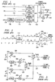
- FIG. 1 there is a simplified block diagram of a typical transmitter using Space-Time Transit Diversity (STTD) of the prior art.
- the transmitter circuit receives pilot symbols, TPC symbols, RI symbols and data symbols on leads 100, 102, 104 and 106, respectively.
- Each of the symbols is encoded by a respective STTD encoder.
- Each STTD encoder produces two output signals that are applied to multiplex circuit 120.
- the multiplex circuit 120 produces each encoded symbol in a respective symbol time of a frame.
- a serial sequence of symbols in each frame is simultaneously applied to each respective multiplier circuit 124 and 126.
- a channel orthogonal code C m is multiplied by each symbol to provide a unique signal for a designated receiver.
- the STTD encoded frames are then applied to antennas 128 and 130 for transmission.
- FIG. 2 there is a block diagram showing signal flow in an STTD encoder of the prior art tat may be used with the transmitter of FIG. 1 for pilot symbol encoding.
- the pilot symbols are predetermined control signals that may be used for channel estimation and other functions.
- the encoding pattern of STTD encoder 112 is given in TABLE I.
- the STTD encoder receives pilot symbol 11 at symbol time T , pilot symbol S 1 at symbol time 2T , pilot symbol 11 at symbol time 3T and pilot symbol S 2 at symbol time 4T on lead 100 for each of sixteen time slots of a frame.
- the encoder has an exemplary data rate of 32 KSPS and produces a sequence of four pilot symbols for each of two antennas corresponding to leads 204 and 206, respectively, for each of the sixteen time slots of TABLE I.
- the STTD encoder produces pilot symbols B 1 , S 1 , B 2 and S 2 at symbol times T-4T , respectively, for a first antenna at lead 204.
- the STTD encoder simultaneously produces pilot symbols B 1 , - S * / 2 , - B 2 and S * / 1 at symbol times T - 4T , respectively, at lead 206 for a second antenna.
- Each symbol includes two bits representing a real and imaginary component. An asterisk indicates a complex conjugate operation or sign change of the imaginary part of the symbol. Pilot symbol values for the first time slot for the first antenna at lead 204, therefore, are 11, 11, 11 and 11.
- Corresponding pilot symbols for the second antenna at lead 206 are 11, 01, 00 and 10.
- the bit signals r j ( i + ⁇ j ) of these symbols are transmitted serially along respective paths 208 and 210. Each bit signal of a respective symbol is subsequently received at a remote mobile antenna 212 after a transmit time ⁇ corresponding to the j th path.
- the signals propagate to a despreader input circuit (not shown) where they are summed over each respective symbol time to produce input signals R 1 / j , R 2 / j , R 3 / j and R 4 / j corresponding to the four pilot symbol time slots and the j th of L multiple signal paths as previously described.
- Received signal R 1 / j is produced by pilot symbols ( B 1 , B 1 ) having a constant value (11,11) at symbol time T for all time slots.
- the received signal is equal to the sum of respective Rayleigh fading parameters corresponding to the first and second antennas.
- received signal R 3 / j is produced by pilot symbols ( B 2 ,- B 2 ) having a constant value (11,00) at symbol time 3T for all time slots.
- Channel estimates for the Rayleigh fading parameters corresponding to the first and second antennas therefore, are readily obtained from input signals R 1 / j and R 3 / j as in equations [9] and [10].
- FIG. 3 there is a schematic diagram of a phase correction circuit of the prior art that may be used with a remote mobile receiver.
- This phase correction circuit receives input signals R 1 / j and R 2 / j on leads 324 and 326 at symbol times 2T and 4T , respectively.
- Each input signal has a value determined by the transmitted pilot symbols as shown in equations [6] and [8], respectively.
- the phase correction circuit receives a complex conjugate of a channel estimate of a Rayleigh fading parameter ⁇ 1* / j corresponding to the first antenna on lead 302 and a channel estimate of another Rayleigh fading parameter ⁇ 2 / j corresponding to the second antenna on lead 306.
- Complex conjugates of the input signals are produced by circuits 308 and 330 at leads 310 and 322, respectively. These input signals and their complex conjugates are multiplied by Rayleigh fading parameter estimate signals and summed as indicated to produce path-specific first and second symbol estimates at respective output leads 318 and 322 as in equations [11] and [12]. These path-specific symbol estimates are then applied to a rake combiner circuit 404 (FIG. 4) to sum individual path-specific symbol estimates, thereby providing net soft symbols or pilot symbol signals as in equations [13] and [14]. These soft symbols or estimates provide a path diversity L and a transmit diversity 2. Thus, the total diversity of the STTD system is 2L . This increased diversity is highly advantageous in providing a reduced bit error rate.
- the mobile communication system includes an antenna 400 for transmitting and receiving external signals.
- the diplexer 402 controls the transmit and receive function of the antenna.
- Multiple fingers of rake combiner circuit 404 combine received signals from multiple paths. Symbols from the rake combiner circuit 404, including pilot symbol signals of equations [13] and [14], are applied to a bit error rate (BER) circuit 410 and to a Viterbi decoder 406. Decoded symbols from the Viterbi decoder are applied to a frame error rate (FER) circuit 408.
- BER bit error rate
- FER frame error rate
- Averaging circuit 412 produces one of a FER and BER.
- This selected error rate is compared to a corresponding target error rate from reference circuit 414 by comparator circuit 416.
- the compared result is applied to bias circuit 420 via circuit 418 for generating a signal-to-interference ratio (SIR) reference signal on lead 424.
- SIR signal-to-interference ratio
- Pilot symbols from the rake combiner 404 are applied to the SIR measurement circuit 432. These pilot symbols are obtained from a common pilot channel similar to a broadcast channel.
- the SIR measurement circuit produces a received signal strength indicator (RSSI) estimate from an avenge of received pilot symbols.
- the SIR measurement circuit also produces an interference signal strength indicator (ISSI) estimate from an average of interference signals from base stations and other mobile systems over many time slots.
- the SIR measurement circuit produces an SIR estimate from a ratio of the RSSI signal to the ISSI signal. This SIR estimate is compared with a target SIR by circuit 426. This comparison result is applied to TPC command circuit 430 via circuit 428.
- the TPC command circuit 430 sets a TPC symbol control signal that is transmitted to a remote base station. This TPC symbol instructs the base station to either increase or decrease transmit power by preferably 1 dB for subsequent transmission.
- FIG. 5 there is a diagram showing a weighted multi-slot averaging (WMSA) circuit 732 of the prior art for channel estimation.
- a signal buffer circuit 706 receives individual frames of data having a predetermined time period of 10 milliseconds.
- Each frame of the PCCPCH is subdivided into sixteen equal time slots of 0.625 milliseconds each.
- Each time slot for example time slot 528, includes a respective set of pilot symbols 520 and data symbols 529.
- the WMSA circuit (FIG. 5) samples pilot symbols from preferably 6 time slots for a Doppler frequency of less than 80 Hz and from preferably 4 time slots for a Doppler frequency of 80 Hz or more.
- These sampled pilot symbols are multiplied by respective weighting coefficients ⁇ 1 through ⁇ N and combined by circuit 526 to produce a channel estimate. This channel estimate is used to correct the phase of received data symbols in time slot 527 estimate for a respective transmit antenna.
- FIG. 6 there is a despreader circuit of the prior art.
- Received signals from mobile antenna 212 propagate to the despreader circuit where they are summed over each respective symbol time to produce output signals R 1 / j and R 2 / j corresponding to the j th of L multiple signal paths as previously described.
- the despreader circuit receives the i th of N chip signals per symbol together with noise along the j th of L multiple signal paths at a time ⁇ j after transmission. Both here and in the following text, noise terms are omitted for simplicity.
- This received signal r j ( i + ⁇ j ) at lead 600 is multiplied by a channel orthogonal code signal C m ( i + ⁇ j ) at lead 604 that is unique to the receiver.
- Each chip signal is summed over a respective symbol time by circuit 608 and produced as first and second output signals R 1 / j and R 2 / j on leads 612 and 614 as in equations [1-2], respectively.
- Delay circuit 610 provides a one-symbol delay T so that the output signals are produced simultaneously.
- This arrangement advantageously provides additional gain at the mobile communication system by multiple path transmit antenna diversity from a remote base station.
- the mobile unit must be compatible with base stations having a single transmit antenna as well as base stations having transmit antenna diversity. A problem arises, therefore, when the mobile communication system is initially powered up or when it passes from one cell to another cell.
- the mobile unit must not only determine which of several base signals offers a preferable signal strength. It must also determine whether the base station offers transmit antenna diversity. If the mobile unit incorrectly decodes a received signal and assumes no transmit diversity, it loses the improved gain of transmit diversity. Alternatively, if the mobile unit incorrectly decodes a received signal and assumes transmit diversity, multiple fingers of the rake combiner circuit 404 contribute noise to the received signal.
- a circuit for detecting a transmit diversity signal comprising a first circuit (706) arranged to receive a first synchronization code.
- the first synchronization code is modulated by a data signal.
- the first circuit produces a first output signal.
- a second circuit (732) is arranged to receive a plurality of predetermined signals.
- the second circuit produces a channel estimate.
- a detection circuit (710, 712) is arranged to receive the first output signal and the channel estimate. The detection circuit produces a signal corresponding to the data signal.
- the present invention reduces transmit diversity detection time. Diversity detection is accomplished without Viterbi decoding.
- a mobile unit must select a base station from several candidate base stations at power-up and during soft handoff within a cell.
- the selection process is based on received power from each base station as will be explained in detail. There may, however, be as many as 20 candidate base stations to evaluate during the selection process.
- some base stations may utilize STTD for high-density urban areas with primarily pedestrian travel. STTD for such pedestrian travel has low Doppler rates of approximately 5 Hz and typically provides a 3 dB advantage ( ⁇ ) over non-diversity transmission.
- Other base stations in lower density areas may primarily communicate with vehicular mobile units. For the higher Doppler rates of vehicular travel, STTD typically provides a 0.7 dB ( ⁇ ) advantage over non-diversity transmission.
- These other base stations therefore, may utilize non-diversity transmission in such low-density areas.
- the mobile unit must select a base station from a candidate list that may include base stations that use STTD as well as no diversity.
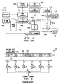
- FIG. 7 there is a diagram showing received power P(A)-P(E) at a mobile unit corresponding to exemplary base stations A-E.
- the maximum received power P(B) from base station B is indicated by dashed line 750.
- a power level indicated by dashed line 752 indicates a power level that is ⁇ less than the maximum received power 750, where ⁇ is the power advantage afforded by STTD over non-diversity transmission.
- the particular value of ⁇ depends on the Doppler rate as previously discussed and typically has a value from 0.7 dB to 3 dB.
- the mobile unit can determine this Doppler rate from the phase shift of received pilot symbols and thereby determine a proper value for ⁇ from a lookup table, equation or other appropriate method.
- a circuit and method for estimating the Doppler frequency is described in detail in copending U.S. Patent application serial number 09/224,632, filed December 31,1998, and incorporated herein by reference.
- This value of ⁇ is then used by the mobile to select a subset of base stations from the candidate list of base stations prior to final selection.
- the subset of base stations includes all base stations having received power bounded by dashed lines 750 and 752.
- the mobile unit will only consider base stations B-D for final selection and exclude base stations A and E.
- the mobile unit determines which of base stations employ STTD diversity as will be explained in detail.
- a base station is selected according to the criteria of TABLE II.
- Base Station B Base Station D Selection Criteria Select No Diversity No Diversity P(B) > P(D) B P(D) > P(B) D Diversity Diversity P(B) > P(D) B P(D) > P(B) D No Diversity Diversity P(B) > P(D) + ⁇ B P(D) > P(D) - ⁇ D Diversity No Diversity P(B) > P(D) - ⁇ B P(D) > P(B) + ⁇ D
- FIG. 8 there is a diagram showing the format of an exemplary time slot transmitted by a base station.
- the time slot includes pilot symbols 740, data symbols 746 and primary (PSC) and secondary (SSC) synchronization channel symbols.
- the pilot symbols are predetermined symbols that are transmitted with each time slot and are known to the mobile unit. These pilot symbols are used by the mobile unit to determine a channel estimate and a Doppler rate.
- the data symbols are STTD encoded and preferably quadrature phase shift keyed (QPSK) data.
- the PSC and SSC symbols are transmitted simultaneously without a long code to facilitate efficient identification of the base station.
- a non-diversity base station transmits +1 PSC or SSC symbols.
- a diversity or STTD base station transmits -1 PSC or SSC symbols. This sign change of the PSC and SSC symbols is compatible with the existing three-stage acquisition process.
- the PSC symbol is modulated with a short code of preferably length 256 that is the same for each base station.
- the received power of each PSC symbol is then used to determine the relative power of each base station. Once the PSC symbol is identified, the timing for the SSC symbol is also known, since both are transmitted simultaneously.
- the SSC symbol is modulated with one of 16 possible orthogonal codes, each orthogonal code corresponding to a respective set of 32 long codes.
- the mobile unit searches the 16 orthogonal codes to match the SSC symbol. This match is preferably performed by a match filter as is well known to those of ordinary skill in the art.
- the mobile unit proceeds to the third stage of acquisition. This third stage requires the mobile unit to identify one group of 32 possible long codes tat modulate the data symbols and determine which of 16 time slots in a frame has been matched. The mobile unit, therefore, must search 512 possible combinations in order to match the long code and decode the data symbols.
- Mobile antenna 212 receives multipath signals transmitted by base station antennas at leads 180 and 182 (FIG. 1), respectively.
- ⁇ represents respective phase rotation of the received signal
- C i represents one of 16 codes corresponding to one of 16 time slots within the received frame
- n i represents additive white Gaussian noise (AWGN).
- AWGN additive white Gaussian noise
- Delay profile estimator circuit 720 couples these received multipath signals r i to lead 704 during receive mode operation.
- Delay profile estimator circuit 720 also receives the multipath signals on lead 704.
- Delay profile estimator circuit 720 includes a despreader circuit as in FIG. 6 and a match filter circuit (not shown).
- the delay profile estimator circuit 720 determines which of the received multipath signals should be combined based on the strength of the match filter output
- the delay profile estimator circuit applies a control signal corresponding to the Doppler rate of the received signal to the WMSA channel estimate circuit 732 via lead 728.
- This control signal determines the variable K number of time slots used by the WMSA channel estimate circuit 732 (FIG. 5).
- the WMSA channel estimate circuit produces channel estimate signals ⁇ 1 / j and ⁇ 2 / j at leads 734 and 736, respectively.
- Phase correction circuit 710 receives these channel estimate signals together with the SSC symbols on lead 708 and produces phase-corrected SSC symbols at rake combiner circuit 710 as in equation [16], where the asterisk represents a complex conjugate operation.
- ⁇ * r i ⁇ *( ⁇ i C i + n i ) Equation [16] is further simplified at equation [17].
- the code C i is known from second stage acquisition and readily removed by the mobile unit leaving SSC symbol ⁇ i and a noise term.
- ⁇ * r i
- each SSC symbol has a constant value ⁇ corresponding to either +1 or -1 depending on the respective absence or presence of transmit diversity.
- the rake combiner circuit produces the resulting signal of equation [18] at lead 716. If the accumulated value at lead 716 is greater than zero, the base station does not use transmit diversity. Alternatively, if the base station does use transmit diversity, the value on lead 716 will be less than zero.
- N 64 time slots corresponding to four data frames, therefore, the mobile unit can readily detect the presence or absence of transmit diversity at each candidate base station in 40 milliseconds. Under these conditions, the probability of incorrectly detecting transmit diversity at a base station as a function of the bit energy to noise ratio (Eb/N0) is given at FIG. 10.
- the probability erroneous diversity detection is approximately 10 -3 .
- This method of diversity detection is highly advantageous in providing reliable transmit diversity detection without Viterbi decoding the received signal. Detection time is greatly reduced over that required by L3 message decoding.
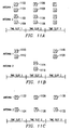
- FIG. 11A through FIG. 11C these PSC and SSC symbols may be transmitted by different diversity formats.
- the embodiment of FIG. 11A of the present invention illustrates simultaneous transmission of the PSC 1102 and SSC 1104 from respective antennas 1 and 2 during time slot 1. This transmission pattern is repeated for PSC 1106 and SSC 1108 from respective antennas 1 and 2 during time slot 2.
- the diagram of FIG. 11B illustrates another embodiment of the present invention, wherein the PSC 1110 and SSC 1112 are transmitted from antenna 1 during time slot 1. The PSC 1114 and SSC 1116 are then transmitted from antenna 2 during time slot 2. The pattern is repeated by transmitting PSC 1118 and SSC 1120 from antenna 1 during time slot 3.
- the diagram of FIG. 11A of the present invention illustrates simultaneous transmission of the PSC 1102 and SSC 1104 from respective antennas 1 and 2 during time slot 1. This transmission pattern is repeated for PSC 1106 and SSC 1108 from respective antennas 1 and 2 during time slot 2.
- the diagram of FIG. 11B illustrates another embodiment of the present invention,
- FIG. 11C illustrates yet another embodiment of the present invention, wherein the PSC 1122 is transmitted from antenna 1 and the SSC 1124 is transmitted from antenna 2 during time slot 1. Next, during next time slot 2, the SSC 1126 is transmitted from antenna 1 and the PSC 1128 is transmitted from antenna 2. This pattern is repeated by transmitting PSC 1130 from antenna 1 and SSC 1132 from antenna 2 during time slot 3.
- Each of these patterns is advantageous in providing transmit diversity for PSC and SSC symbols.
- the other of the PSC and SSC is a known symbol and, therefore, may be used to determine a channel estimate. This channel estimate may be calculated by using the PSC or SSC together with the pilot symbols or in lieu of the pilot symbols.
Landscapes
- Engineering & Computer Science (AREA)
- Computer Networks & Wireless Communication (AREA)
- Signal Processing (AREA)
- Radio Transmission System (AREA)
- Mobile Radio Communication Systems (AREA)
Applications Claiming Priority (4)
| Application Number | Priority Date | Filing Date | Title |
|---|---|---|---|
| US12833899P | 1999-04-08 | 1999-04-08 | |
| US12883799P | 1999-04-09 | 1999-04-09 | |
| US128837P | 1999-04-09 | ||
| US128338 | 1999-04-09 |
Publications (3)
| Publication Number | Publication Date |
|---|---|
| EP1056237A2 true EP1056237A2 (fr) | 2000-11-29 |
| EP1056237A3 EP1056237A3 (fr) | 2006-08-30 |
| EP1056237B1 EP1056237B1 (fr) | 2014-01-22 |
Family
ID=26826497
Family Applications (1)
| Application Number | Title | Priority Date | Filing Date |
|---|---|---|---|
| EP20000107130 Expired - Lifetime EP1056237B1 (fr) | 1999-04-08 | 2000-04-07 | Détection en diversité pour WCDMA |
Country Status (2)
| Country | Link |
|---|---|
| EP (1) | EP1056237B1 (fr) |
| JP (1) | JP4955850B2 (fr) |
Cited By (6)
| Publication number | Priority date | Publication date | Assignee | Title |
|---|---|---|---|---|
| WO2004040799A3 (fr) * | 2002-10-31 | 2004-07-15 | Infineon Technologies Ag | Procede et dispositifs de detection du mode diversite de l'emission pour des recepteurs de telephonie mobile |
| US6775260B1 (en) | 1999-02-25 | 2004-08-10 | Texas Instruments Incorporated | Space time transmit diversity for TDD/WCDMA systems |
| EP1133071A3 (fr) * | 1999-02-25 | 2005-05-18 | Texas Instruments Incorporated | Diversité spatio-temporel pour systèmes à TDD/AMRC |
| WO2007037636A3 (fr) * | 2005-09-28 | 2008-08-07 | Lg Electronics Inc | Procede d'identification d'un signal code spatio-temporel dans un systeme de communication sans fil |
| WO2014189838A1 (fr) * | 2013-05-20 | 2014-11-27 | Qualcomm Incorporated | Estimation de canal à l'aide de signaux pilotes discontinus |
| EP2715959A4 (fr) * | 2011-06-01 | 2015-10-28 | Samsung Electronics Co Ltd | Procédés et appareil permettant de transmettre et de recevoir un signal de synchronisation et des informations de système dans un système de communication sans fil |
Families Citing this family (2)
| Publication number | Priority date | Publication date | Assignee | Title |
|---|---|---|---|---|
| DE60044928D1 (de) | 1999-04-29 | 2010-10-21 | Samsung Electronics Co Ltd | Gerät und verfahren für synkronisation von kanälen in einem breitband w-cdma kommunikationssystem |
| CN101438523A (zh) * | 2006-06-23 | 2009-05-20 | 松下电器产业株式会社 | 无线发送装置、无线接收装置以及导频生成方法 |
Family Cites Families (14)
| Publication number | Priority date | Publication date | Assignee | Title |
|---|---|---|---|---|
| JP3158821B2 (ja) * | 1993-12-14 | 2001-04-23 | 株式会社日立製作所 | Cdma移動通信システムおよび装置 |
| JPH07177072A (ja) * | 1993-12-21 | 1995-07-14 | Nippon Telegr & Teleph Corp <Ntt> | 移動通信用一周波数交互通信方式における時間ダイバーシチ方式 |
| JPH07336346A (ja) * | 1994-06-10 | 1995-12-22 | Sanyo Electric Co Ltd | 制御信号伝送装置およびこれを用いた無線通信システム |
| EP0715440B1 (fr) * | 1994-06-22 | 2004-06-16 | NTT DoCoMo, Inc. | Detecteur synchrone et procede de synchronisation pour un recepteur numerique de telecommunications |
| JP3411150B2 (ja) * | 1996-03-22 | 2003-05-26 | 松下電器産業株式会社 | Cdmaセルラ無線通信装置 |
| US5901185A (en) * | 1996-04-15 | 1999-05-04 | Ericsson Inc. | Systems and methods for data-augmented, pilot-symbol-assisted radiotelephone communications |
| JP3720141B2 (ja) * | 1996-10-01 | 2005-11-24 | 松下電器産業株式会社 | 移動体通信方法およびその装置 |
| JPH10190626A (ja) * | 1996-12-27 | 1998-07-21 | Matsushita Electric Ind Co Ltd | Cdma受信装置 |
| JP3006679B2 (ja) * | 1997-01-16 | 2000-02-07 | 日本電気株式会社 | セルラー移動電話システム |
| JP3349918B2 (ja) * | 1997-04-09 | 2002-11-25 | 沖電気工業株式会社 | 通信システム、送信装置及び受信装置 |
| CA2424556C (fr) * | 1997-04-17 | 2009-11-24 | Ntt Mobile Communications Network Inc. | Station de base de systeme de communications mobiles |
| FR2765063B1 (fr) * | 1997-06-23 | 1999-09-24 | Alsthom Cge Alcatel | Station de base a diversite d'antennes pour l'emission de canaux unidirectionnels, et procede correspondant d'emission d'un canal unidirectionnel par une station de base |
| US6038263A (en) * | 1997-07-31 | 2000-03-14 | Motorola, Inc. | Method and apparatus for transmitting signals in a communication system |
| US6185244B1 (en) * | 1997-08-29 | 2001-02-06 | Telefonaktiebolaget Lm Ericsson | Cell searching in a CDMA communications system |
-
2000
- 2000-04-07 JP JP2000106650A patent/JP4955850B2/ja not_active Expired - Fee Related
- 2000-04-07 EP EP20000107130 patent/EP1056237B1/fr not_active Expired - Lifetime
Cited By (12)
| Publication number | Priority date | Publication date | Assignee | Title |
|---|---|---|---|---|
| US6775260B1 (en) | 1999-02-25 | 2004-08-10 | Texas Instruments Incorporated | Space time transmit diversity for TDD/WCDMA systems |
| EP1133071A3 (fr) * | 1999-02-25 | 2005-05-18 | Texas Instruments Incorporated | Diversité spatio-temporel pour systèmes à TDD/AMRC |
| US7701916B2 (en) | 1999-02-25 | 2010-04-20 | Texas Instruments Incorporated | Space time transmit diversity for TDD with cyclic prefix midamble |
| WO2004040799A3 (fr) * | 2002-10-31 | 2004-07-15 | Infineon Technologies Ag | Procede et dispositifs de detection du mode diversite de l'emission pour des recepteurs de telephonie mobile |
| DE10250861B4 (de) * | 2002-10-31 | 2007-01-04 | Infineon Technologies Ag | Verfahren und Vorrichtungen zur Detektion des TX-Diversity-Modes für Mobilfunkempfänger |
| US7542726B2 (en) | 2002-10-31 | 2009-06-02 | Infineon Technologies Ag | Methods and apparatuses for detecting the TX diversity mode for mobile radio receivers |
| CN1708937B (zh) * | 2002-10-31 | 2012-10-03 | 英特尔移动通信有限责任公司 | 检测移动无线接收器tx分集模式的方法及装置 |
| WO2007037636A3 (fr) * | 2005-09-28 | 2008-08-07 | Lg Electronics Inc | Procede d'identification d'un signal code spatio-temporel dans un systeme de communication sans fil |
| US7826573B2 (en) | 2005-09-28 | 2010-11-02 | Lg Electronics, Inc. | Method of identifying a space-time encoded signal in a wireless communication system |
| US7995512B2 (en) | 2005-09-28 | 2011-08-09 | Lg Electronics Inc. | Method of transmitting data in cellular networks using cooperative relaying |
| EP2715959A4 (fr) * | 2011-06-01 | 2015-10-28 | Samsung Electronics Co Ltd | Procédés et appareil permettant de transmettre et de recevoir un signal de synchronisation et des informations de système dans un système de communication sans fil |
| WO2014189838A1 (fr) * | 2013-05-20 | 2014-11-27 | Qualcomm Incorporated | Estimation de canal à l'aide de signaux pilotes discontinus |
Also Published As
| Publication number | Publication date |
|---|---|
| EP1056237B1 (fr) | 2014-01-22 |
| JP4955850B2 (ja) | 2012-06-20 |
| EP1056237A3 (fr) | 2006-08-30 |
| JP2000324020A (ja) | 2000-11-24 |
Similar Documents
| Publication | Publication Date | Title |
|---|---|---|
| US6804311B1 (en) | Diversity detection for WCDMA | |
| US8059746B2 (en) | Producing STTD diversity signal from rake combined level 3 message | |
| USRE42919E1 (en) | Power control with space time transmit diversity | |
| US8107570B2 (en) | Space time block coded transmit antenna diversity for WCDMA | |
| US6404826B1 (en) | Iterative signal-to-interference ratio estimation for WCDMA | |
| EP1381172A2 (fr) | Procédé et système d'émission en diversité avec antenne adaptative dans un système de communication mobile | |
| US6356605B1 (en) | Frame synchronization in space time block coded transmit antenna diversity for WCDMA | |
| US6424642B1 (en) | Estimation of doppler frequency through autocorrelation of pilot symbols | |
| US6724828B1 (en) | Mobile switching between STTD and non-diversity mode | |
| US6862275B1 (en) | Cell selection with STTD and SSDT | |
| US6166622A (en) | Time slot structure for improved TPC estimation in WCDMA | |
| EP0993129A2 (fr) | Estimation de canal dans une diversité d'émission codée par blocs spatials-temporels pour WCDMA | |
| EP1039658B1 (fr) | Procédé pour faire fonctionner un circuit de communication | |
| EP1056237B1 (fr) | Détection en diversité pour WCDMA | |
| KR20030077888A (ko) | 코드 분할 다중 접속 통신 시스템에서 시공간 송신다이버시티 방식으로 인코딩된 채널 신호 수신 장치 및 방법 | |
| Hyeon Woo et al. | Performance Analysis of Down Link Time Switched Transmit Diversity (TSTD) in W-CDMA system |
Legal Events
| Date | Code | Title | Description |
|---|---|---|---|
| PUAI | Public reference made under article 153(3) epc to a published international application that has entered the european phase |
Free format text: ORIGINAL CODE: 0009012 |
|
| AK | Designated contracting states |
Kind code of ref document: A2 Designated state(s): AT BE CH CY DE DK ES FI FR GB GR IE IT LI LU MC NL PT SE |
|
| AX | Request for extension of the european patent |
Free format text: AL;LT;LV;MK;RO;SI |
|
| PUAL | Search report despatched |
Free format text: ORIGINAL CODE: 0009013 |
|
| AK | Designated contracting states |
Kind code of ref document: A3 Designated state(s): AT BE CH CY DE DK ES FI FR GB GR IE IT LI LU MC NL PT SE |
|
| AX | Request for extension of the european patent |
Extension state: AL LT LV MK RO SI |
|
| RIC1 | Information provided on ipc code assigned before grant |
Ipc: H04L 1/06 20060101AFI20000801BHEP Ipc: H04Q 7/38 20060101ALI20060727BHEP Ipc: H04L 25/02 20060101ALI20060727BHEP |
|
| 17P | Request for examination filed |
Effective date: 20070323 |
|
| AKX | Designation fees paid |
Designated state(s): DE FR GB |
|
| 17Q | First examination report despatched |
Effective date: 20080415 |
|
| GRAJ | Information related to disapproval of communication of intention to grant by the applicant or resumption of examination proceedings by the epo deleted |
Free format text: ORIGINAL CODE: EPIDOSDIGR1 |
|
| GRAP | Despatch of communication of intention to grant a patent |
Free format text: ORIGINAL CODE: EPIDOSNIGR1 |
|
| INTG | Intention to grant announced |
Effective date: 20130723 |
|
| RIC1 | Information provided on ipc code assigned before grant |
Ipc: H04L 25/02 20060101ALI20130712BHEP Ipc: H04L 1/06 20060101AFI20130712BHEP |
|
| RIN1 | Information on inventor provided before grant (corrected) |
Inventor name: DABAK, ANAND G. Inventor name: GATHERER, ALAN Inventor name: KINJO, SHIGENORI Inventor name: HOSUR, SRINATH |
|
| GRAS | Grant fee paid |
Free format text: ORIGINAL CODE: EPIDOSNIGR3 |
|
| GRAA | (expected) grant |
Free format text: ORIGINAL CODE: 0009210 |
|
| AK | Designated contracting states |
Kind code of ref document: B1 Designated state(s): DE FR GB |
|
| REG | Reference to a national code |
Ref country code: GB Ref legal event code: FG4D |
|
| REG | Reference to a national code |
Ref country code: DE Ref legal event code: R096 Ref document number: 60048413 Country of ref document: DE Effective date: 20140306 |
|
| REG | Reference to a national code |
Ref country code: DE Ref legal event code: R097 Ref document number: 60048413 Country of ref document: DE |
|
| PLBE | No opposition filed within time limit |
Free format text: ORIGINAL CODE: 0009261 |
|
| STAA | Information on the status of an ep patent application or granted ep patent |
Free format text: STATUS: NO OPPOSITION FILED WITHIN TIME LIMIT |
|
| 26N | No opposition filed |
Effective date: 20141023 |
|
| REG | Reference to a national code |
Ref country code: DE Ref legal event code: R097 Ref document number: 60048413 Country of ref document: DE Effective date: 20141023 |
|
| REG | Reference to a national code |
Ref country code: FR Ref legal event code: PLFP Year of fee payment: 17 |
|
| REG | Reference to a national code |
Ref country code: FR Ref legal event code: PLFP Year of fee payment: 18 |
|
| REG | Reference to a national code |
Ref country code: FR Ref legal event code: PLFP Year of fee payment: 19 |
|
| PGFP | Annual fee paid to national office [announced via postgrant information from national office to epo] |
Ref country code: GB Payment date: 20190326 Year of fee payment: 20 Ref country code: FR Payment date: 20190320 Year of fee payment: 20 |
|
| PGFP | Annual fee paid to national office [announced via postgrant information from national office to epo] |
Ref country code: DE Payment date: 20190318 Year of fee payment: 20 |
|
| REG | Reference to a national code |
Ref country code: DE Ref legal event code: R071 Ref document number: 60048413 Country of ref document: DE |
|
| REG | Reference to a national code |
Ref country code: GB Ref legal event code: PE20 Expiry date: 20200406 |
|
| PG25 | Lapsed in a contracting state [announced via postgrant information from national office to epo] |
Ref country code: GB Free format text: LAPSE BECAUSE OF EXPIRATION OF PROTECTION Effective date: 20200406 |