EP1056590B1 - Extrudeuse pour petits elements vegetaux - Google Patents
Extrudeuse pour petits elements vegetaux Download PDFInfo
- Publication number
- EP1056590B1 EP1056590B1 EP99903688A EP99903688A EP1056590B1 EP 1056590 B1 EP1056590 B1 EP 1056590B1 EP 99903688 A EP99903688 A EP 99903688A EP 99903688 A EP99903688 A EP 99903688A EP 1056590 B1 EP1056590 B1 EP 1056590B1
- Authority
- EP
- European Patent Office
- Prior art keywords
- filling
- feed shaft
- paddles
- pressing chamber
- agitator
- Prior art date
- Legal status (The legal status is an assumption and is not a legal conclusion. Google has not performed a legal analysis and makes no representation as to the accuracy of the status listed.)
- Expired - Lifetime
Links
- 238000003825 pressing Methods 0.000 claims abstract description 40
- 238000010438 heat treatment Methods 0.000 claims abstract description 28
- 238000000034 method Methods 0.000 claims description 7
- 229910000831 Steel Inorganic materials 0.000 claims description 3
- 239000010959 steel Substances 0.000 claims description 3
- 239000012634 fragment Substances 0.000 claims 4
- 239000002184 metal Substances 0.000 claims 1
- 238000001125 extrusion Methods 0.000 abstract description 30
- 239000000463 material Substances 0.000 abstract description 4
- 235000013311 vegetables Nutrition 0.000 description 10
- 230000008901 benefit Effects 0.000 description 4
- 239000011230 binding agent Substances 0.000 description 2
- 230000006835 compression Effects 0.000 description 2
- 238000007906 compression Methods 0.000 description 2
- 238000005429 filling process Methods 0.000 description 2
- 230000000149 penetrating effect Effects 0.000 description 2
- 230000001133 acceleration Effects 0.000 description 1
- 238000009826 distribution Methods 0.000 description 1
- 230000000694 effects Effects 0.000 description 1
- 239000000203 mixture Substances 0.000 description 1
- 238000005453 pelletization Methods 0.000 description 1
- JTJMJGYZQZDUJJ-UHFFFAOYSA-N phencyclidine Chemical compound C1CCCCN1C1(C=2C=CC=CC=2)CCCCC1 JTJMJGYZQZDUJJ-UHFFFAOYSA-N 0.000 description 1
- 230000001737 promoting effect Effects 0.000 description 1
- 238000003860 storage Methods 0.000 description 1
- 239000005418 vegetable material Substances 0.000 description 1
- 238000010792 warming Methods 0.000 description 1
Images
Classifications
-
- B—PERFORMING OPERATIONS; TRANSPORTING
- B30—PRESSES
- B30B—PRESSES IN GENERAL
- B30B15/00—Details of, or accessories for, presses; Auxiliary measures in connection with pressing
- B30B15/30—Feeding material to presses
- B30B15/302—Feeding material in particulate or plastic state to moulding presses
-
- B—PERFORMING OPERATIONS; TRANSPORTING
- B27—WORKING OR PRESERVING WOOD OR SIMILAR MATERIAL; NAILING OR STAPLING MACHINES IN GENERAL
- B27N—MANUFACTURE BY DRY PROCESSES OF ARTICLES, WITH OR WITHOUT ORGANIC BINDING AGENTS, MADE FROM PARTICLES OR FIBRES CONSISTING OF WOOD OR OTHER LIGNOCELLULOSIC OR LIKE ORGANIC MATERIAL
- B27N3/00—Manufacture of substantially flat articles, e.g. boards, from particles or fibres
- B27N3/08—Moulding or pressing
- B27N3/28—Moulding or pressing characterised by using extrusion presses
-
- B—PERFORMING OPERATIONS; TRANSPORTING
- B29—WORKING OF PLASTICS; WORKING OF SUBSTANCES IN A PLASTIC STATE IN GENERAL
- B29C—SHAPING OR JOINING OF PLASTICS; SHAPING OF MATERIAL IN A PLASTIC STATE, NOT OTHERWISE PROVIDED FOR; AFTER-TREATMENT OF THE SHAPED PRODUCTS, e.g. REPAIRING
- B29C48/00—Extrusion moulding, i.e. expressing the moulding material through a die or nozzle which imparts the desired form; Apparatus therefor
- B29C48/03—Extrusion moulding, i.e. expressing the moulding material through a die or nozzle which imparts the desired form; Apparatus therefor characterised by the shape of the extruded material at extrusion
- B29C48/05—Filamentary, e.g. strands
-
- B—PERFORMING OPERATIONS; TRANSPORTING
- B29—WORKING OF PLASTICS; WORKING OF SUBSTANCES IN A PLASTIC STATE IN GENERAL
- B29C—SHAPING OR JOINING OF PLASTICS; SHAPING OF MATERIAL IN A PLASTIC STATE, NOT OTHERWISE PROVIDED FOR; AFTER-TREATMENT OF THE SHAPED PRODUCTS, e.g. REPAIRING
- B29C48/00—Extrusion moulding, i.e. expressing the moulding material through a die or nozzle which imparts the desired form; Apparatus therefor
- B29C48/03—Extrusion moulding, i.e. expressing the moulding material through a die or nozzle which imparts the desired form; Apparatus therefor characterised by the shape of the extruded material at extrusion
- B29C48/09—Articles with cross-sections having partially or fully enclosed cavities, e.g. pipes or channels
- B29C48/10—Articles with cross-sections having partially or fully enclosed cavities, e.g. pipes or channels flexible, e.g. blown foils
-
- B—PERFORMING OPERATIONS; TRANSPORTING
- B29—WORKING OF PLASTICS; WORKING OF SUBSTANCES IN A PLASTIC STATE IN GENERAL
- B29C—SHAPING OR JOINING OF PLASTICS; SHAPING OF MATERIAL IN A PLASTIC STATE, NOT OTHERWISE PROVIDED FOR; AFTER-TREATMENT OF THE SHAPED PRODUCTS, e.g. REPAIRING
- B29C48/00—Extrusion moulding, i.e. expressing the moulding material through a die or nozzle which imparts the desired form; Apparatus therefor
- B29C48/25—Component parts, details or accessories; Auxiliary operations
- B29C48/36—Means for plasticising or homogenising the moulding material or forcing it through the nozzle or die
- B29C48/475—Means for plasticising or homogenising the moulding material or forcing it through the nozzle or die using pistons, accumulators or press rams
-
- B—PERFORMING OPERATIONS; TRANSPORTING
- B30—PRESSES
- B30B—PRESSES IN GENERAL
- B30B11/00—Presses specially adapted for forming shaped articles from material in particulate or plastic state, e.g. briquetting presses, tabletting presses
- B30B11/22—Extrusion presses; Dies therefor
- B30B11/26—Extrusion presses; Dies therefor using press rams
- B30B11/265—Extrusion presses; Dies therefor using press rams with precompression means
-
- B—PERFORMING OPERATIONS; TRANSPORTING
- B29—WORKING OF PLASTICS; WORKING OF SUBSTANCES IN A PLASTIC STATE IN GENERAL
- B29C—SHAPING OR JOINING OF PLASTICS; SHAPING OF MATERIAL IN A PLASTIC STATE, NOT OTHERWISE PROVIDED FOR; AFTER-TREATMENT OF THE SHAPED PRODUCTS, e.g. REPAIRING
- B29C48/00—Extrusion moulding, i.e. expressing the moulding material through a die or nozzle which imparts the desired form; Apparatus therefor
- B29C48/25—Component parts, details or accessories; Auxiliary operations
- B29C48/285—Feeding the extrusion material to the extruder
- B29C48/288—Feeding the extrusion material to the extruder in solid form, e.g. powder or granules
- B29C48/2886—Feeding the extrusion material to the extruder in solid form, e.g. powder or granules of fillers or of fibrous materials, e.g. short-fibre reinforcements
-
- B—PERFORMING OPERATIONS; TRANSPORTING
- B29—WORKING OF PLASTICS; WORKING OF SUBSTANCES IN A PLASTIC STATE IN GENERAL
- B29K—INDEXING SCHEME ASSOCIATED WITH SUBCLASSES B29B, B29C OR B29D, RELATING TO MOULDING MATERIALS OR TO MATERIALS FOR MOULDS, REINFORCEMENTS, FILLERS OR PREFORMED PARTS, e.g. INSERTS
- B29K2105/00—Condition, form or state of moulded material or of the material to be shaped
- B29K2105/06—Condition, form or state of moulded material or of the material to be shaped containing reinforcements, fillers or inserts
Definitions
- the invention relates to a method for Extruding hollow strands from vegetable, especially small wooden parts with a horizontal acting piston extrusion press, at a feed shaft with its lower end in a filling and pressing room flows and through a reciprocating, one Closing slide with passage opening is closable, the extrusion piston on at least one, the filling and pressing room in Is passed through the extrusion direction penetrating mandrel, as well as on an extrusion press to carry out the Process.
- the invention is therefore based on the object Filling the filling and pressing room with the vegetable Small parts to improve the areas different Avoid density in the strand if possible and performance to increase the extrusion press overall.
- the method according to the invention consists of that the mandrel is designed as a heating tube, and that the vegetable small parts when filling the filling and Press room specifically in the direction of under the heating pipe located area by a in the lower part of the Feed shaft located, from two axes with parallel existing agitator paddles be promoted.
- the invention thus opens up the Possibility of filling the filling and pressing room to accelerate or improve.
- a filling device with an axis is shown in Figure 1 of the DE-GM 89 06 494.1 became known. There it will Small parts batch through an upright feed chute below towards the filling and pressing room of the extrusion press promoted. In the lower part of the feed chute is a Agitator consisting of two around a common axis rotating wings, at least temporarily rotatable driven. This agitator does the job Small parts batch in the filling and in a faster time To promote the extrusion press room than through this free fall of the batch would happen.
- the invention is therefore the additional object based on avoiding these disadvantages and filling a filling and pressing room, which contains a heating tube accelerate without the position of the heating pipe change.
- the device is based on DE-GM 89 06 494.1 to carry out the method according to the invention in that the agitator consists of two with their axes parallel paddles are positioned opposite each other rotatably drivable and staggered are, the direction of conveyance of the paddle on one Of the heating pipe penetrating the filling and pressing chamber.
- Embodiments of the invention result from the Claims 3 to 9.
- the offset of the paddles is chosen such that they are in a basic position in opposite directions extend. In this way it becomes even Loading of the filling and pressing room reached.
- the feed shaft in the The area surrounding the agitator has a hollow cylindrical shape is. Then the agitator works with greater efficiency like a wing compressor.
- the paddles can be made of rubber consist or of a hard material, e.g. Steel, be made, in the latter case recommends attaching the paddles resiliently.
- Another embodiment is claims 7 to 9 in which the feed chute is provided and a holder for the filling opening of the filling and Closing body covering the press room on an upper, extending parallel to the extrusion axis To mount the pivot axis so that it can move in a pendulum-shaped manner such that the filling opening in the end positions of the pendulum movement is either covered by the closing body or congruent to the outlet opening of the feed shaft lies.
- the principle of the swiveling feed chute is out the aforementioned DE-GM 89 06 494.1 known. There is but the pivot bearing for holding the closing body distanced from the swivel axis of the feed shaft.
- the Embodiment of the invention combines the advantages of Agitator according to the invention with a pivotable mounted closing body for covering the Filling opening of the filling and pressing room, this too Combination is particularly suitable for one through a heating mandrel equipped filling and pressing room Filling the extruder faster without closing the heating mandrel strain.
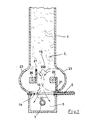
- FIG. 3 shows only that Cross section through a filling and pressing room (5) Extrusion press, as known from DE-A-28 10 070.
- the batch of small parts (3) to be pressed is located in an upright feed chute (2), the lower end of which by a closing slide (6) which can be closed Example of Figure 1 shown in the open position is.
- This closing slide (6) has a passage opening (28), the clear width of which is approximately the cross section of the Filling opening (14) of the filling and pressing room (5) equivalent. If you have the closing slide (6) as with Prior art (DE-A-28 10 070) repeatedly back and forth moved, there is a better distribution of the contents in the filling and pressing room (5).
- the filling and pressing space (5) of the extrusion press becomes centric by extending in the extrusion axis Heating tube (7) penetrates, which has the task of the warming forming strand from the inside and cure. Accordingly, that in Figure 1 is not Extrusion piston shown on this heating tube (7) guided. If the strand to be formed is wider than in figure 1, it may be recommended to use several Arrange the heating pipes (7) next to each other and the Form the extrusion piston accordingly.
- FIG. 1 is also a upright feed shaft (2) in vertical section represented by the vegetable small parts (3) should come down to in the filling and pressing room (5) of the horizontal extrusion press.
- the small vegetable parts can be mixed with binders be, depending on the nature of the to be formed Should own strand.
- an agitator (19) which has the task of vegetable small parts (3) quickly and specifically in the Filling and pressing room (5) to promote without the position of To change the heating pipe.
- the agitator (19) consists of two spaced from each other and stored parallel to each other Shafts (20), each with a single-wing paddle (21) is attached.
- the direction of rotation (22) of the shafts (20) is directed against each other.
- the paddles (21) are in the basic position shown in Figure 1 against each other directed. In this way a flow of conveyed small parts (3) in the direction of the arrows (27) (Conveying direction).
- This conveying direction (27) is deliberately like this chosen that it targets the heating tube (7) and instead whose the lower corner areas of the press and filling room (5) filled in specifically.
- the agitator (19) shown in Figure 1 is in one hollow cylindrical shaft part (23) rotatable stored.
- the single-wing paddle (21) be dimensioned so that they are along the inner surface of the slide along the hollow cylindrical shaft part (23), but this is not absolutely necessary.
- the paddles (21) are made of rubber in one embodiment and therefore have a flexibility that the congestion small parts to be funded can be useful. But it is also conceivable, the paddles (21) made of hard material, e.g. Steel. Then it is recommended that Attach the paddles to the shafts (20) or the Storage of the shafts (20) to make it elastic to achieve certain yield when the small parts jam.
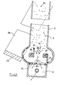
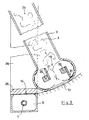
- Figures 2 deals and 3 with a swivel-mounted feed shaft (2) and with a closing slide (25), which together with its holder (26) and the feed shaft (2) from one Open position according to Figure 2 in a closed position can pivot according to Figure 3.
- the bracket (26) and the feed shaft (2) are together by one Swivel axis (24) rotatably mounted.
- the place of The pivot axis (24) is not to scale in the drawing shown.
- the feed chute (2) and the holder (26) has a substantially greater length, whereby the cam track of the closing slide (25) much flatter than shown in the drawing, runs.
- the closing slide (25) must be in the position shown in FIG Position the filling opening (14) of the filling and pressing room (5) Completely complete and on the work stroke to the Take up pressure on the walls of the recipient.
- the slide valve (25) Arrange bracket (26) adjustable in height in order to assemble to maintain the correct closed position and when worn to be able to carry out an adjustment.
- This Adjustment device is not in the drawing shown because they are carried out by usual means can be.
Landscapes
- Engineering & Computer Science (AREA)
- Mechanical Engineering (AREA)
- Life Sciences & Earth Sciences (AREA)
- Manufacturing & Machinery (AREA)
- Wood Science & Technology (AREA)
- Forests & Forestry (AREA)
- Basic Packing Technique (AREA)
- Dry Formation Of Fiberboard And The Like (AREA)
- Processing And Handling Of Plastics And Other Materials For Molding In General (AREA)
- Organic Low-Molecular-Weight Compounds And Preparation Thereof (AREA)
- Formation And Processing Of Food Products (AREA)
- Powder Metallurgy (AREA)
- Solid-Sorbent Or Filter-Aiding Compositions (AREA)
- Extrusion Moulding Of Plastics Or The Like (AREA)
- Fertilizers (AREA)
- Agricultural Chemicals And Associated Chemicals (AREA)
Claims (9)
- Procédé d'extrusion de cordons creux en petites parties (3) végétales, notamment en bois, comprenant une extrudeuse à piston travaillant horizontalement, dans laquelle un puits (2) d'amenée débouche par son extrémité inférieure dans une chambre (5) de remplissage et de pressage et peut être fermé par un tiroir (6) de fermeture allant et venant et ayant une ouverture de passage, le piston de l'extrudeuse étant guidé sur au moins un mandrin (7) traversant la chambre (3) de remplissage et de pressage dans la direction d'extrusion, caractérisé en ce que le mandrin est constitué en tube de chauffage et en ce que les petites parties végétales sont transportées lors du remplissage de la chambre (5) de remplissage et de pressage de manière ciblée en direction de la partie de la chambre de trouvant en-dessous du tube (7) de chauffage par un agitateur (19) se trouvant dans la partie inférieure du puits (2) d'amenée et constitué de deux axes (20) ayant des palettes (21) montées parallèlement l'une à l'autre.
- Dispositif de remplissage pour la chambre (5) de remplissage et de pressage d'une extrudeuse horizontale pour la mise en oeuvre du procédé suivant la revendication 1, constitué d'un puits (2) vertical d'amenée des petites parties (3) végétales à presser, dont l'ouverture (14) de sortie se trouvant en-dessous coïncide avec l'ouverture (14) d'entrée de la chambre (5) de remplissage et de pressage, ouverture qui peut être fermée au moyen d'un tiroir (6) de fermeture, un dispositif (19) d'agitation monté tournant parallèlement à l'axe de l'extrudeuse dans la partie inférieure du puits (2) d'amenée pouvant être, pour accélérer l'opération de remplissage, entraíné au moins de temps en temps, caractérisé en ce que le dispositif (19) d'agitation est constitué de deux pales (21) montées parallèlement entre elles par leur axe (20) et pouvant être entraínées en rotation en sens opposés et étant disposées de manière décalée l'une par rapport à l'autre, la direction de transport des pales (21) passant devant un tube (7) de chauffage qui traverse la chambre (5) de remplissage et de pressage.
- Dispositif de remplissage suivant la revendication 2, caractérisé en ce que le décalage des pales (21) est choisi de façon à ce qu'elles s'étendent en une position de base dans des directions opposées.
- Dispositif de remplissage suivant l'une des revendications 2 ou 3, caractérisé en ce que le puits (2, 23) d'amenée est sous la forme d'un cylindre creux dans la partie entourant le dispositif (19) d'agitation.
- Dispositif de remplissage suivant l'une des revendications 2 ou l'une des suivantes, caractérisé en ce que les pales (21) sont en caoutchouc.
- Dispositif de remplissage suivant l'une des revendications 2 ou l'une des suivantes, caractérisé en ce que les pales (21) sont en un matériau dur, par exemple en acier et, le cas échéant, sont fixées ou montées de manière à céder élastiquement.
- Dispositif de remplissage notamment suivant la revendication 2 ou l'une des suivantes, caractérisé en ce que le puits (19) d'amenée ainsi qu'une fixation (26) pour un tiroir (25) de fermeture recouvrant l'ouverture (14) de remplissage de la chambre (5) de remplissage et de pressage sont montés mobiles en forme de pendule sur un axe (24) supérieur de basculement s'étendant parallèlement à l'axe de l'extrudeuse de façon à ce que, dans les positions d'extrémité du mouvement pendulaire, l'ouverture (14) de remplissage ou bien soit recouverte par le tiroir (25) de fermeture ou bien coïncide avec l'ouverture (14) de sortie du puits (2) d'amenée.
- Dispositif de remplissage suivant la revendication 7, caractérisé en ce que l'axe (24) de basculement est dans le plan vertical passant par l'axe de l'extrudeuse.
- Dispositif de remplissage suivant la revendication 7 ou 8, caractérisé en ce que le tiroir (25) de fermeture est fixé de manière réglable en hauteur à sa fixation (26).
Priority Applications (1)
| Application Number | Priority Date | Filing Date | Title |
|---|---|---|---|
| EP02003527A EP1226928B1 (fr) | 1998-02-04 | 1999-01-28 | Procédé et dispositif d'extrusion de barres creuses à partir de petits éléments végétaux |
Applications Claiming Priority (5)
| Application Number | Priority Date | Filing Date | Title |
|---|---|---|---|
| DE29801829U | 1998-02-04 | ||
| DE29801829U DE29801829U1 (de) | 1998-02-04 | 1998-02-04 | Strangpresse für pflanzliche Kleinteile |
| DE29802527U | 1998-02-14 | ||
| DE29802527U DE29802527U1 (de) | 1998-02-14 | 1998-02-14 | Befüllvorrichtung für den Füll- und Preßraum einer horizontalen Strangpresse |
| PCT/EP1999/000558 WO1999039901A1 (fr) | 1998-02-04 | 1999-01-28 | Extrudeuse pour petits elements vegetaux |
Related Child Applications (1)
| Application Number | Title | Priority Date | Filing Date |
|---|---|---|---|
| EP02003527A Division EP1226928B1 (fr) | 1998-02-04 | 1999-01-28 | Procédé et dispositif d'extrusion de barres creuses à partir de petits éléments végétaux |
Publications (2)
| Publication Number | Publication Date |
|---|---|
| EP1056590A1 EP1056590A1 (fr) | 2000-12-06 |
| EP1056590B1 true EP1056590B1 (fr) | 2003-04-02 |
Family
ID=26061180
Family Applications (1)
| Application Number | Title | Priority Date | Filing Date |
|---|---|---|---|
| EP99903688A Expired - Lifetime EP1056590B1 (fr) | 1998-02-04 | 1999-01-28 | Extrudeuse pour petits elements vegetaux |
Country Status (7)
| Country | Link |
|---|---|
| EP (1) | EP1056590B1 (fr) |
| AT (1) | ATE236010T1 (fr) |
| DE (2) | DE59904847D1 (fr) |
| EE (1) | EE200000436A (fr) |
| LT (1) | LT4826B (fr) |
| PL (1) | PL341870A1 (fr) |
| WO (1) | WO1999039901A1 (fr) |
Family Cites Families (9)
| Publication number | Priority date | Publication date | Assignee | Title |
|---|---|---|---|---|
| GB565031A (en) * | 1943-03-13 | 1944-10-24 | Philplug Products Ltd | Improvements in and relating to apparatus for the manufacture of rods, tubes or plugs |
| US2717420A (en) * | 1951-03-19 | 1955-09-13 | Roy Henri Georges | Artificial lumber products and their manufacture |
| DE2810070C2 (de) | 1978-03-08 | 1982-07-22 | Anton 8891 Unterbernbach Heggenstaller | Schließvorrichtung für Füllstationen von horizontal wirkenden Strangpressen |
| DE3150577C2 (de) * | 1981-12-21 | 1983-12-29 | Anton 8892 Kühbach Heggenstaller | Vorrichtung zum Beschicken des Füllraumes einer horizontalen Kolben-Strangpresse mit einem Gemisch aus pflanzlichen Kleinteilen und Bindemittel zur Herstellung hohlprismatischer Strangpreßprofile |
| FR2527139A1 (fr) * | 1982-05-21 | 1983-11-25 | Freund Pierre | Presse a briquettes, en particulier pour le compactage de dechets combustibles |
| AU5456686A (en) * | 1985-02-28 | 1986-09-24 | Lyon, J.T.W. | A straw compression apparatus |
| JPS6279765A (ja) * | 1985-10-02 | 1987-04-13 | Rheon Autom Mach Co Ltd | 食品材料の計量押し出し装置 |
| DE8906494U1 (de) * | 1989-05-26 | 1990-03-22 | Anton Heggenstaller GmbH, 8892 Kühbach | Strangpresse für pflanzliche Kleinteile |
| DE29802527U1 (de) * | 1998-02-14 | 1998-11-12 | Anton Heggenstaller AG, 86556 Kühbach | Befüllvorrichtung für den Füll- und Preßraum einer horizontalen Strangpresse |
-
1999
- 1999-01-28 PL PL99341870A patent/PL341870A1/xx unknown
- 1999-01-28 EE EEP200000436A patent/EE200000436A/xx unknown
- 1999-01-28 DE DE59904847T patent/DE59904847D1/de not_active Expired - Lifetime
- 1999-01-28 DE DE29903459U patent/DE29903459U1/de not_active Expired - Lifetime
- 1999-01-28 EP EP99903688A patent/EP1056590B1/fr not_active Expired - Lifetime
- 1999-01-28 AT AT99903688T patent/ATE236010T1/de active
- 1999-01-28 WO PCT/EP1999/000558 patent/WO1999039901A1/fr not_active Ceased
-
2000
- 2000-07-19 LT LT2000073A patent/LT4826B/lt not_active IP Right Cessation
Also Published As
| Publication number | Publication date |
|---|---|
| EP1056590A1 (fr) | 2000-12-06 |
| DE29903459U1 (de) | 1999-07-29 |
| LT4826B (lt) | 2001-07-25 |
| PL341870A1 (en) | 2001-05-07 |
| LT2000073A (en) | 2001-03-26 |
| DE59904847D1 (de) | 2003-05-08 |
| ATE236010T1 (de) | 2003-04-15 |
| WO1999039901A1 (fr) | 1999-08-12 |
| EE200000436A (et) | 2001-12-17 |
Similar Documents
| Publication | Publication Date | Title |
|---|---|---|
| DE1604331C2 (de) | Vorrichtung zum Zuteilen und kontrollierten Absetzen genau dosierter Mengen eines plastifizierten Kunststoffes | |
| EP1931951A1 (fr) | Dispositif de dosage pour substances pulverulentes ou pateuses | |
| DE2122858B2 (de) | Einrichtung zum pneumatischen bilden und foerdern von durch druckluftpolster voneinander getrennten materialpfropfen in einer leitung | |
| DE1802643A1 (de) | Verfahren zum Abschneiden von Stangenmaterial | |
| DE2105163A1 (de) | Maschine zum Pressen und Umschnüren von Ballen mit Draht | |
| EP1056590B1 (fr) | Extrudeuse pour petits elements vegetaux | |
| DE9101212U1 (de) | Vorrichtung zur zubereitung von futtermitteln, insbesondere fuer zootiere | |
| DE823063C (de) | Strohzerkleinerungs- und Reibevorrichtung | |
| DD260872A5 (de) | Einrichtung zur zerkleinerung organischer materialien | |
| DE1507959C3 (de) | Maschine zur Erzeugung von Form lingen aus plastischer Masse | |
| CH636950A5 (de) | Vorrichtung zum herstellen von eisstuecken. | |
| EP1226928A2 (fr) | Procédé et dispositif d'extrusion de barres creuses à partir de petits éléments végétaux | |
| DE202010009323U1 (de) | Mischanlage zur Bereitung eines gering viskosen Gemischs | |
| DE2225939C3 (de) | Verfahren und Vorrichtung zur mechanischen Herstellung von sogenannten Handformsteinen | |
| DE69014382T2 (de) | Vorrichtung zum Verdichten und Schneiden von Abfällen, insbesondere Schrott. | |
| DE29802527U1 (de) | Befüllvorrichtung für den Füll- und Preßraum einer horizontalen Strangpresse | |
| DE1529922A1 (de) | Spritzgussmaschinen- bzw. Zylinderkopf mit einem Mundstueck zum Anschluss an Spritzgussformen | |
| WO1994014596A1 (fr) | Extrudeuse a piston | |
| DE2138113A1 (de) | Einrichtung zur verarbeitung moertelaehnlicher massen | |
| DE2052858A1 (de) | Verfahren und Vorrichtung zum Querkeilwalzen | |
| DE635507C (de) | Verfahren und Vorrichtung zur Herstellung von Glashohlkoerpern | |
| DE1129104B (de) | Zufuehrgleitbahn fuer gleichgerichtet liegend abzugebende Tablettenkerne | |
| DE688691C (de) | nderliegenden Arbeitsflaechen bestehende Formsandaufbereitungsanlage | |
| DE1454741A1 (de) | Kalander fuer Bremsbelaege u.dgl. | |
| DE2341388A1 (de) | Verteiler- und verdichterkoerper an einer maschine zur herstellung von formsteinen |
Legal Events
| Date | Code | Title | Description |
|---|---|---|---|
| PUAI | Public reference made under article 153(3) epc to a published international application that has entered the european phase |
Free format text: ORIGINAL CODE: 0009012 |
|
| 17P | Request for examination filed |
Effective date: 20000414 |
|
| AK | Designated contracting states |
Kind code of ref document: A1 Designated state(s): AT BE CH DE DK ES FI FR GB IE IT LI LU NL PT SE |
|
| 17Q | First examination report despatched |
Effective date: 20010814 |
|
| GRAG | Despatch of communication of intention to grant |
Free format text: ORIGINAL CODE: EPIDOS AGRA |
|
| RIN1 | Information on inventor provided before grant (corrected) |
Inventor name: SPIES, XAVER |
|
| GRAG | Despatch of communication of intention to grant |
Free format text: ORIGINAL CODE: EPIDOS AGRA |
|
| GRAH | Despatch of communication of intention to grant a patent |
Free format text: ORIGINAL CODE: EPIDOS IGRA |
|
| GRAH | Despatch of communication of intention to grant a patent |
Free format text: ORIGINAL CODE: EPIDOS IGRA |
|
| GRAA | (expected) grant |
Free format text: ORIGINAL CODE: 0009210 |
|
| AK | Designated contracting states |
Designated state(s): AT BE CH DE DK ES FI FR GB IE IT LI LU NL PT SE |
|
| PG25 | Lapsed in a contracting state [announced via postgrant information from national office to epo] |
Ref country code: NL Free format text: LAPSE BECAUSE OF FAILURE TO SUBMIT A TRANSLATION OF THE DESCRIPTION OR TO PAY THE FEE WITHIN THE PRESCRIBED TIME-LIMIT Effective date: 20030402 Ref country code: IT Free format text: LAPSE BECAUSE OF FAILURE TO SUBMIT A TRANSLATION OF THE DESCRIPTION OR TO PAY THE FEE WITHIN THE PRESCRIBED TIME-LIMIT;WARNING: LAPSES OF ITALIAN PATENTS WITH EFFECTIVE DATE BEFORE 2007 MAY HAVE OCCURRED AT ANY TIME BEFORE 2007. THE CORRECT EFFECTIVE DATE MAY BE DIFFERENT FROM THE ONE RECORDED. Effective date: 20030402 Ref country code: IE Free format text: LAPSE BECAUSE OF NON-PAYMENT OF DUE FEES Effective date: 20030402 Ref country code: GB Free format text: LAPSE BECAUSE OF FAILURE TO SUBMIT A TRANSLATION OF THE DESCRIPTION OR TO PAY THE FEE WITHIN THE PRESCRIBED TIME-LIMIT Effective date: 20030402 Ref country code: FR Free format text: LAPSE BECAUSE OF FAILURE TO SUBMIT A TRANSLATION OF THE DESCRIPTION OR TO PAY THE FEE WITHIN THE PRESCRIBED TIME-LIMIT Effective date: 20030402 Ref country code: FI Free format text: LAPSE BECAUSE OF FAILURE TO SUBMIT A TRANSLATION OF THE DESCRIPTION OR TO PAY THE FEE WITHIN THE PRESCRIBED TIME-LIMIT Effective date: 20030402 |
|
| REG | Reference to a national code |
Ref country code: GB Ref legal event code: FG4D Free format text: NOT ENGLISH |
|
| REG | Reference to a national code |
Ref country code: CH Ref legal event code: EP |
|
| REG | Reference to a national code |
Ref country code: IE Ref legal event code: FG4D Free format text: GERMAN |
|
| REF | Corresponds to: |
Ref document number: 59904847 Country of ref document: DE Date of ref document: 20030508 Kind code of ref document: P |
|
| PG25 | Lapsed in a contracting state [announced via postgrant information from national office to epo] |
Ref country code: SE Free format text: LAPSE BECAUSE OF FAILURE TO SUBMIT A TRANSLATION OF THE DESCRIPTION OR TO PAY THE FEE WITHIN THE PRESCRIBED TIME-LIMIT Effective date: 20030702 Ref country code: PT Free format text: LAPSE BECAUSE OF FAILURE TO SUBMIT A TRANSLATION OF THE DESCRIPTION OR TO PAY THE FEE WITHIN THE PRESCRIBED TIME-LIMIT Effective date: 20030702 Ref country code: DK Free format text: LAPSE BECAUSE OF FAILURE TO SUBMIT A TRANSLATION OF THE DESCRIPTION OR TO PAY THE FEE WITHIN THE PRESCRIBED TIME-LIMIT Effective date: 20030702 |
|
| NLV1 | Nl: lapsed or annulled due to failure to fulfill the requirements of art. 29p and 29m of the patents act | ||
| GBV | Gb: ep patent (uk) treated as always having been void in accordance with gb section 77(7)/1977 [no translation filed] |
Effective date: 20030402 |
|
| PG25 | Lapsed in a contracting state [announced via postgrant information from national office to epo] |
Ref country code: ES Free format text: LAPSE BECAUSE OF FAILURE TO SUBMIT A TRANSLATION OF THE DESCRIPTION OR TO PAY THE FEE WITHIN THE PRESCRIBED TIME-LIMIT Effective date: 20031030 |
|
| REG | Reference to a national code |
Ref country code: IE Ref legal event code: FD4D Ref document number: 1056590E Country of ref document: IE |
|
| PG25 | Lapsed in a contracting state [announced via postgrant information from national office to epo] |
Ref country code: LU Free format text: LAPSE BECAUSE OF NON-PAYMENT OF DUE FEES Effective date: 20040128 |
|
| PG25 | Lapsed in a contracting state [announced via postgrant information from national office to epo] |
Ref country code: LI Free format text: LAPSE BECAUSE OF NON-PAYMENT OF DUE FEES Effective date: 20040131 Ref country code: CH Free format text: LAPSE BECAUSE OF NON-PAYMENT OF DUE FEES Effective date: 20040131 Ref country code: BE Free format text: LAPSE BECAUSE OF NON-PAYMENT OF DUE FEES Effective date: 20040131 |
|
| PLBE | No opposition filed within time limit |
Free format text: ORIGINAL CODE: 0009261 |
|
| STAA | Information on the status of an ep patent application or granted ep patent |
Free format text: STATUS: NO OPPOSITION FILED WITHIN TIME LIMIT |
|
| EN | Fr: translation not filed | ||
| 26N | No opposition filed |
Effective date: 20040105 |
|
| BERE | Be: lapsed |
Owner name: ANTON *HEGGENSTALLER A.G. Effective date: 20040131 |
|
| REG | Reference to a national code |
Ref country code: CH Ref legal event code: PL |
|
| REG | Reference to a national code |
Ref country code: DE Ref legal event code: R082 Ref document number: 59904847 Country of ref document: DE Representative=s name: ERNICKE UND KOLLEGEN, DE |
|
| REG | Reference to a national code |
Ref country code: DE Ref legal event code: R082 Ref document number: 59904847 Country of ref document: DE Representative=s name: ERNICKE PATENT- UND RECHTSANWAELTE, DE Effective date: 20140729 Ref country code: DE Ref legal event code: R082 Ref document number: 59904847 Country of ref document: DE Representative=s name: PATENTANWAELTE ERNICKE UND KOLLEGEN, DE Effective date: 20140729 Ref country code: DE Ref legal event code: R082 Ref document number: 59904847 Country of ref document: DE Representative=s name: ERNICKE UND KOLLEGEN, DE Effective date: 20140729 Ref country code: DE Ref legal event code: R081 Ref document number: 59904847 Country of ref document: DE Owner name: FIRMA PFEIFER HOLZ GMBH, DE Free format text: FORMER OWNER: ANTON HEGGENSTALLER AG, 86556 KUEHBACH, DE Effective date: 20140729 |
|
| REG | Reference to a national code |
Ref country code: DE Ref legal event code: R082 Ref document number: 59904847 Country of ref document: DE Representative=s name: ERNICKE PATENT- UND RECHTSANWAELTE, DE |
|
| PGFP | Annual fee paid to national office [announced via postgrant information from national office to epo] |
Ref country code: DE Payment date: 20180224 Year of fee payment: 20 |
|
| PGFP | Annual fee paid to national office [announced via postgrant information from national office to epo] |
Ref country code: AT Payment date: 20180220 Year of fee payment: 20 |
|
| REG | Reference to a national code |
Ref country code: DE Ref legal event code: R071 Ref document number: 59904847 Country of ref document: DE |
|
| REG | Reference to a national code |
Ref country code: AT Ref legal event code: MK07 Ref document number: 236010 Country of ref document: AT Kind code of ref document: T Effective date: 20190128 |