EP1056628B1 - Vorrichtung zum gelenkigen verbinden eines wischblatts für scheiben von kraftfahrzeugen mit einem wischerarm und verfahren zum herstellen dieser verbindung - Google Patents
Vorrichtung zum gelenkigen verbinden eines wischblatts für scheiben von kraftfahrzeugen mit einem wischerarm und verfahren zum herstellen dieser verbindung Download PDFInfo
- Publication number
- EP1056628B1 EP1056628B1 EP99955700A EP99955700A EP1056628B1 EP 1056628 B1 EP1056628 B1 EP 1056628B1 EP 99955700 A EP99955700 A EP 99955700A EP 99955700 A EP99955700 A EP 99955700A EP 1056628 B1 EP1056628 B1 EP 1056628B1
- Authority
- EP
- European Patent Office
- Prior art keywords
- wiper
- wiper arm
- spring
- longitudinal
- securing
- Prior art date
- Legal status (The legal status is an assumption and is not a legal conclusion. Google has not performed a legal analysis and makes no representation as to the accuracy of the status listed.)
- Expired - Lifetime
Links
- 238000004519 manufacturing process Methods 0.000 title description 3
- 238000000034 method Methods 0.000 claims description 7
- 210000002105 tongue Anatomy 0.000 description 11
- 230000008878 coupling Effects 0.000 description 4
- 238000010168 coupling process Methods 0.000 description 4
- 238000005859 coupling reaction Methods 0.000 description 4
- 230000015572 biosynthetic process Effects 0.000 description 2
- 238000011161 development Methods 0.000 description 2
- 230000018109 developmental process Effects 0.000 description 2
- 230000006870 function Effects 0.000 description 2
- 238000009434 installation Methods 0.000 description 2
- 230000008569 process Effects 0.000 description 2
- 230000009471 action Effects 0.000 description 1
- 230000036461 convulsion Effects 0.000 description 1
- 239000007822 coupling agent Substances 0.000 description 1
- 230000006735 deficit Effects 0.000 description 1
- 230000008407 joint function Effects 0.000 description 1
Images


Classifications
-
- B—PERFORMING OPERATIONS; TRANSPORTING
- B60—VEHICLES IN GENERAL
- B60S—SERVICING, CLEANING, REPAIRING, SUPPORTING, LIFTING, OR MANOEUVRING OF VEHICLES, NOT OTHERWISE PROVIDED FOR
- B60S1/00—Cleaning of vehicles
- B60S1/02—Cleaning windscreens, windows or optical devices
- B60S1/04—Wipers or the like, e.g. scrapers
- B60S1/32—Wipers or the like, e.g. scrapers characterised by constructional features of wiper blade arms or blades
- B60S1/38—Wiper blades
-
- B—PERFORMING OPERATIONS; TRANSPORTING
- B60—VEHICLES IN GENERAL
- B60S—SERVICING, CLEANING, REPAIRING, SUPPORTING, LIFTING, OR MANOEUVRING OF VEHICLES, NOT OTHERWISE PROVIDED FOR
- B60S1/00—Cleaning of vehicles
- B60S1/02—Cleaning windscreens, windows or optical devices
- B60S1/04—Wipers or the like, e.g. scrapers
- B60S1/32—Wipers or the like, e.g. scrapers characterised by constructional features of wiper blade arms or blades
- B60S1/40—Connections between blades and arms
- B60S1/4038—Connections between blades and arms for arms provided with a channel-shaped end
- B60S1/4064—Connections between blades and arms for arms provided with a channel-shaped end the channel-shaped end being provided with protrusions on, or holes in, the side walls to create a pivot
-
- B—PERFORMING OPERATIONS; TRANSPORTING
- B60—VEHICLES IN GENERAL
- B60S—SERVICING, CLEANING, REPAIRING, SUPPORTING, LIFTING, OR MANOEUVRING OF VEHICLES, NOT OTHERWISE PROVIDED FOR
- B60S1/00—Cleaning of vehicles
- B60S1/02—Cleaning windscreens, windows or optical devices
- B60S1/04—Wipers or the like, e.g. scrapers
- B60S1/32—Wipers or the like, e.g. scrapers characterised by constructional features of wiper blade arms or blades
- B60S1/38—Wiper blades
- B60S1/3848—Flat-type wiper blade, i.e. without harness
- B60S1/3849—Connectors therefor; Connection to wiper arm; Attached to blade
- B60S1/3851—Mounting of connector to blade assembly
- B60S1/3858—Mounting of connector to blade assembly with protrusions cooperating with holes
-
- B—PERFORMING OPERATIONS; TRANSPORTING
- B60—VEHICLES IN GENERAL
- B60S—SERVICING, CLEANING, REPAIRING, SUPPORTING, LIFTING, OR MANOEUVRING OF VEHICLES, NOT OTHERWISE PROVIDED FOR
- B60S1/00—Cleaning of vehicles
- B60S1/02—Cleaning windscreens, windows or optical devices
- B60S1/04—Wipers or the like, e.g. scrapers
- B60S1/32—Wipers or the like, e.g. scrapers characterised by constructional features of wiper blade arms or blades
- B60S1/40—Connections between blades and arms
-
- B—PERFORMING OPERATIONS; TRANSPORTING
- B60—VEHICLES IN GENERAL
- B60S—SERVICING, CLEANING, REPAIRING, SUPPORTING, LIFTING, OR MANOEUVRING OF VEHICLES, NOT OTHERWISE PROVIDED FOR
- B60S1/00—Cleaning of vehicles
- B60S1/02—Cleaning windscreens, windows or optical devices
- B60S1/04—Wipers or the like, e.g. scrapers
- B60S1/32—Wipers or the like, e.g. scrapers characterised by constructional features of wiper blade arms or blades
- B60S1/38—Wiper blades
- B60S1/3848—Flat-type wiper blade, i.e. without harness
- B60S1/3849—Connectors therefor; Connection to wiper arm; Attached to blade
- B60S1/3851—Mounting of connector to blade assembly
- B60S1/3853—Snap-fit, e.g. elastic connection
-
- B—PERFORMING OPERATIONS; TRANSPORTING
- B60—VEHICLES IN GENERAL
- B60S—SERVICING, CLEANING, REPAIRING, SUPPORTING, LIFTING, OR MANOEUVRING OF VEHICLES, NOT OTHERWISE PROVIDED FOR
- B60S1/00—Cleaning of vehicles
- B60S1/02—Cleaning windscreens, windows or optical devices
- B60S1/04—Wipers or the like, e.g. scrapers
- B60S1/32—Wipers or the like, e.g. scrapers characterised by constructional features of wiper blade arms or blades
- B60S1/38—Wiper blades
- B60S1/3848—Flat-type wiper blade, i.e. without harness
- B60S1/3849—Connectors therefor; Connection to wiper arm; Attached to blade
- B60S1/3863—Connectors having a spoiler
-
- B—PERFORMING OPERATIONS; TRANSPORTING
- B60—VEHICLES IN GENERAL
- B60S—SERVICING, CLEANING, REPAIRING, SUPPORTING, LIFTING, OR MANOEUVRING OF VEHICLES, NOT OTHERWISE PROVIDED FOR
- B60S1/00—Cleaning of vehicles
- B60S1/02—Cleaning windscreens, windows or optical devices
- B60S1/04—Wipers or the like, e.g. scrapers
- B60S1/32—Wipers or the like, e.g. scrapers characterised by constructional features of wiper blade arms or blades
- B60S1/38—Wiper blades
- B60S2001/3812—Means of supporting or holding the squeegee or blade rubber
- B60S2001/3817—Means of supporting or holding the squeegee or blade rubber chacterised by a backing strip to aid mounting of squeegee in support
- B60S2001/382—Means of supporting or holding the squeegee or blade rubber chacterised by a backing strip to aid mounting of squeegee in support the backing strip being an essentially planar reinforcing strip, e.g. vertebra
-
- B—PERFORMING OPERATIONS; TRANSPORTING
- B60—VEHICLES IN GENERAL
- B60S—SERVICING, CLEANING, REPAIRING, SUPPORTING, LIFTING, OR MANOEUVRING OF VEHICLES, NOT OTHERWISE PROVIDED FOR
- B60S1/00—Cleaning of vehicles
- B60S1/02—Cleaning windscreens, windows or optical devices
- B60S1/04—Wipers or the like, e.g. scrapers
- B60S1/32—Wipers or the like, e.g. scrapers characterised by constructional features of wiper blade arms or blades
- B60S1/38—Wiper blades
- B60S2001/3812—Means of supporting or holding the squeegee or blade rubber
- B60S2001/3825—Means of supporting or holding the squeegee or blade rubber the squeegee mounted directly to or in wiper blade arm
Definitions
- the invention relates to a connecting device according to the Genus of claim 1.
- one of the prior art belonging device of this type (DE 198 38 88 3.7, still not published) belong to this two together connectable coupling halves, one of which is fixed with the wiper arm and the other fixed to the support element of the Wischblatts are connected.
- the one with a comparatively large production costs produced coupling halves are lost if the fixed to the support element Wiper strip and / or the wiper arm, for example because Wear, need to be replaced.
- Bei.der inventive connecting device with the Characteristic features of claim 1 are the Wischerarm Schotter arm by in the already existing cheeks of the wiper arm arranged Bearing holes formed. A specially trained Coupling element can be omitted.
- the connection between Wiper arm and wiper blade is made of loose, reusable Assured fuse elements, which on the one hand the Edge strip of the likewise existing support element belonging, reusable longitudinal rails and grasp others with their pivot pins in the bearing bores of the Wiper arm are stored.
- a particularly easy to handle joint connection arises when each of the two security elements one has substantially C-shaped cross section, the C-leg the edge strips of the longitudinal spring rails of the support element include and the pivot pins on the outsides of the each C-base are arranged, because so each Securing element with its pivot pin in this assigned bearing bore can be used and after the edge strips in the receiving longitudinal grooves of the Wischance sitting longitudinal spring rails of the support element in the of the cross-sectional shape of the fuse elements enclosed receiving space can be inserted.
- the connecting device according to claim 4 allows a particularly advantageous method for producing this Articulated connection in which, in a first step, the Securing elements with their pivot pins from each other facing cheeks of the wiper arm in her Bearing holes are used and then with the Wiper strip provided support element with the edge strips its longitudinal rails between the C-legs of the Secured elements is introduced, with securing means for fixing the support element to the securing elements be effective.
- the inventive method is characterized through a series of simple, straightforward Assembly movements so that it is special machine friendly.
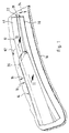
- FIG. 1 shows a perspective view Representation of the middle section of a disk applied, hinged to a wiper arm Wischblatts
- Figure 2 is a partial section through the wiper arm and the wiper blade according to Figure 1 along the line II-II and a side view of the provided with security elements Wischblatts
- Figure 3 the sectional area of a section along the line III-III through the arrangement of Figure 2
- Figure 4 shows the sectional area of a section through the arrangement according to Figure 2 along the line IV-IV
- Figure 5 a Section along the line V-V by the arrangement according to Figure 2
- Figure 6 shows the joint between Wiper arm and wiper blade required components before the Assembly
- Figure 8 is a rotated drawn partial view of a fuse element in the direction of the arrow VIII in Figure 6 and Figure 9 another Embodiment of the fuse element according to FIG. 8
- FIG. 1 A perspective view in Fig. 1 center section a created on a disc 10 of a motor vehicle Wiper blade 12 is at the free end of a motor vehicle guided, driven wiper arm 14 hinged.
- the Wiper arm 14 is in the direction of arrow 16 to the disc 10th loaded and places the wiper blade 10 with the wiper lip 18th his elongated, rubber-elastic wiper strip 20 at the surface of the disc 10 to be wiped:
- the Wiper strip 20 is elongated from a band-like Support member 22 is held, to the embodiment two longitudinal rails 38 belong.
- the support element can also be designed as a one-piece band, where the Disk 10 facing lower belt surface the wiper strip is arranged and with edge strips laterally over the Wiper strip 20 protrudes.
- Wiper arm 14 and wiper blade 12 allow a continuous adjustment of the wiper lip 18 to the in all Generally spherical disc 10 when the wiper blade his working movement (double arrow 24) between reversal positions performs.
- the wiper blade swings around a joint axis 26, which is shown in phantom in FIG.
- the design of the wiper blade 12 in particular show the Figures 3, 4 and 6.
- the elongated, rubber-elastic wiper strip 20 at a distance from the wiper disk 10 two longitudinal grooves 36 has, to the opposite longitudinal sides of the Wiper strip 20 are open towards the edge.
- the longitudinal grooves 36 are in a common plane and serve to accommodate each a longitudinal rail 38 whose length is about the length of Wiper strip 20 corresponds.
- the two longitudinal rails 38 belong to a band-like elongated, elastic Support member 40, which is the rubber-elastic wiper strip 20 stabilized.
- the wiper strip 20 extends with a Web bar 42 between the two longitudinal rails 38 therethrough on the side facing away from the disc 10 top 44 of the Support element 40.
- Wind deflector 46 indicates over its longitudinal extent, which at least approximately the length of the wiper strip 20 corresponds to a longitudinal groove 48, which during the wiping operation of Directed main flow direction of the wind opposite is and so for an increase of the contact pressure of Wiper lip 18 on the disc 10 provides. This is appropriate because especially at high speeds by the Interact several components of the arrow 16 in Figure 1 indicated contact pressure for the wiper blade is weakened. Further, the figures 4 and 6 removable, that each of the resilient longitudinal rails 38 at least over a longitudinal section with a marginal strip 50 protrudes from its longitudinal receiving groove 36 of the wiper strip 20.
- the wiper blade 12 with the wiper arm 14 articulated can be connected is a in Figure 6 perspective illustrated adapter 52 is provided, the two Safety elements 54 each of which has one of associated with both edge strips 50.
- Each of the two Securing elements 54 has a substantially C-shaped Cross-section. Their arrangement with each other is such that the free ends of the C-legs 56 directed against each other are. It follows that the respective base walls 58 on the opposite sides of the C-leg 56th lie.
- the between the two to a fuse element 54 belonging C-leg 56 remaining, trough-shaped space 60 serves to receive the edge strips 50 of the longitudinal rails 38 and the support member 40 ( Figures 3 and 4). Further, FIG.
- FIGS. 5 to 7 show that at a distance from the joint or trunnions 62 in each C base wall 58 of the two Securing elements 54 one-end with the base wall connected spring tongue 64 is formed, which at her free end is provided with a locking cam 66.
- the Arrangement of the two locking cams 66 on the two spring tongues 64 is made so that they are directed against each other.
- the adapter 52 thus formed is in one piece from a made of elastic plastic.
- a restoring force deflection movement (arrow 78 in Figure 7) of the two spring tongues 64 possible.
- the two belonging to the adapter 52 securing elements 54 are against one of the leaf spring acting as a V-shaped Volume 68 outgoing restoring force zubewegbar each other.
- the process of connecting is as follows explained in particular with reference to FIG. First, the Adapter 52 in the direction of the two arrows 72 as far together pressed that the two pivot pin 62 between the cheeks 32 of the wiper arm 14 can be introduced. This happens against the restoring force of the leaf spring acting V-shaped band 68th The installation of the adapter 52nd on the wiper arm 14 takes place in the direction of arrow 74.
- the adapter 52 exercises next to his Joint function - together with the wiper arm - and the Wiper blade positioning - together with the edge strips 50 or with the existing in this Rastworkn 80 - also another backup function, which is in it it can be seen that when in operation wiper blade this - because of the locking cam 66 and with these cooperating and locking seats 80 caused Lock - can not solve the wiper arm 14. Also secures the adapter 52 with its two fuse elements 54 lying in the channel-shaped spaces 60 spring longitudinal rails 38 of the support member 40 against lateral Moving out of the longitudinal grooves 36 during the Wiper operation.
- the wiper blade together with the Wiper arm in the direction of arrow 84 in Figure 1 of the Disc is folded away, the wiper blade can not unintentionally release from the wiper arm, onto the Vehicle car body fall down and cause damage there.
- the two securing elements 54 causes connecting leaf spring 68 once a simple installation of the Adapters between the cheeks 32 and the other allows the V-shape of the leaf spring 68 crossing the Wind deflector 46. Transverse recesses in the Wind deflector 46, which special steps can thus be omitted.
- the distances are 88 between the two C-legs 56 of the securing elements 54th greater than the thickness 90 of the spring rail edge strips 50th
- a free mobility of the two Longitudinal rails 38 and the support member 40 in Direction of the arrows 86 is according to a first embodiment one inner wall of a C-leg one to the other C-leg rearwardly projecting support cam 92 arranged (FIG 9).
- FIGS. 8 and 9 show that the distances are 88 between the two C-legs 56 of the securing elements 54th greater than the thickness 90 of the spring rail edge strips 50th
Landscapes
- Engineering & Computer Science (AREA)
- Mechanical Engineering (AREA)
- Pivots And Pivotal Connections (AREA)
- Transmission Devices (AREA)
- Body Structure For Vehicles (AREA)
- Automobile Manufacture Line, Endless Track Vehicle, Trailer (AREA)
Description
Claims (10)
- Vorrichtung zum gelenkigen Verbinden eines Wischblatts (12) für Scheiben (10) von Kraftfahrzeugen mit einem an diesem geführten, zwischen Umkehrlagen bewegbaren Wischerarm (14), der zwei in Bewegungsrichtung mit Abstand voneinander, parallel zueinander und zur Scheibe stehend angeordnete Wangen (32) hat, die je von einer eine gemeinsame Längsachse (26) aufweisenden Lagerbohrung (34) durchdrungen sind, mit einer langgestreckten, gummielastischen an der zu wischenden Scheibe (10) mit einer Wischlippe (18) anlegbaren, von einem bandartig langgestreckten, federelastischen Tragelement (40) gehaltenen Wischleiste (20) und mit zwei zur Gelenkverbindung gehörenden, quer zur Längserstreckung des Tragelements ausgerichteten, in jeweils einer der beiden Lagerbohrungen (34) geführten Gelenkzapfen (62), dadurch gekennzeichnet, dass die Wischleiste (20) an ihren Längsseiten je eine Aufnahme-Längsnut (36) für jeweils eine Längsschiene (38) des Tragelements (40) hat aus der jede zumindest über einen Längsabschnitt mit einem Randstreifen (50) ragt, dass jeder Randstreifen (50) von einem Sicherungselement (54) gefasst ist, die an einem am Wischarm (14) vormontierbaren Adapter (52) angeordnet sind, und dass an den voneinander abgewandten Längsseiten eines jedes Sicherungselements (54) jeweils einer der beiden Gelenkzapfen (62) angeordnet ist.
- Vorrichtung nach Anspruch 1 dadurch gekennzeichnet, daß der Wischerarm (14) zumindest über einen Längsabschnitt einen etwa U-förmigen Querschnitt hat und daß die Lagerbohrungen (34) in den die Wangen (32) bildenden U-Schenkeln (30) des Wischerarms (14) angeordnet sind.
- Vorrichtung nach einem der Ansprüche 1 oder 2, dadurch gekennzeichnet, daß jedes der beiden Sicherungselemente (54) einen im wesentlichen C-förmigen Querschnitt hat deren C-Schenkel (56) die Randstreifen (50) der Längs-Federschienen (38) des Tragelements (40) umfassen und daß die Gelenkzapfen (62) an den Außenseiten der jeweiligen C-Basis (58) angeordnet sind.
- Vorrichtung nach Anspruch 3 dadurch gekennzeichnet, daß die Gelenkzapfen (62) jeweils an dem einen Endabschnitt eines Sicherungselements (54) sitzen, daß mit Abstand von diesen in jeder C-Basis (58) der beiden Sicherungselemente (54) eine einendig mit dieser verbundene Federzunge (64) angeordnet ist, die mit einem Rastnocken (66) in den zwischen den C-Schenkeln vorhandenen rinnenartigen Aufnahmeraum (60) für jeweils eine Federschiene (38) ragt und daß jede dieser Federschienen mit einer dem jeweiligen Rastnocken (66) zugeordneten Rastaufnahme (80) versehen ist.
- Vorrichtung nach einem der Ansprüche 1 bis 4 dadurch gekennzeichnet, daß die beiden Sicherungselemente (54) durch Federmittel (68) miteinander verbunden sind.
- Vorrichtung nach Anspruch 5, dadurch gekennzeichnet, daß die Federmittel durch ein die Wischleiste (20) querendes, im wesentlichen V-förmiges Band (68) gebildet sind, dessen freie Enden der V-Schenkel (70) mit je einem der beiden Sicherungselemente (54) verbunden sind.
- Vorrichtung nach Anspruch 6, dadurch gekennzeichnet, daß sowohl die beiden Sicherungselemente (54) als auch das Federband (68) aus einem elastischen Kunststoff hergestellt und einstückig miteinander verbunden sind.
- Vorrichtung nach einem der Ansprüche 4 bis 7, dadurch gekennzeichnet, daß der Wischerarm (14) die C-Basis (58) der beiden Sicherungselemente (54) an deren voneinander abgewandten Außenseiten mit seinen Wangen (32) passend übergreift.
- Vorrichtung nach einem der Ansprüche 3 bis 8, dadurch gekennzeichnet, daß die Abstände (88) zwischen den beiden C-Schenkeln (56) eines jeden Sicherungselements (54) größer ist als die Dicke (90) der Federschienen-Randstreifen (50) und daß an der einen Innenwand des einen C-Schenkels eines jeden Sicherungselements wenigstens ein zum anderen C-Schenkel hinvorspringender Stütznocken (92) angeordnet ist.
- Verfahren zum gelenkigen Verbinden eines Wischblatts mit einem Wischerarm mittels einer Vorrichtung gemäß einem der Ansprüche 4 bis 9, bei dem in einem ersten Verfahrensschritt die Sicherungselemente (54) mit ihren Gelenkzapfen (62) von den einander zugewandten Wangen (32) des Wischerarms (14) aus in ihre Lagerbohrungen (34) eingesetzt werden und danach das mit der Wischleiste (20) versehene Tragelement (40) mit den Randstreifen (50) seiner Längsschienen (38) zwischen die C-Schenkel (56) der Sicherungselemente (54) eingebracht wird wobei Sicherungsmittel (66, 80) zum Fixieren des Tragelements an den Sicherungselementen wirksam werden.
Applications Claiming Priority (3)
| Application Number | Priority Date | Filing Date | Title |
|---|---|---|---|
| DE19860644 | 1998-12-28 | ||
| DE19860644A DE19860644A1 (de) | 1998-12-29 | 1998-12-29 | Vorrichtung zum gelenkigen Verbinden eines Wischblatts für Scheiben von Kraftfahrzeugen mit einem Wischerarm und Verfahren zum Herstellen dieser Verbindung |
| PCT/DE1999/002920 WO2000038964A1 (de) | 1998-12-29 | 1999-09-15 | Vorrichtung zum gelenkigen verbinden eines wischblatts für scheiben von kraftfahrzeugen mit einem wischerarm und verfahren zum herstellen dieser verbindung |
Publications (2)
| Publication Number | Publication Date |
|---|---|
| EP1056628A1 EP1056628A1 (de) | 2000-12-06 |
| EP1056628B1 true EP1056628B1 (de) | 2005-09-14 |
Family
ID=7893070
Family Applications (1)
| Application Number | Title | Priority Date | Filing Date |
|---|---|---|---|
| EP99955700A Expired - Lifetime EP1056628B1 (de) | 1998-12-29 | 1999-09-15 | Vorrichtung zum gelenkigen verbinden eines wischblatts für scheiben von kraftfahrzeugen mit einem wischerarm und verfahren zum herstellen dieser verbindung |
Country Status (7)
| Country | Link |
|---|---|
| US (1) | US6634055B1 (de) |
| EP (1) | EP1056628B1 (de) |
| JP (1) | JP4550287B2 (de) |
| KR (1) | KR100605237B1 (de) |
| BR (1) | BR9908330A (de) |
| DE (2) | DE19860644A1 (de) |
| WO (1) | WO2000038964A1 (de) |
Cited By (4)
| Publication number | Priority date | Publication date | Assignee | Title |
|---|---|---|---|---|
| US8806700B2 (en) | 2011-07-29 | 2014-08-19 | Pylon Manufacturing Corporation | Wiper blade connector |
| US9108595B2 (en) | 2011-07-29 | 2015-08-18 | Pylon Manufacturing Corporation | Windshield wiper connector |
| US9457768B2 (en) | 2011-04-21 | 2016-10-04 | Pylon Manufacturing Corp. | Vortex damping wiper blade |
| USD777079S1 (en) | 2014-10-03 | 2017-01-24 | Pylon Manufacturing Corp. | Wiper blade frame |
Families Citing this family (49)
| Publication number | Priority date | Publication date | Assignee | Title |
|---|---|---|---|---|
| DE10036122B4 (de) * | 2000-07-25 | 2010-12-16 | Volkswagen Ag | Wischerblatt zur Anordnung am Wischerarm einer Scheibenwischeranlage |
| DE10194663D2 (de) | 2000-10-28 | 2003-10-02 | Bosch Gmbh Robert | Vorrichtung zum lösbaren, gelenkigen Verbinden eines Wischblatts zum Reinigen von Scheiben mit einem Wischerarm |
| DE10057253A1 (de) | 2000-11-18 | 2002-05-23 | Bosch Gmbh Robert | Top-Lock-Verbindung Gelenkfreies WBA |
| DE10194924D2 (de) * | 2000-11-18 | 2003-10-09 | Bosch Gmbh Robert | Vorrichtung zum Lösbaren Verbinden eines Wischblatts zum Reinigen von Scheiben insbesondere von Kraftfahrzeugen mit einem angetriebenen Wischerarm |
| DE10058208B4 (de) * | 2000-11-23 | 2009-06-04 | Valeo Auto-Electric Wischer Und Motoren Gmbh | Wischvorrichtung |
| DE10065124A1 (de) | 2000-12-28 | 2002-07-04 | Bosch Gmbh Robert | Vorrichtung zum lösbaren Verbinden eines Wischblatts mit einem Wischerarm |
| ES2246286T3 (es) * | 2001-05-08 | 2006-02-16 | Federal-Mogul S.A. | Dispositivo de limpiaparabrisas. |
| WO2003084789A1 (de) * | 2002-04-04 | 2003-10-16 | Robert Bosch Gmbh | Wischhebel mit einem wischerarm und einem an diesem angelenkten wischblatt |
| DE10257991A1 (de) * | 2002-04-04 | 2004-02-05 | Robert Bosch Gmbh | Wischhebel mit einem angetriebenen Wischerarm und einem an diesem angelenkten Wischblatt zum Reinigen von Scheiben insbesondere von Kraftfahrzeugen |
| JP4204480B2 (ja) | 2002-04-04 | 2009-01-07 | ローベルト ボツシユ ゲゼルシヤフト ミツト ベシユレンクテル ハフツング | 駆動されるワイパアームと、該ワイパアームに枢着された、ガラス特に自動車のガラスを清掃するためのワイパブレードとを備えたワイパレバー |
| DE50309317D1 (de) | 2002-04-04 | 2008-04-17 | Bosch Gmbh Robert | Wischhebel mit einem wischerarm und einem an diesem angelenkten wischblatt zum reinigen von scheiben insbesondere von kraftfahrzeugen |
| FR2847221B1 (fr) * | 2002-11-19 | 2006-08-04 | Valeo Systemes Dessuyage | Essuie-glace de vehicule comportant un bras et un connecteur d'articulation realises d'une piece par moulage en matiere plastique |
| EP1715889A4 (de) * | 2004-01-08 | 2008-03-05 | Univ California | Regulatorische t-zellen unterdrücken autoimmunität |
| EP1568558A1 (de) * | 2004-02-25 | 2005-08-31 | Federal-Mogul S.A. | Scheibenwischvorrichtung |
| JP2005297600A (ja) * | 2004-04-06 | 2005-10-27 | Honda Motor Co Ltd | ワイパーブレード連結構造 |
| DE102004058685A1 (de) * | 2004-12-06 | 2006-06-14 | Robert Bosch Gmbh | Wischblatt |
| DE102005024719B4 (de) * | 2005-05-30 | 2018-10-31 | Robert Bosch Gmbh | Vorrichtung zum gelenkigen Verbinden eines Wischblatts mit einem Wischarm |
| FR2893896B1 (fr) * | 2005-11-30 | 2008-02-01 | Valeo Systemes Dessuyage | Support de montage d'un balai d'essuie-glace sur un bras d'entrainement realise en tole pliee |
| DE102005062463A1 (de) * | 2005-12-27 | 2007-06-28 | Robert Bosch Gmbh | Anschlusselement |
| DE602006008767D1 (de) * | 2006-07-04 | 2009-10-08 | Federal Mogul Sa | Scheibenwischervorrichtung |
| US20080028564A1 (en) * | 2006-08-04 | 2008-02-07 | Shu-Lan Ku | Wiper blade support structure |
| US8122560B2 (en) * | 2006-08-04 | 2012-02-28 | Dongguan Hongyi Wiper Co., Ltd. | Windshield wiper bridge base assembly |
| KR100696609B1 (ko) * | 2006-10-25 | 2007-03-19 | 케이씨더블류 주식회사 | 와이퍼 블레이드 조립체 |
| DE102007058091A1 (de) * | 2007-12-03 | 2009-06-04 | Robert Bosch Gmbh | Wischblatt |
| KR101098004B1 (ko) | 2009-08-26 | 2011-12-22 | 주식회사 캐프 | 차량 와이퍼용 멀티 어댑터 |
| DE102010042096A1 (de) | 2009-10-09 | 2011-04-14 | Robert Bosch Gmbh | Wischblatt |
| DE102009045672B4 (de) | 2009-10-14 | 2025-12-11 | Robert Bosch Gmbh | Wischblatt in Flachbalkenbauweise |
| US8495787B2 (en) | 2010-08-03 | 2013-07-30 | Rally Manufacturing, Inc. | Windshield wiper |
| DE102011004637A1 (de) * | 2011-02-24 | 2012-08-30 | Robert Bosch Gmbh | Wischblatt zum Reinigen von Scheiben insbesondere von Kraftfahrzeugen |
| DE102011005171A1 (de) * | 2011-03-07 | 2012-09-13 | Robert Bosch Gmbh | Wischblattadaptervorrichtung, insbesondere für eine Kraftfahrzeugscheibenwischvorrichtung |
| US9174609B2 (en) | 2011-04-21 | 2015-11-03 | Pylon Manufacturing Corp. | Wiper blade with cover |
| US9174611B2 (en) | 2011-07-28 | 2015-11-03 | Pylon Manufacturing Corp. | Windshield wiper adapter, connector and assembly |
| US8959700B2 (en) | 2011-09-15 | 2015-02-24 | Asmo Co., Ltd. | Wiper blade |
| US9174610B2 (en) | 2011-09-15 | 2015-11-03 | Asmo Co., Ltd. | Wiper blade and wiper for vehicle |
| DE102011054021A1 (de) * | 2011-09-28 | 2013-03-28 | Valeo Systèmes d'Essuyage | Wischblatt zum Reinigen von Fahrzeugscheiben |
| DE102011054123A1 (de) * | 2011-09-30 | 2013-04-04 | Valeo Wischersysteme Gmbh | Wischblatt zum Reinigen von Fahrzeugscheiben |
| WO2013074877A1 (en) * | 2011-11-18 | 2013-05-23 | Federal-Mogul Corporation | Windscreen wiper device |
| US20130219649A1 (en) | 2012-02-24 | 2013-08-29 | Pylon Manufacturing Corp. | Wiper blade |
| MX385411B (es) | 2012-02-24 | 2025-03-18 | Pylon Mfg Corp | Escobilla limpiaparabrisas. |
| KR101433220B1 (ko) | 2012-06-25 | 2014-08-25 | 주식회사 캐프 | 와이퍼 블레이드 조립체 |
| US10829092B2 (en) | 2012-09-24 | 2020-11-10 | Pylon Manufacturing Corp. | Wiper blade with modular mounting base |
| US10166951B2 (en) | 2013-03-15 | 2019-01-01 | Pylon Manufacturing Corp. | Windshield wiper connector |
| KR101474838B1 (ko) | 2013-07-01 | 2014-12-22 | 주식회사 캐프 | 와이퍼 블레이드 조립체 |
| US9505380B2 (en) | 2014-03-07 | 2016-11-29 | Pylon Manufacturing Corp. | Windshield wiper connector and assembly |
| DE102015215704B4 (de) * | 2014-10-16 | 2025-11-20 | Robert Bosch Gmbh | Wischblattvorrichtung |
| KR101908551B1 (ko) * | 2017-02-22 | 2018-12-19 | 에이디엠이십일(주) | 와이퍼 블레이드와 와이퍼 암의 연결장치 |
| KR101905818B1 (ko) * | 2018-01-18 | 2018-10-08 | 디와이오토 주식회사 | 와이퍼 암팁과 지지 부재 간 배치 구조가 개선된 와이퍼 장치 |
| EP3975901B1 (de) | 2019-05-24 | 2025-12-03 | Kansas State University Research Foundation | Minimalinvasive mikrowellenablationsvorrichtung |
| WO2025181014A1 (en) * | 2024-02-27 | 2025-09-04 | Valeo Systèmes d'Essuyage | Coupler assembly for a wiper blade unit |
Citations (1)
| Publication number | Priority date | Publication date | Assignee | Title |
|---|---|---|---|---|
| EP1037778A1 (de) * | 1998-07-27 | 2000-09-27 | Robert Bosch Gmbh | Wischblatt für scheiben von kraftfahrzeugen |
Family Cites Families (13)
| Publication number | Priority date | Publication date | Assignee | Title |
|---|---|---|---|---|
| FR2215048A5 (de) * | 1973-01-19 | 1974-08-19 | Sev Marchal | |
| US4120069A (en) * | 1977-04-20 | 1978-10-17 | Parker-Hannifin Corporation | Adapter for coupling windshield wiper blade holder with hooked wiper arm |
| GB8313125D0 (en) * | 1983-05-12 | 1983-06-15 | Trico Folberth Ltd | Assembling of harnesses of wipers |
| GB8707566D0 (en) * | 1987-03-30 | 1987-05-07 | Trico Folberth Ltd | Pivot joint |
| EP0354279A1 (de) * | 1988-08-09 | 1990-02-14 | Liang-An Chen | Wischer für Windschutzscheiben und ähnliche Oberflächen |
| JPH081989Y2 (ja) * | 1988-11-08 | 1996-01-24 | 市光工業株式会社 | ワイパーブレード |
| US4909653A (en) * | 1989-03-14 | 1990-03-20 | Trico Products Corporation | Pivot joint |
| US5319826A (en) * | 1990-01-12 | 1994-06-14 | Trico Products Corporation | Windshield wiper blade with angled frame |
| FR2727368B1 (fr) * | 1994-11-29 | 1997-01-31 | Valeo Systemes Dessuyage | Balai d'essuie-glace comportant des moyens perfectionnes d'immobilisation longitudinale de la raclette d'essuyage |
| DE19627114A1 (de) * | 1996-07-05 | 1998-01-08 | Bosch Gmbh Robert | Wischblatt für Scheiben von Kraftfahrzeugen |
| US6026537A (en) * | 1998-04-30 | 2000-02-22 | Trico Products Corporation | Windshield wiper blade assembly |
| US6038730A (en) * | 1998-08-10 | 2000-03-21 | Chen; Liang-Yuan | Windshield wiper with replacement blade |
| DE19838883A1 (de) | 1998-08-27 | 2000-03-02 | Bosch Gmbh Robert | Vorrichtung zum Verbinden eines Wischblatts mit einem Wischerarm |
-
1998
- 1998-12-29 DE DE19860644A patent/DE19860644A1/de not_active Withdrawn
-
1999
- 1999-09-15 KR KR1020007009543A patent/KR100605237B1/ko not_active Expired - Fee Related
- 1999-09-15 BR BR9908330-2A patent/BR9908330A/pt not_active IP Right Cessation
- 1999-09-15 DE DE59912557T patent/DE59912557D1/de not_active Expired - Lifetime
- 1999-09-15 EP EP99955700A patent/EP1056628B1/de not_active Expired - Lifetime
- 1999-09-15 WO PCT/DE1999/002920 patent/WO2000038964A1/de not_active Ceased
- 1999-09-15 JP JP2000590892A patent/JP4550287B2/ja not_active Expired - Fee Related
- 1999-09-24 US US09/623,102 patent/US6634055B1/en not_active Expired - Fee Related
Patent Citations (1)
| Publication number | Priority date | Publication date | Assignee | Title |
|---|---|---|---|---|
| EP1037778A1 (de) * | 1998-07-27 | 2000-09-27 | Robert Bosch Gmbh | Wischblatt für scheiben von kraftfahrzeugen |
Cited By (4)
| Publication number | Priority date | Publication date | Assignee | Title |
|---|---|---|---|---|
| US9457768B2 (en) | 2011-04-21 | 2016-10-04 | Pylon Manufacturing Corp. | Vortex damping wiper blade |
| US8806700B2 (en) | 2011-07-29 | 2014-08-19 | Pylon Manufacturing Corporation | Wiper blade connector |
| US9108595B2 (en) | 2011-07-29 | 2015-08-18 | Pylon Manufacturing Corporation | Windshield wiper connector |
| USD777079S1 (en) | 2014-10-03 | 2017-01-24 | Pylon Manufacturing Corp. | Wiper blade frame |
Also Published As
| Publication number | Publication date |
|---|---|
| JP4550287B2 (ja) | 2010-09-22 |
| KR20010041410A (ko) | 2001-05-15 |
| WO2000038964A1 (de) | 2000-07-06 |
| KR100605237B1 (ko) | 2006-07-28 |
| DE59912557D1 (de) | 2005-10-20 |
| JP2002533261A (ja) | 2002-10-08 |
| DE19860644A1 (de) | 2000-07-06 |
| EP1056628A1 (de) | 2000-12-06 |
| US6634055B1 (en) | 2003-10-21 |
| BR9908330A (pt) | 2000-11-07 |
Similar Documents
| Publication | Publication Date | Title |
|---|---|---|
| EP1056628B1 (de) | Vorrichtung zum gelenkigen verbinden eines wischblatts für scheiben von kraftfahrzeugen mit einem wischerarm und verfahren zum herstellen dieser verbindung | |
| EP1152931B1 (de) | Wischvorrichtung für scheiben von kraftfahrzeugen | |
| EP1131234B1 (de) | Wischblatt für scheiben von kraftfahrzeugen mit einem langgestreckten, federlastischen tragelement | |
| EP1347896B1 (de) | Wischvorrichtung, insbesondere für scheiben von kraftfahrzeugen | |
| EP1049610B1 (de) | Vorrichtung zum verbinden eines wischblatts mit einem wischerarm | |
| DE19833666B4 (de) | Wischblatt für Scheiben von Kraftfahrzeugen | |
| EP0869886B1 (de) | Wischblatt für scheiben von kraftfahrzeugen | |
| EP1117576B1 (de) | Wischvorrichtung für scheiben von kraftfahrzeugen mit einem zwischen umkehrlagen bewegbaren, zur scheibe belasteten wischerarm | |
| DE19833665A1 (de) | Vorrichtung zum Verbinden eines Wischblatts für Scheiben von Kraftfahrzeugen mit einem am Kraftfahrzeug einendig geführten, angetriebenen Wischerarm | |
| DE19729864A1 (de) | Wischblatt zum Reinigen von Fahrzeugscheiben | |
| EP1163132A1 (de) | Wischvorrichtung für scheiben von kraftfahrzeugen | |
| EP1484224A1 (de) | Vorrichtung zum lösbaren Verbinden eines Wischblatts mit einem Wischerarm | |
| DE10130903A1 (de) | Vorrichtung zum lösbaren Verbinden eines Wischblatts zum Reinigen von Scheiben insbesondere von Kraftfahrzeugen mit einem angetriebenen Wischerarm | |
| EP0777594A1 (de) | Wischblatt zum reinigen von scheiben an kraftfahrzeugen | |
| EP0810936A1 (de) | Wischblatt für scheiben von kraftfahrzeugen | |
| DE4320637B4 (de) | Scheibenwischblatt mit einem mehrgliedrigen Tragbügelgestell | |
| EP1597120A1 (de) | Wischblatt zum reinigen von scheiben, insbesondere von kraftfahrzeugen | |
| DE19835065A1 (de) | Wischblatt für Scheiben von Kraftfahrzeugen | |
| DE102011078163A1 (de) | Wischblattvorrichtung | |
| EP2214936B1 (de) | Wischblatt | |
| DE3423317A1 (de) | Wischvorrichtung fuer scheiben von kraftfahrzeugen | |
| DE20314551U1 (de) | Wischhebel mit einem einendig angetriebenen Wischerarm, an dessen freien Ende ein an einer Scheibe anlegbares Wischblatt angeordnet ist | |
| DE19952053A1 (de) | Wischvorrichtung für Scheiben von Kraftfahrzeugen | |
| DE19852334A1 (de) | Wischblatt zum Reinigen von Scheiben |
Legal Events
| Date | Code | Title | Description |
|---|---|---|---|
| PUAI | Public reference made under article 153(3) epc to a published international application that has entered the european phase |
Free format text: ORIGINAL CODE: 0009012 |
|
| AK | Designated contracting states |
Kind code of ref document: A1 Designated state(s): AT BE CH CY DE DK ES FI FR GB GR IE IT LI LU MC NL PT SE |
|
| 17P | Request for examination filed |
Effective date: 20010108 |
|
| 17Q | First examination report despatched |
Effective date: 20040224 |
|
| RBV | Designated contracting states (corrected) |
Designated state(s): DE ES FR GB IT |
|
| GRAP | Despatch of communication of intention to grant a patent |
Free format text: ORIGINAL CODE: EPIDOSNIGR1 |
|
| GRAP | Despatch of communication of intention to grant a patent |
Free format text: ORIGINAL CODE: EPIDOSNIGR1 |
|
| GRAP | Despatch of communication of intention to grant a patent |
Free format text: ORIGINAL CODE: EPIDOSNIGR1 |
|
| GRAS | Grant fee paid |
Free format text: ORIGINAL CODE: EPIDOSNIGR3 |
|
| GRAA | (expected) grant |
Free format text: ORIGINAL CODE: 0009210 |
|
| AK | Designated contracting states |
Kind code of ref document: B1 Designated state(s): DE ES FR GB IT |
|
| PG25 | Lapsed in a contracting state [announced via postgrant information from national office to epo] |
Ref country code: IT Free format text: LAPSE BECAUSE OF FAILURE TO SUBMIT A TRANSLATION OF THE DESCRIPTION OR TO PAY THE FEE WITHIN THE PRE;WARNING: LAPSES OF ITALIAN PATENTS WITH EFFECTIVE DATE BEFORE 2007 MAY HAVE OCCURRED AT ANY TIME BEFORE 2007. THE CORRECT EFFECTIVE DATE MAY BE DIFFERENT FROM THE ONE RECORDED.SCRIBED TIME-LIMIT Effective date: 20050914 |
|
| REG | Reference to a national code |
Ref country code: GB Ref legal event code: FG4D Free format text: NOT ENGLISH |
|
| REF | Corresponds to: |
Ref document number: 59912557 Country of ref document: DE Date of ref document: 20051020 Kind code of ref document: P |
|
| PG25 | Lapsed in a contracting state [announced via postgrant information from national office to epo] |
Ref country code: ES Free format text: LAPSE BECAUSE OF FAILURE TO SUBMIT A TRANSLATION OF THE DESCRIPTION OR TO PAY THE FEE WITHIN THE PRESCRIBED TIME-LIMIT Effective date: 20051225 |
|
| GBT | Gb: translation of ep patent filed (gb section 77(6)(a)/1977) |
Effective date: 20060107 |
|
| ET | Fr: translation filed | ||
| PLBE | No opposition filed within time limit |
Free format text: ORIGINAL CODE: 0009261 |
|
| STAA | Information on the status of an ep patent application or granted ep patent |
Free format text: STATUS: NO OPPOSITION FILED WITHIN TIME LIMIT |
|
| 26N | No opposition filed |
Effective date: 20060615 |
|
| PGFP | Annual fee paid to national office [announced via postgrant information from national office to epo] |
Ref country code: GB Payment date: 20120920 Year of fee payment: 14 |
|
| GBPC | Gb: european patent ceased through non-payment of renewal fee |
Effective date: 20130915 |
|
| PG25 | Lapsed in a contracting state [announced via postgrant information from national office to epo] |
Ref country code: GB Free format text: LAPSE BECAUSE OF NON-PAYMENT OF DUE FEES Effective date: 20130915 |
|
| REG | Reference to a national code |
Ref country code: FR Ref legal event code: PLFP Year of fee payment: 17 |
|
| PGFP | Annual fee paid to national office [announced via postgrant information from national office to epo] |
Ref country code: FR Payment date: 20150923 Year of fee payment: 17 |
|
| REG | Reference to a national code |
Ref country code: FR Ref legal event code: ST Effective date: 20170531 |
|
| PG25 | Lapsed in a contracting state [announced via postgrant information from national office to epo] |
Ref country code: FR Free format text: LAPSE BECAUSE OF NON-PAYMENT OF DUE FEES Effective date: 20160930 |
|
| PGFP | Annual fee paid to national office [announced via postgrant information from national office to epo] |
Ref country code: DE Payment date: 20181121 Year of fee payment: 20 |
|
| REG | Reference to a national code |
Ref country code: DE Ref legal event code: R071 Ref document number: 59912557 Country of ref document: DE |