EP1056635B1 - Rollstuhl sowie an einem rollstuhl zu gebrauchende verbindungseinrichtung - Google Patents
Rollstuhl sowie an einem rollstuhl zu gebrauchende verbindungseinrichtung Download PDFInfo
- Publication number
- EP1056635B1 EP1056635B1 EP99936054A EP99936054A EP1056635B1 EP 1056635 B1 EP1056635 B1 EP 1056635B1 EP 99936054 A EP99936054 A EP 99936054A EP 99936054 A EP99936054 A EP 99936054A EP 1056635 B1 EP1056635 B1 EP 1056635B1
- Authority
- EP
- European Patent Office
- Prior art keywords
- side frame
- link
- assembly
- frame assemblies
- cross
- Prior art date
- Legal status (The legal status is an assumption and is not a legal conclusion. Google has not performed a legal analysis and makes no representation as to the accuracy of the status listed.)
- Expired - Lifetime
Links
Images



Classifications
-
- A—HUMAN NECESSITIES
- A61—MEDICAL OR VETERINARY SCIENCE; HYGIENE
- A61G—TRANSPORT, PERSONAL CONVEYANCES, OR ACCOMMODATION SPECIALLY ADAPTED FOR PATIENTS OR DISABLED PERSONS; OPERATING TABLES OR CHAIRS; CHAIRS FOR DENTISTRY; FUNERAL DEVICES
- A61G5/00—Chairs or personal conveyances specially adapted for patients or disabled persons, e.g. wheelchairs
- A61G5/08—Chairs or personal conveyances specially adapted for patients or disabled persons, e.g. wheelchairs foldable
-
- A—HUMAN NECESSITIES
- A61—MEDICAL OR VETERINARY SCIENCE; HYGIENE
- A61G—TRANSPORT, PERSONAL CONVEYANCES, OR ACCOMMODATION SPECIALLY ADAPTED FOR PATIENTS OR DISABLED PERSONS; OPERATING TABLES OR CHAIRS; CHAIRS FOR DENTISTRY; FUNERAL DEVICES
- A61G5/00—Chairs or personal conveyances specially adapted for patients or disabled persons, e.g. wheelchairs
- A61G5/08—Chairs or personal conveyances specially adapted for patients or disabled persons, e.g. wheelchairs foldable
- A61G5/0808—Chairs or personal conveyances specially adapted for patients or disabled persons, e.g. wheelchairs foldable characterised by a particular folding direction
- A61G5/0816—Chairs or personal conveyances specially adapted for patients or disabled persons, e.g. wheelchairs foldable characterised by a particular folding direction folding side to side, e.g. reducing or expanding the overall width of the wheelchair
- A61G5/0825—Chairs or personal conveyances specially adapted for patients or disabled persons, e.g. wheelchairs foldable characterised by a particular folding direction folding side to side, e.g. reducing or expanding the overall width of the wheelchair comprising a scissor-type frame, e.g. having pivoting cross bars for enabling folding
-
- A—HUMAN NECESSITIES
- A61—MEDICAL OR VETERINARY SCIENCE; HYGIENE
- A61G—TRANSPORT, PERSONAL CONVEYANCES, OR ACCOMMODATION SPECIALLY ADAPTED FOR PATIENTS OR DISABLED PERSONS; OPERATING TABLES OR CHAIRS; CHAIRS FOR DENTISTRY; FUNERAL DEVICES
- A61G5/00—Chairs or personal conveyances specially adapted for patients or disabled persons, e.g. wheelchairs
- A61G5/10—Parts, details or accessories
- A61G5/1056—Arrangements for adjusting the seat
- A61G5/1062—Arrangements for adjusting the seat adjusting the width of the seat
Definitions
- the present invention relates generally to land vehicles. More particularly, the present invention relates to wheelchairs.
- the present invention is specifically directed towards wheelchairs and link assemblies for use with wheelchairs which permits the width of a wheelchair to be varied without affecting its height.
- An example of a similar wheelchair is shown in US-A- 4 813 693.
- Wheelchairs are manufactured in various sizes to accommodate users of various sizes. Wheelchairs are generally manufactured in various fixed sizes or custom made to a fixed size. Such wheelchairs commonly have welded joints which permanently affix various frame portions together. Such wheelchairs are not readily amendable and may require frequent replacement if the user of the wheelchair changes in size over a course of time, which is often the case of users who gain weight as a result of their incapacity, or children who grow and mature over the course of their use of a wheelchair. Such replacement may result in a tremendous financial burden on the user or the user' guardian, or on society which may ultimately suffers the cost for users who are participants of medical assistance programs that receive funding from society.
- Some wheelchairs are also manufactured to accommodate alterations in size as necessitated by physiological changes in the user to enable the user to use the wheelchair over a wide range of physiological development.
- Some wheelchair frames are manufactured to include modular frame construction.
- frame portions are replaceable as the user changes in size to require a wider wheelchair, a lengthier seat, a more extended back, or an increase in height.
- Wheelchairs manufactured to include replaceable frame portions may lack structural integrity in comparison to more conventional wheelchairs, which are generally rigidly constructed with non-replaceable parts.
- removed frame portions tend to have little value since they are specifically designed for use with particular chairs and to meet specific needs of a particular user.
- advances in technology cause a discontinuation in the manufacture of various wheelchairs over a course of time, further making replaced modular frame portions and inventories of replacement parts more useless with time. Such parts result in economical waste as well as waste of our valuable material resources.
- wheelchairs are manufactured to include varying parts of different sizes which are selectively mounted on conventional, full-size wheelchair frames. Some users, typically children, tend to be much smaller than the user for whom the conventional frame was designed, significantly affecting the use of such a wheelchair.
- Wheelchairs are typically manufactured to include parts which are specifically designed for either the left side of the wheelchair or the right side of the wheelchair. That is to say, parts for the left side of the wheelchair are not interchangeable with the parts for the right side of the wheelchair, and vice versa. This lack of interchangeability of parts results in an increase in manufacturing cost and complexity, and an increase in inventory requirements. In the case of replaceable modular frame portions, separate inventories are necessary for frame portions for use on the left and right sides of the wheelchair.
- Portable wheelchairs generally include a frame, as shown in U.S. Patents No. 3,122,395, issued February 25, 1964, to Edwin Offner, and 5,328,183, issued July 12, 1994, to David M. Counts, which is foldable for easily transporting, enabling the user of the wheelchair to conveniently travel to various locations.
- Conventional wheelchairs are usually of steel construction and are typically heavier than wheelchairs that are designed to be lightweight for improved maneuverability and handling.
- the lightweight wheelchair frame is often formed from a tubular material, such as a light-weight, high-strength aluminum tubing, to provide a light-weight, high-strength wheelchair.
- the number of component parts of which the wheelchair is comprised has been significantly reduced.
- Portable wheelchairs commonly found in the prior art typically include opposed side frame assemblies having upper and lower horizontally extending bars, with the side frame assemblies joined together by a pair of centrally joined pivotal cross-brace members in an X-shaped configuration. Opposite ends of the cross-brace members are pivotally mounted to corresponding upper horizontally extending seat frame bars with a linkage.
- the seat frame bars attached to the top of the cross-brace members are laterally spaced apart and support a flexible seat between the seat frame bars.
- the seat frame bars are supported by brackets carried by the upper horizontally extending bars of the opposingly disposed side frame assemblies.
- the seat frame bars are held in a superimposed position above the side frame assemblies.
- a wheelchair of this type is foldable for transporting by pivoting the cross-brace members relative to the side frame assemblies and one another, raising the seat frame bars and drawing the side frame assemblies toward one another.
- Portable wheelchairs like rigid wheelchairs, are also manufactured to accommodate alterations in size.
- U.S. Patents No. 4,989,890, issued February 5, 1991, and 4,813,693, issued March 21, 1989, both to Walter G. Lockard et al. disclose a wheelchair having side frame assemblies and a foldable cross-brace assembly for interconnecting the side frame assemblies and for moving the side frame assemblies between folded and unfolded configurations.
- the cross-brace assembly is pivotally interconnected and is adjustable in length to vary the width of the wheelchair in its unfolded configuration.
- the cross-brace assembly includes upper and lower length adjusting means including telescopically received upper and lower tubular portions.
- the height of the seat frame bars, and the horizontal spacing between the left and right seat bars, may be varied by the upper length adjusting means of the cross-brace assembly and the horizontal spacing between the left and right horizontally extending bars of the side frame assemblies may be varied by the lower length adjusting means of the cross-brace assembly.
- the horizontal spacing between the left and right upper horizontally extending bars of the side frame assemblies may be varied by links telescopically connecting the upper horizontally extending bars of the side frame assemblies to corresponding upper ends of the cross-brace assembly.
- the links are telescopically connected to corresponding upper ends of the cross-brace assembly via a fastener.
- the fastener likewise connects the telescopically received upper tubular portions of the cross-brace assembly to the seat frame bar, thereby enabling the height of the seat frame bars to be changed. This requires the user to insure that height of the seat frame bars are not varied upon varying the spacing between the side frame assemblies.
- the variation in the spacing between the side frame assemblies of Lockard et al. includes an adjustment comprising a vertical component as well as a horizontal component. Varying the spacing between the side frame assemblies requires knowledge of the horizontal component independent of the vertical component or knowledge of basic trigonometry, or a potential for trail and error exists.
- a wheelchair comprising side frame assemblies the spacing between which may be varied without detaching the seat frame bars would eliminate the risk of inadvertent variation in the height of the seat frame bars.
- a wheelchair having side frame assemblies the spacing between which may be varied horizontally, absent any vertical component would eliminate the need for determining the horizontal adjustment component alone and would reduce the potential for trial and error in achieving a desired spacing.
- the present invention solves this problem by providing a wheelchair according to claim 9 and link assemblies according to claims 1 and 3.
- the present invention is a wheelchair having spaced-apart side frame assemblies, a cross-brace assembly joining the side frame assemblies, and seat frame bars fixed relative to the side frame assemblies.
- the spacing between the side frame assemblies may be varied without varying the height of the seat frame bars.
- the present invention relates to link assemblies that enable the spacing between the side frame assemblies to be varied through a substantially horizontal adjustment.
- the link assemblies may be employed on more conventional rigid frame wheelchairs or on foldable wheelchairs, the ensuing discussion in is more directed towards foldable wheelchairs.
- a foldable wheelchair comprises side frame assemblies, a cross-brace assembly pivotally connected to the side frame assemblies by link assemblies, and a seat frame assembly which is integral with the side frame assemblies.
- the link assemblies include an upper link assembly and a lower link assembly for respectively connecting an upper horizontally extending bar and a lower horizontally extending bar of the side frame assemblies to the cross-brace assembly.
- the upper and lower link assemblies each include an end which is attached to respective upper and lower horizontally extending bars of the side frame assemblies and another end which is pivotally attached to respective upper and lower portions of the cross-brace assembly.
- the cross-brace assembly may be attached to each link assembly at any one of a plurality of substantially horizontally spaced points along the link assembly. It is preferable that all the horizontally spaced points along the upper link assemblies lie in a common upper horizontal plane and all the horizontally spaced points along the lower link assemblies lie in a common lower horizontal plane.
- Each horizontally spaced point associated with each upper link assembly corresponds to a horizontally spaced point associated with a lower link assembly.
- the upper and lower link assemblies enable a user to vary the spacing between the side frame assemblies by adjusting the cross-brace assembly relative to the upper and lower link assemblies attached to each side frame assembly along the corresponding horizontally spaced points.
- the link assemblies enable a user to vary the spacing between the side frame assemblies by making an adjustment comprising only a horizontal component, absent any substantial vertical adjustment component.
- the horizontal points may be spaced a predetermined distance apart which enables a user to easily identify incremental variations in width with corresponding incremental adjustments between horizontal points. To achieve uniformly spaced adjustments, the horizontal points may be spased equidistantly apart.
- the link assemblies are not connected directly to the seat frame bars of the wheelchair. Moreover, the width of the wheelchair is not varied by adjusting the length of the cross-brace assembly, as in more conventional wheelchairs. Hence, varying the spacing between the side frame assemblies does not affect the height of the seat frame bar. It should also be noted that the upper and lower link assemblies are both interchangeable from one side frame assembly to the other which reduces manufacturing cost and complexity, and reduces inventory requirements.
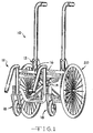
- a wheelchair 10 comprising a pair of longitudinally disposed side frame assemblies 12 arranged in a horizontally spaced parallel relation to one another.
- a cross-brace assembly 14 interconnects the side frame assemblies 12.
- Seat frame bars 16 are integral with the side frame assemblies 12.
- a seat assembly (not shown) is supported by the seat frame bars 16.
- the length and height of the seat assembly may be adjustable.
- Adjustable foot rests (not shown) may be selectively mounted to the side frame assemblies 12 to support the user's feet.
- the side frame assemblies 12 are supported on a supporting surface by adjustable front wheel assemblies 18 and adjustable rear wheel assemblies 20.
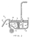
- each side frame assembly 12 includes a forward frame portion 24 and a rearward frame portion 26.
- the forward frame portion may be telescopically received by the rearward frame portion to define an adjustable component (not shown) for adjusting the length of the side frame assemblies.
- the side frame assemblies 12 further include upper and lower portions.
- the upper and lower portions of the side frame assemblies may include an upper horizontally extending bar 28 and a lower horizontally extending bar 30.
- forward upper and lower horizontally extending bars and seat frame bars may be telescopically received by rearward upper and lower horizontally extending bars and seat frame bars, respectively, to define the adjustable component for adjusting the length of the side frame assembly and seat frame bars.
- a side frame assembly length adjustment may include apertures in forward and rear side frame assembly upper and lower horizontally extending bars and seat frame bars through which a fastener may extend to fix a desired degree of telescopic movement or adjustment.
- the apertures may be set a predetermined distance apart to enable the side frame assemblies to be incrementally extended by the predetermined distance.
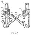
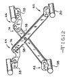
- the cross-brace assembly 14 shown is a folding mechanism including a first cross-brace member and a second cross-brace member, generally indicated as 38, connected by a pivot assembly 40.
- the side frame assemblies 12 are connected to the cross-brace assembly 14 by link assemblies 42, 44.
- Lower portions 46 of the first and second cross-brace members 38 are respectively connected to lower horizontally extending bars 30 of the side frame assemblies 12.
- a pivotal connection is shown between the cross-members and the lower link assemblies, it should be noted that a non-pivotal connection may be provided for non-folding wheelchairs (not shown).
- the position of the lower link assembly 42 on lower horizontally extending bar 30 of each side frame assembly 12 is fixed relative to the lower horizontally extending bar 30, such as by welding or in some other suitable fashion.
- the first and second cross-brace members 38 further include upper portions 52.
- the upper portions 52 of the first and second cross-brace members 38 are connected to the upper horizontally extending bars 28 of the side frame assemblies 12 by upper link assemblies 44.
- the position of the upper link assembly 44 on upper horizontally extending bar 28 of each side frame assembly 12 is fixed relative to upper horizontally extending bar 28, such as by welding or in some other suitable fashion in a manner similar to that of the lower link assembly 42 described above.
- the first and second cross-brace members could include apper and lower telescopically received portions and apertures along the upper and lower portions for receiving fasteners to enable the length of the cross-brace members to be adjusted.
- the focal point of the pivot assembly may be adjustable along the axis of each cross-brace member 38.
- the spacing between the side frame assemblies can be varied without regard to any adjustability of the cross-brace assembly.
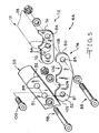
- the lower link assemblies 42 include a first member or first tab 58 and a second member or second tab 60.
- the first and second tabs 58, 60 are longitudinally spaced apart to provide a channel 62 between the first and second tabs 58, 60.
- the first and second tabs 58, 60 each include a first end 64 and a second end 66.
- the first end 64 of each tab 58, 60 is fixed to the lower horizontally extending bars 30, as described above.
- the second end 66 of each tab 58, 60 is provided with a plurality of horizontally spaced apertures 68. Although only three apertures are shown, any suitable number of apertures can be provided.
- the apertures 68 in the second end 66 of the first tab 58 co-align with the apertures 68 in the second end 66 of the second tab 60 to provide co-aligning pairs of apertures 68.
- Each co-aligning pair of apertures defines an adjustment point.
- the lower portions 46 of the cross-brace members 38 are received by the channel 62 formed between the tabs 58, 60.
- a cross-brace aperture 69 is provided in the lower portion 46 of each cross-brace member 38.
- a fastener 70 is received through a co-aligning pair of tab apertures 68 and the cross-brace aperture 69 in the lower portion 46 of each cross-brace member 38 to pivotally attach the cross-brace members 38 to the lower link assemblies 42.
- the spacing between the side frame assemblies 12 between the lower horizontally extending bars 30 may be varied.
- the horizontal distance between the tab apertures 68 of the lower link assemblies 42 may be a predetermined distance to enable a user to vary the spacing between the side frame assemblies by a predetermined amount.
- the distance between the tab apertures 68 of the lower link assemblies 42 may be uniformly spaced to enable the user to make uniformed incremental adjustments in the spacing between the side frame assemblies 12.
- the upper link assemblies 44 include a first member or tab 72 and a second member or bridge element 74.
- the tab 72 includes a first end 76 and a second end 78
- the bridge element 74 includes a first end 80 and a second end 82.
- the tab 72 of the upper link assemblies 44 can be identical to the first and second tabs 58, 60 of the lower link assemblies 42.
- the first end 76 of each upper link assembly tab 72 is fixed to the upper horizontally extending bar 28 of each side frame assembly 12, as described above.
- the second end 78 of the upper link assembly tab 72 is provided with a plurality of horizontally spaced upper tab apertures 84.
- each upper tab aperture 84 defines an adjustment point. Although only three apertures are shown, any number of suitable apertures can be provided.
- the first end 80 of the bridge element 74 is provided with a single aperture 85 which may be positioned to co-align with one of the horizontally spaced upper tab apertures 84 in the second end 78 of the upper link assembly tab 72.
- a fastener 88 is releaseably received through the co-aligning apertures 84, 85 to pivotally attach the first end 80 of the bridge element 74 to the second end 78 of the upper link assembly tab 72.
- the bridge element 74 is permitted to pivot about the fastener 88 and relative to the upper link assembly tab 72 and further, relative to the upper horizontally extending bar 28 of the side frame assemblies 12.
- the releasable fastener 88 may attach the bridge element 74 to the upper link assembly tab 72 through any one of the apertures 84, thus enabling the spacing between the side frame assemblies 12 between the upper horizontally extending bars 28 to be varied.
- the horizontal distance between the apertures 84 in the upper link assembly tab 72 can be a predetermined distance to enable a user to vary the spacing between the side frame assemblies 12 by a predetermined amount.
- the distance between the apertures 84 in the upper link assembly tab 72 may be uniformly spaced to enable the user the make uniformed incremental adjustments in the spacing between the side frame assemblies 72.
- the second end 82 of the bridge element 74 is likewise provided with a single aperture 87.
- the upper portion 52 of each cross-brace member 38 is provided with two apertures 89, 91 including an upper aperture 89 and an intermediate aperture 91.
- the intermediate cross-brace aperture 91 in the upper portion 52 of the cross-brace members 38 is positioned to align with the single aperture 87 in the second end 82 of the bridge member 74.
- a fastener 98 is received through the co-aligned apertures 87, 91 to pivotally attach the cross-brace members 38 to the second end 82 of the bridge element 74 of each upper link assembly 42.
- a stop pin 100 extends through the upper aperture 89 in the upper portion 52 of the cross-brace members 38.
- the stop pin 100 engages the bridge element 74 upon unfolding the wheelchair 10 to restrict the travel of the cross-brace members 38.
- the second end 82 of the bridge element 74 can be provided with a circumferential surface 102.
- the fastener pivotally 98 attaching the cross-brace members 38 to the bridge element 74 defines a focal point for the radius of the circumferential surface 102.
- the stop pin 100 travels along an arc about the circumferential surface 102.
- a first relief 104 is provided in an upper portion of the bridge element 74 proximate the second end 82 of the bridge element 74.
- the first relief 104 has a diameter which is suitable to receive the stop pin 100.
- a portion of the first relief 104 can be tangential to a portion of the outer circumferential surface 102.
- the stop pin 100 Upon unfolding the wheelchair 10, the stop pin 100 travels along the arc about the circumferential surface 102 into the first relief 104 which in part defines an abutment surface for the stop pin 100.
- the tangential portions of the first relief 104 and the circumferential surface 102 provide a smooth transition for the stop pin 100 to travel into and out of the first relief 104. It should be understood that the present invention is not limited to the use of a stop pin and that the travel of the cross-brace members 38 may be restricted by any suitable stop member.
- a second relief 106 is provided in an upper portion of the bridge element 74 proximate the first end 80 of the bridge element 74.
- the second relief 106 has a diameter suitable to receive the upper horizontally extending bar 28.
- the first end 80 of the bridge element 74 can have a circumferential surface 108 having a radius the focal point of which is the center of the aperture 85 in the first end 80 of the bridge element 74.
- the radius of the circumferential surface 108 at the first end 80 of the bridge element 74 is at least slightly less than distance between the focal point of the outermost aperture 84' in the upper link assembly tab 72 and the upper horizontally extending bar 28 to which upper link assembly tab 72 is attached.
- link assemblies 42, 44 can be staggered forwardly and rearwardly, as is clearly shown in Fig. 2. That is to say, one of the upper link assemblies 44 can be fixed to an upper horizontally extending bar 28 forwardly of the forward or first cross-brace member 38 and the other upper link assembly 44 can be fixed to the opposite upper horizontally extending bar 28 rearwardly of the rear or second cross-brace member 38'. Likewise, one of the lower link assemblies 42 can be fixed to a lower horizontally extending bar 30 forwardly of the forward or first cross-brace member 38 and the other lower link assembly 42 can be fixed to the opposite lower horizontally extending bar 30 rearwardly of the rearmost or second cross-brace member 38'. This configuration does not interfere with the folding and unfolding of the cross-brace assembly 14.
- the link assemblies 42, 44 can be arranged so that the bridge elements 74 co-aligned with one another. That is to say, one of the upper link assemblies 44 can be fixed to an upper horizontally extending bar 28 rearwardly of the forward or first cross-brace member 38 and the other upper link assembly 44 can be fixed to the opposite upper horizontally extending bar 28 forwardly of the rear or second cross-brace member 38'. Likewise, one of the lower link assemblies 42 can be fixed to a lower horizontally extending bar 30 rearwardly of the forward or first cross-brace member 38 and the other lower link assembly 42 can be fixed to the opposite lower horizontally extending bar 30 forwardly of the rearmost or second cross-brace member 38'.
- the spacing between the side frame assemblies 12 is varied by adjusting the link assemblies 42, 44 using horizontally spaced adjustment points in the upper link assemblies 44 that correspond with horizontally spaced adjustment points of the lower link assemblies 42.
- the spacing between the side frame assemblies 12 may be varied by adjusting the upper and lower link assemblies 44, 42 on one side, it is preferable that the upper and lower link assemblies 44, 42 on both sides be symmetrically adjusted. Because the upper link assemblies 44 are fixed to the upper horizontally extending bars 28 rather than the seat frame bar 16, the spacing between the side frame assemblies 12 may be adjusted without affecting the height of the seat assembly (not shown).
- the spacing between the side frame assemblies 12 is not varied by adjusting the length of the cross-brace members 38, so as to vary the angle between the cross-brace members 38, as in conventional wheelchairs, but rather the spacing between the side frame assemblies 12 is varied by making an adjustment to the link assemblies 42, 44.
- the adjustment substantially includes only a horizontal component, absent any substantial vertical adjustment component. Hence, the overall height of the wheelchair 10 remains unaffected by adjusting the width of the wheelchair 10.
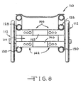
- a link assembly according to the present invention can be used on non-foldable wheelchairs 110.
- the link assembly can include opposed upper links 144 and opposed lower links 142.
- the lower links 142 can be attached to a lower portion 130 of the side frame assembly 112 and attached to one of the lower portions 146 of the cross-brace assembly 114.
- the upper links 144 can attach to an upper portion 128 of the side frame assembly 112 and attach to one of the upper portions 152 of the cross-brace assembly 114.
- the upper and lower links 144, 142 are each positionable substantially horizontally to vary the horizontal spacing between the side frame assemblies 112. No pivotal connection is required because the wheelchair 110 is a rigid or non-foldable wheelchair.
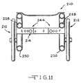
- a link assembly according to the present invention can be used on non-foldable wheelchairs 210 having a single cross-brace assembly 214.
- the link assembly can include a single pair of opposed links 244.
- the opposed links 144 can attach to a portion 228 of each side frame assembly 212 and attach to a upper portion 252 of the cross-brace assembly 214.
- the opposed links 144 are positionable substantially horizontally to vary the horizontal spacing between the side frame assemblies 212. No pivotal connection is required because the wheelchair 210 is a rigid or non-foldable wheelchair.
- One or more of the link assemblies 42, 44 and 142, 144, or a portion of the link assemblies 42, 44 and 142, 144, can be integral with the cross-brace assembly 14, 114 or the side frame assembly 12,112.
- a plurality of substantially spaced apart apertures 260 are provided in the cross-brace assembly 214 and a single aperture 268 is provided in the tabs 258, 260. This configuration would vary the spacing between the side frame assemblies 212 without varying the height of the seat frame bars (not shown).
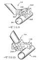
- two lower tabs 58, 60 are not required.
- a single tab 358 as shown in Fig. 10, will suffice to attach the cross-brace assembly 314 to the side frame assembly 312.
- the cross-brace assembly can be provided with a yoke 359 to engage the tab 358.
- the tab 72 can be provided with a single aperture 84 and the bridge element 74 can be provided with a plurality of substantially horizontally spaced apertures 85 to accomplished the same horizontal adjustment set forth above.
- the upper links 44, 144 can be suitable for attaching a lower portion 46, 146 of a cross-brace assembly 14, 114 to a lower portion 130 of a side frame assemblies 12, 112 and the lower links 42, 142 can be suitable for attaching an upper portion 52, 152 of the cross-brace assembly 14, 114 to an upper portion 28, 128 of the side frame assembly 12, 112.
Landscapes
- Health & Medical Sciences (AREA)
- Life Sciences & Earth Sciences (AREA)
- Animal Behavior & Ethology (AREA)
- General Health & Medical Sciences (AREA)
- Public Health (AREA)
- Veterinary Medicine (AREA)
- Handcart (AREA)
- Carriages For Children, Sleds, And Other Hand-Operated Vehicles (AREA)
- Chair Legs, Seat Parts, And Backrests (AREA)
Claims (16)
- Verbindungsbaugruppe zum Verbinden einer Querverstrebungsbaugruppe (14, 144) eines Rollstuhls (10, 110) mit horizontal eingeteilten Seitenrahmenbaugruppen (12, 112) des Rollstuhls, wobei die Querverstrebungsbaugruppe (14, 144) obere Teile (52, 152) und untere Teile (46, 146) umfasst und die Seitenrahmenbaugruppen (12, 112) jeweils einen oberen Teil (28, 128) und einen unteren Teil (30, 130) aufweisen, wobei die Verbindungsbaugruppe umfasst:gegenüberliegende obere Verbindungen, die jeweils an einem der oberen Teile (28, 128) der Seitenrahmenbaugruppen (12, 112) und an einem der oberen Teile (52, 152) der Querverstrebungsbaugruppe (14, 144) befestigt sind; undgegenüberliegende untere Verbindungen, die jeweils an einem der unteren Teile (30, 130) der Seitenrahmenbaugruppen (12, 112) und an einem der unteren Teile (46, 146) der Querverstrebungsbaugruppe (14, 144) befestigt sind, wobei die Verbindungsbaugruppe dadurch gekennzeichnet ist, dass:jede obere Verbindung ferner im Wesentlichen horizontal so verstellbar ist, dass nur der horizontale Abstand zwischen den oberen Teilen (28, 128) der Seitenrahmenbaugruppen (12, 112) zu variieren ist, ohne die vertikale Position der Seitenrahmenbaugruppen (12, 112) zu beeinflussen; undjede untere Verbindung ferner im Wesentlichen horizontal so verstellbar ist, dass nur der horizontale Abstand zwischen den unteren Teilen (30, 130) der Seitenrahmenbaugruppen (12, 112) zu variieren ist, ohne die vertikale Position der Seitenrahmenbaugruppen (12, 112) zu beeinflussen.
- Verbindungsbaugruppe gemäß Anspruch 1, des Weiteren beinhaltend Stoppelement (100), um den Drehweg der oberen Teile (52) der Querverstrebungsbaugruppe (14) zu begrenzen.
- Verbindungsbaugruppe zum Verbinden einer Querverstrebungsbaugruppe (14) eines faltbaren Rollstuhls (10) mit horizontal eingeteilten Seitenrahmenbaugruppen (12) des Rollstuhls (10), wobei die Querverstrebungsbaugruppe (14) obere Teile (52) und untere Teile (46) umfasst und die Seitenrahmenbaugruppen (12) jeweils einen oberen Teil und einen unteren Teil aufweisen, und die Verbindungsbaugruppe umfasst:gegenüberliegende obere Verbindungen, die jeweils an einem der oberen Teile der Seitenrahmenbaugruppen (12) befestigt und drehbar mit einem der oberen Teile (52) der Querverstrebungsbaugruppe (14) verbunden sind; undgegenüberliegende untere Verbindungen, die jeweils an einem der unteren Teile der Seitenrahmenbaugruppen (12) befestigt und drehbar mit einem der unteren Teile (46) der Querverstrebungsbaugruppe (14) verbunden sind, wobei die Verbindungsbaugruppe dadurch gekennzeichnet ist, dass:jede obere Verbindung ferner im Wesentlichen horizontal so verstellbar ist, dass nur der horizontale Abstand zwischen den oberen Teilen der Seitenrahmenbaugruppen (12) zu variieren ist, ohne die vertikale Position der Seitenrahmenbaugruppen (12) zu beeinflussen; undjede untere Verbindung ferner im Wesentlichen horizontal so verstellbar ist, dass nur der horizontale Abstand zwischen den unteren Teilen der Seitenrahmenbaugruppen (12) zu variieren ist, ohne die vertikale Position der Seitenrahmenbaugruppen (12) zu beeinflussen.
- Verbindungsbaugruppe gemäß Anspruch 3, des Weiteren beinhaltend Stoppelement (100) zum Begrenzen des Drehweg der oberen Querverstrebungsbaugruppe (14).
- Verbindungsbaugruppe gemäß Anspruch 3, bei der jede obere Verbindung ferner ein Entlastungselement (106) umfasst, das eine komplementäre Form zu einem entsprechenden oberen Teil der Seitenrahmenbaugruppe (12) des Rollstuhls (10) in der Nähe der Stelle aufweist, wo die obere Verbindung am oberen Teil der Seitenrahmenbaugruppe (12) des Rollstuhls (10) befestigt ist, und das Entlastungselement (106) den entsprechenden oberen Teil der Seitenrahmenbaugruppe (12) des Rollstuhls (10) beim Falten des Rollstuhls (10) aufnimmt.
- Verbindungsbaugruppe gemäß Anspruch 3, bei der jede obere Verbindung ferner ein erstes Bauelement (72) und ein zweites Bauelement (74) umfasst, wobei das erste Bauelement (72) jeder oberen Verbindung an einem oberen Teil einer entsprechenden Seitenrahmenbaugruppe (12) des Rollstuhls (10) befestigt ist und das zweite Bauelement (74) jeder oberen Verbindung drehbar mit einem entsprechenden oberen Teil (52) der Querverstrebungsbaugruppe (14) des Rollstuhls (10) verbunden ist, wobei das erste Bauelement (72) jeder oberen Verbindung lösbar und drehbar mit dem zweiten Bauelement (74) einer der entsprechenden oberen Verbindungen zu verbinden ist und so einen Befestigungspunkt bildet, wobei das erste Bauelement (72) jeder oberen Verbindung ferner mit einer Vielzahl von Öffnungen mit horizontalem Abstand (84) zueinander ausgestattet ist, darin eine Vielzahl von Punkten mit horizontalem Abstand definierend, wobei die Öffnungen (84) sich innerhalb einer gemeinsamen, im Wesentlichen horizontalen Ebene befinden und die Verbindungsbaugruppe (44) ferner ein lösbares Befestigungselement (88) zum drehbaren Verbinden des zweiten Bauelements (74) jeder oberen Verbindung mit dem ersten Bauelement (72) einer der entsprechenden oberen Verbindungen durch eine aus der Vielzahl von Öffnungen mit horizontalem Abstand (84) beinhaltet.
- Verbindungsbaugruppe gemäß Anspruch 6, bei der jede untere Verbindung femer ein erstes Bauelement (58) und ein zweites Bauelement (60) umfasst, wobei das erste Bauelement (58) und das zweite Bauelement (60) einen Abstand zueinander aufweisen und jedes Bauelement (58, 60) mit einer Vielzahl von Öffnungen (68) mit im Wesentlichen horizontalem Abstand ausgestattet ist, darin eine Vielzahl von Punkten mit im Wesentlichen horizontalem Abstand definierend, wobei jede der Öffnungen (68) im ersten Bauelement (58) mit einer entsprechenden Öffnung (68) im zweiten Bauelement (60) fluchtet und so eine Vielzahl von Sätzen einander entsprechender Öffnungen gebildet wird, wobei jeder Satz sich entsprechender Öffnungen (68) im ersten Bauelement (58) und im zweiten Bauelement (60) und die entsprechenden Öffnungen (84) der ersten Bauelemente (72) der oberen Verbindung so angeordnet sind, dass sie sich in einer gemeinsamen, im Wesentlichen vertikalen Ebene befinden.
- Verbindungsbaugruppe gemäß Anspruch 3, bei der jede der gegenüber angeordneten oberen Verbindungen eine Lasche (72) und ein Brückenelement (74) umfasst, wobei die Lasche (72) ein erstes Ende (76) und ein zweites Ende (78) umfasst, das Brückenelement (74) ein erstes Ende (80) und ein zweites Ende (82) umfasst, das erste Ende (76) der Lasche (72) jeder oberen Verbindung mit einem oberen Teil einer entsprechenden Seitenrahmenbaugruppe (12) des Rollstuhls (10) verbunden ist, das zweite Ende (78) der Lasche (72) jeder oberen Verbindung lösbar und drehbar mit dem ersten Ende (80) des Brückenelements (74) einer der entsprechenden oberen Verbindungen mit einem aus einer Vielzahl von Einstellpunkte definierenden Punkten mit im Wesentlichen horizontalem Abstand verbunden ist und das zweite Ende (82) des Brückenelements (74) drehbar mit einem oberen Teil der Querverstrebungsbaugruppe (14) des Rollstuhls (10) verbunden ist; und
die gegenüber angeordneten unteren Verbindungen mindestens eine erste Lasche (58) umfassen, wobei die Lasche (58) der unteren Verbindung ein erstes Ende (64) und ein zweites Ende (66) umfasst, das erste Ende (64) der Lasche (58) jeder unteren Verbindung mit einem unteren Teil einer entsprechenden
Seitenrahmenbaugruppe (12) des Rollstuhls (10) verbunden ist, das zweite Ende (66) jeder unteren Verbindung lösbar und drehbar mit einem entsprechenden unteren Teil der Querverstrebungsbaugruppe (14) des Rollstuhls (10) an einem aus einer Vielzahl von Punkten mit im Wesentlichen horizontalem Abstand verbunden ist, und jeder der mit Abstand angeordneten Punkte der unteren Verbindungen einem der mit Abstand angeordneten Punkte der oberen Verbindungen entspricht und so eine Vielzahl von Sätzen einander entsprechender Punkte zur Verfügung stellen, wobei jeder Satz sich entsprechender Punkte sich auf einer gemeinsamen, im Wesentlichen vertikalen Ebene befindet. - Faltbarer Rollstuhl (10), umfassend:Verbindungsbaugruppe (42, 44), die die Querverstrebungsbaugruppe (14) mit zwei Seitenrahmenbaugruppen (12) verbindet, wobei die Verbindungsbaugruppe (42, 44) umfasst:Querverstrebungsbaugruppe (14), umfassend:obere Teile (52) und untere Teile (46);zwei Seitenrahmenbaugruppen (12), jeweils umfassend:einen oberen Teil und einen unteren Teil; undgegenüberliegende obere Verbindungen, die jeweils mit einem der oberen Teile der Seitenrahmenbaugruppen (12) verbunden und drehbar mit einem der oberen Teile (52) der Querverstrebungsbaugruppe (14) verbunden sind; undgegenüberliegende untere Verbindungen, die jeweils mit einem der unteren Teile der Seitenrahmenbaugruppen (12) verbunden und drehbar mit einem der unteren Teile (46) der Querverstrebungsbaugruppe (14) verbunden sind, wobei die Verbindungsbaugruppe dadurch gekennzeichnet ist, dass:jede obere Verbindung ferner im Wesentlichen horizontal so verstellbar ist, dass nur der horizontale Abstand zwischen den oberen Teilen der Seitenrahmenbaugruppen (12) zu variieren ist, ohne die vertikale Position der Seitenrahmenbaugruppen (12) zu beeinflussen; undjede untere Verbindung ferner im Wesentlichen horizontal so verstellbar ist, dass nur der horizontale Abstand zwischen den unteren Teilen der Seitenrahmenbaugruppen (12) zu variieren ist, ohne die vertikale Position der Seitenrahmenbaugruppen (12) zu beeinflussen.
- Faltbarer Rollstuhl gemäß Anspruch 9, bei dem
der obere Teil jeder Seitenrahmenbaugruppe (12) eine obere, sich horizontal erstreckende Strebe (28) und der untere Teil jeder Seitenrahmenbaugruppe (12) eine untere, sich horizontal erstreckende Strebe (30) beinhaltet, wobei die horizontal sich erstreckenden Streben (28, 30) mit vertikalem Abstand angeordnet und relativ zueinander fixiert sind, und jede obere Verbindung mit der oberen, sich horizontal erstreckenden Strebe (28) einer der entsprechenden Seitenrahmenbaugruppen (12) und die unteren Verbindungen mit der unteren, sich horizontal erstreckenden Strebe (30) einer der entsprechenden Seitenrahmenbaugruppen (12) verbunden ist. - Faltbarer Rollstuhl gemäß Anspruch 9, ferner beinhaltend:Stoppelement (100), um den Drehweg der Querverstrebungsbaugruppe (14) zu begrenzen.
- Faltbarer Rollstuhl gemäß Anspruch 9, bei dem
jeder obere Teil der Querverstrebungsbaugruppe (14) einen Anschlagstift (100) beinhaltet, wobei sich der Anschlagstift (100) ferner entlang eines Bogens mit vordefiniertem Radius bewegt; und .
die obere Verbindung ferner eine Umfangsfläche (102) mit vorbestimmtem Radius umfasst, der so dimensioniert ist, dass der Bogenweg des Anschlagstifts nicht beeinträchtigt wird, wobei der Radius des Bogenwegs des Anschlagstifts (100) und der Radius der Umfangsfläche (102) einen gemeinsamen Bezugspunkt besitzen. - Faltbarer Rollstuhl gemäß Anspruch 12, bei dem
der Anschlagstift (100) einen Außenradius besitzt, und
die obere Verbindung ferner ein Entlastungselement (104) mit einer Anschlagfläche umfasst, um den Weg des Anschlagstifts (100) zu begrenzen, wobei das Entlastungselement (104) ferner einen ersten Teil mit einem Radius aufweist, der zum Außenradius des Anschlagstifts (100) komplementär ist, und einen zweiten Teil mit einem Radius aufweist, dessen Endseite tangential zur Endseite des Radius der Umfangsfläche (102) ist, um für den Anschlagstift (100) einen weichen Übergang für den Weg zwischen dem Entlastungselement (104) und der Umfangsfläche (102) zur Verfügung zu stellen. - Faltbarer Rollstuhl gemäß Anspruch 9, bei dem
jede obere Verbindung ferner ein Entlastungselement (106) mit einer Form umfasst, die komplementär ist zum entsprechenden oberen Teil der Seitenrahmenbaugruppen (12)
in der Nähe der Stelle, wo das obere Verbindungselement mit dem oberen Teil verbunden ist, wobei das Entlastungselement (106) den entsprechenden oberen Teil der Seitenrahmenbaugruppen (12) beim Falten des faltbaren Rollstuhls (10) in eine kompakte Form aufnimmt. - Faltbarer Rollstuhl gemäß Anspruch 14, bei dem
jeder obere Teil der Seitenrahmenbaugruppen (12) ein röhrenförmiges Bauelement (28) mit vorbestimmtem Außenradius umfasst, und jedes Entlastungselement (106) einen Innenradius umfasst, der zum Außenradius eines der entsprechenden oberen Teile der Seitenrahmenbaugruppen (12) komplementär ist. - Faltbarer Rollstuhl gemäß Anspruch 9, bei dem
jede obere Verbindung ferner eine Lasche (72) und ein Brückenelement (74) umfasst, wobei die Lasche (72) jeder oberen Verbindung mit einem oberen Teil einer der entsprechenden Seitenrahmenbaugruppen (12) verbunden ist und jedes Brückenelement (74) jeder oberen Verbindung drehbar mit dem entsprechenden Teil der Querverstrebungsbaugruppe (14) verbunden ist, jede Lasche (72) jeder der oberen Verbindungen lösbar und drehbar mit dem Brückenelement (74) jeder der oberen Verbindungen zu verbinden ist, so den Drehpunkt bildend, die Lasche (72) jeder oberen Verbindung mit einer Vielzahl von Öffnungen (84) mit horizontalem Abstand ausgestattet ist, darin eine Vielzahl Punkten mit im Wesentlichen horizontalem Abstand definierend, und das Brückenelement (74) jeder oberen Verbindung mit mindestens einer Öffnung (85) ausgestattet ist, die so positioniert werden kann, dass sie mit den Öffnungen (84) in der Lasche (72) fluchtet,
und der Rollstuhl des Weiteren umfasst:lösbares Befestigungselement (88) zum Verbinden der Öffnung (85) im Brückenelement (74) mit einer der Öffnungen (84) in der Lasche (72), die mit der Öffnung (88) im Brückenelement (74) fluchtet.
Applications Claiming Priority (3)
| Application Number | Priority Date | Filing Date | Title |
|---|---|---|---|
| US2860298A | 1998-02-24 | 1998-02-24 | |
| US28602 | 1998-02-24 | ||
| PCT/US1999/003800 WO1999043530A1 (en) | 1998-02-24 | 1999-02-22 | Wheelchair and link assembly for use with a wheelchair |
Publications (3)
| Publication Number | Publication Date |
|---|---|
| EP1056635A1 EP1056635A1 (de) | 2000-12-06 |
| EP1056635A4 EP1056635A4 (de) | 2001-12-12 |
| EP1056635B1 true EP1056635B1 (de) | 2004-11-10 |
Family
ID=21844361
Family Applications (1)
| Application Number | Title | Priority Date | Filing Date |
|---|---|---|---|
| EP99936054A Expired - Lifetime EP1056635B1 (de) | 1998-02-24 | 1999-02-22 | Rollstuhl sowie an einem rollstuhl zu gebrauchende verbindungseinrichtung |
Country Status (9)
| Country | Link |
|---|---|
| US (1) | US6227559B1 (de) |
| EP (1) | EP1056635B1 (de) |
| AU (1) | AU3305399A (de) |
| CA (1) | CA2319826A1 (de) |
| DE (1) | DE69921783T2 (de) |
| ES (1) | ES2229747T3 (de) |
| NO (1) | NO320831B1 (de) |
| NZ (1) | NZ505928A (de) |
| WO (1) | WO1999043530A1 (de) |
Families Citing this family (15)
| Publication number | Priority date | Publication date | Assignee | Title |
|---|---|---|---|---|
| US6883819B2 (en) * | 2001-01-23 | 2005-04-26 | Marvin Byrd | Companion rider wheel chair |
| JP3993996B2 (ja) * | 2001-10-23 | 2007-10-17 | 株式会社ミキ | 車椅子 |
| GB0207144D0 (en) * | 2002-03-27 | 2002-05-08 | Specmat Ltd | Wheelchairs |
| TW556540U (en) * | 2002-04-03 | 2003-10-01 | Aidc Aerospace Ind Dev Corp | Modulized structure of wheelchair |
| US20060131833A1 (en) * | 2003-03-27 | 2006-06-22 | Specmat Limited | Wheelchairs |
| US7198284B2 (en) * | 2004-04-07 | 2007-04-03 | Invacare Corporation | Adjustable personal mobility aid |
| US6938911B1 (en) * | 2004-06-14 | 2005-09-06 | Hanlong Industrial Co., Ltd. | Folding wheelchair |
| US7384058B2 (en) * | 2005-01-05 | 2008-06-10 | Ki Mobility Llc | Foldable wheelchair with extensible link assembly and method |
| US20060237943A1 (en) * | 2005-04-20 | 2006-10-26 | Eric Lai | Structure of a wheelchair |
| ITPD20060209A1 (it) * | 2006-05-24 | 2007-11-25 | Vassilli Srl | Carrozzina registrabile per bambini disabili |
| US8628108B2 (en) * | 2008-04-28 | 2014-01-14 | Motion Composites Inc. | Light weight foldable and customizable wheelchair |
| US8157287B1 (en) * | 2010-10-21 | 2012-04-17 | Cleveland Valerie N | Convertible wheelchair |
| DE102011050800B4 (de) | 2011-06-01 | 2013-03-07 | Sunrise Medical Gmbh & Co. Kg | Rollstuhl, Kreuzstrebenanordnung für einen Rollstuhl und Verfahren zur Einstellung des Seitenrahmenabstandes |
| US12370100B1 (en) * | 2021-06-04 | 2025-07-29 | Ki Mobility Llc | Wheelchair frame folding mechanism |
| CA3168572C (en) | 2022-07-13 | 2025-08-05 | Invacare Corporation | WHEELCHAIR AND SUSPENSION SYSTEMS |
Family Cites Families (7)
| Publication number | Priority date | Publication date | Assignee | Title |
|---|---|---|---|---|
| US3122395A (en) * | 1961-02-07 | 1964-02-25 | Offner Edwin | Width-adjusting attachment for wheel chairs |
| US4082348A (en) * | 1976-03-01 | 1978-04-04 | Invacare Corporation | Adjustable wheel chair |
| US4813693A (en) | 1986-09-30 | 1989-03-21 | Invacare Corporation | Adjustable child's wheelchair |
| US4989890A (en) | 1986-09-30 | 1991-02-05 | Invacare Corporation | Length and width adjustable wheelchair |
| US5328183A (en) * | 1992-11-05 | 1994-07-12 | Quickie Designs Inc. | Folding wheelchair frame |
| US5915709A (en) * | 1996-11-12 | 1999-06-29 | Invacare Corporation | Modular cross member assembly for adjustable wheelchair |
| DE19742267C2 (de) * | 1997-09-25 | 1999-10-21 | Bock Orthopaed Ind | Kreuzstrebe für einen Faltrollstuhl |
-
1999
- 1999-02-22 AU AU33053/99A patent/AU3305399A/en not_active Abandoned
- 1999-02-22 NZ NZ505928A patent/NZ505928A/xx unknown
- 1999-02-22 EP EP99936054A patent/EP1056635B1/de not_active Expired - Lifetime
- 1999-02-22 DE DE69921783T patent/DE69921783T2/de not_active Expired - Lifetime
- 1999-02-22 ES ES99936054T patent/ES2229747T3/es not_active Expired - Lifetime
- 1999-02-22 WO PCT/US1999/003800 patent/WO1999043530A1/en not_active Ceased
- 1999-02-22 CA CA002319826A patent/CA2319826A1/en not_active Abandoned
-
2000
- 2000-01-07 US US09/479,537 patent/US6227559B1/en not_active Expired - Lifetime
- 2000-08-23 NO NO20004209A patent/NO320831B1/no unknown
Also Published As
| Publication number | Publication date |
|---|---|
| NO20004209D0 (no) | 2000-08-23 |
| DE69921783T2 (de) | 2005-03-24 |
| EP1056635A1 (de) | 2000-12-06 |
| WO1999043530A1 (en) | 1999-09-02 |
| DE69921783D1 (de) | 2004-12-16 |
| CA2319826A1 (en) | 1999-09-02 |
| NO20004209L (no) | 2000-08-23 |
| NZ505928A (en) | 2003-03-28 |
| NO320831B1 (no) | 2006-01-30 |
| ES2229747T3 (es) | 2005-04-16 |
| US6227559B1 (en) | 2001-05-08 |
| AU3305399A (en) | 1999-09-15 |
| EP1056635A4 (de) | 2001-12-12 |
Similar Documents
| Publication | Publication Date | Title |
|---|---|---|
| EP1056635B1 (de) | Rollstuhl sowie an einem rollstuhl zu gebrauchende verbindungseinrichtung | |
| US5593173A (en) | Vertical folding wheelchair frame | |
| US4981305A (en) | Symmetrically modular wheelchair | |
| EP0777454B1 (de) | Faltbarer rollstuhl | |
| US4861056A (en) | Folding wheelchair with improved frame and suspension system | |
| US4082348A (en) | Adjustable wheel chair | |
| US4648619A (en) | Collapsible wheelchair chassis | |
| US6302429B1 (en) | Convertible wheelchair | |
| US5253888A (en) | Rigid frame weldless wheelchair | |
| US7360781B2 (en) | Foldable wheelchair and axle plate therefor | |
| US7021640B2 (en) | Wheelchair and wheel mounting assembly therefore | |
| US5480179A (en) | Wheelchair chassis | |
| CA2370794A1 (en) | Wheelchair frame | |
| US4652005A (en) | Lightweight wheelchair | |
| US20110018222A1 (en) | Caster Strut, Wheelchair Frame and Wheelchair | |
| US6345833B2 (en) | Two-piece side frame assembly for small wheelchairs | |
| US7419182B2 (en) | Mobility aid | |
| EP1522296A2 (de) | Modularer Gestellrahmen für ein Rollstuhl | |
| CA1311676C (en) | Foldable wheelchair | |
| EP1824724B1 (de) | Zusammenklappbarer rollstuhl und achsplatte dafür | |
| US5248158A (en) | Sidecar for bicycles | |
| EP0807427B1 (de) | Modular Rollstuhl | |
| EP1097689A2 (de) | Verstellbare Platte zur Befestigung an den Sitzseiten, ausgestattet mit einer Rückenlehne und Zubehör, insbesondere zur Verwendung für Behindertenrollstühle, sowie Rollstühle, die mit diesem System hergestellt wurden | |
| CA2219862A1 (en) | Wheelchairs | |
| MXPA97008520A (en) | Rue chairs |
Legal Events
| Date | Code | Title | Description |
|---|---|---|---|
| PUAI | Public reference made under article 153(3) epc to a published international application that has entered the european phase |
Free format text: ORIGINAL CODE: 0009012 |
|
| 17P | Request for examination filed |
Effective date: 20000728 |
|
| AK | Designated contracting states |
Kind code of ref document: A1 Designated state(s): BE CH DE DK ES FR GB IT LI NL SE |
|
| RIN1 | Information on inventor provided before grant (corrected) |
Inventor name: FREUND, EDWARD, F. Inventor name: SLAGERMAN, MURRAY, G. |
|
| A4 | Supplementary search report drawn up and despatched |
Effective date: 20011029 |
|
| AK | Designated contracting states |
Kind code of ref document: A4 Designated state(s): BE CH DE DK ES FR GB IT LI NL SE |
|
| 17Q | First examination report despatched |
Effective date: 20030812 |
|
| GRAP | Despatch of communication of intention to grant a patent |
Free format text: ORIGINAL CODE: EPIDOSNIGR1 |
|
| GRAS | Grant fee paid |
Free format text: ORIGINAL CODE: EPIDOSNIGR3 |
|
| GRAA | (expected) grant |
Free format text: ORIGINAL CODE: 0009210 |
|
| AK | Designated contracting states |
Kind code of ref document: B1 Designated state(s): BE CH DE DK ES FR GB IT LI NL SE |
|
| PG25 | Lapsed in a contracting state [announced via postgrant information from national office to epo] |
Ref country code: LI Free format text: LAPSE BECAUSE OF FAILURE TO SUBMIT A TRANSLATION OF THE DESCRIPTION OR TO PAY THE FEE WITHIN THE PRESCRIBED TIME-LIMIT Effective date: 20041110 Ref country code: CH Free format text: LAPSE BECAUSE OF FAILURE TO SUBMIT A TRANSLATION OF THE DESCRIPTION OR TO PAY THE FEE WITHIN THE PRESCRIBED TIME-LIMIT Effective date: 20041110 Ref country code: BE Free format text: LAPSE BECAUSE OF FAILURE TO SUBMIT A TRANSLATION OF THE DESCRIPTION OR TO PAY THE FEE WITHIN THE PRESCRIBED TIME-LIMIT Effective date: 20041110 |
|
| REG | Reference to a national code |
Ref country code: GB Ref legal event code: FG4D |
|
| REG | Reference to a national code |
Ref country code: CH Ref legal event code: EP |
|
| REG | Reference to a national code |
Ref country code: SE Ref legal event code: TRGR |
|
| REF | Corresponds to: |
Ref document number: 69921783 Country of ref document: DE Date of ref document: 20041216 Kind code of ref document: P |
|
| REG | Reference to a national code |
Ref country code: DK Ref legal event code: T3 |
|
| REG | Reference to a national code |
Ref country code: ES Ref legal event code: FG2A Ref document number: 2229747 Country of ref document: ES Kind code of ref document: T3 |
|
| REG | Reference to a national code |
Ref country code: CH Ref legal event code: PL |
|
| PLBE | No opposition filed within time limit |
Free format text: ORIGINAL CODE: 0009261 |
|
| STAA | Information on the status of an ep patent application or granted ep patent |
Free format text: STATUS: NO OPPOSITION FILED WITHIN TIME LIMIT |
|
| ET | Fr: translation filed | ||
| 26N | No opposition filed |
Effective date: 20050811 |
|
| PGFP | Annual fee paid to national office [announced via postgrant information from national office to epo] |
Ref country code: FR Payment date: 20060217 Year of fee payment: 8 |
|
| PG25 | Lapsed in a contracting state [announced via postgrant information from national office to epo] |
Ref country code: SE Free format text: LAPSE BECAUSE OF NON-PAYMENT OF DUE FEES Effective date: 20070223 |
|
| PGFP | Annual fee paid to national office [announced via postgrant information from national office to epo] |
Ref country code: ES Payment date: 20070226 Year of fee payment: 9 |
|
| PGFP | Annual fee paid to national office [announced via postgrant information from national office to epo] |
Ref country code: DK Payment date: 20070228 Year of fee payment: 9 |
|
| EUG | Se: european patent has lapsed | ||
| REG | Reference to a national code |
Ref country code: FR Ref legal event code: ST Effective date: 20071030 |
|
| PGFP | Annual fee paid to national office [announced via postgrant information from national office to epo] |
Ref country code: SE Payment date: 20060227 Year of fee payment: 8 |
|
| PG25 | Lapsed in a contracting state [announced via postgrant information from national office to epo] |
Ref country code: FR Free format text: LAPSE BECAUSE OF NON-PAYMENT OF DUE FEES Effective date: 20070228 |
|
| REG | Reference to a national code |
Ref country code: DK Ref legal event code: EBP |
|
| PG25 | Lapsed in a contracting state [announced via postgrant information from national office to epo] |
Ref country code: DK Free format text: LAPSE BECAUSE OF NON-PAYMENT OF DUE FEES Effective date: 20080229 |
|
| REG | Reference to a national code |
Ref country code: ES Ref legal event code: FD2A Effective date: 20080223 |
|
| PG25 | Lapsed in a contracting state [announced via postgrant information from national office to epo] |
Ref country code: ES Free format text: LAPSE BECAUSE OF NON-PAYMENT OF DUE FEES Effective date: 20080223 |
|
| REG | Reference to a national code |
Ref country code: DE Ref legal event code: R082 Ref document number: 69921783 Country of ref document: DE Representative=s name: JONES DAY RECHTSANWAELTE PATENTANWAELTE, DE Effective date: 20130117 Ref country code: DE Ref legal event code: R081 Ref document number: 69921783 Country of ref document: DE Owner name: SUNRISE MEDICAL LTD., BRIERLEY HILL, GB Free format text: FORMER OWNER: SUNRISE MEDICAL HHG INC., LONGMONT, COL., US Effective date: 20130117 Ref country code: DE Ref legal event code: R081 Ref document number: 69921783 Country of ref document: DE Owner name: SUNRISE MEDICAL LTD., GB Free format text: FORMER OWNER: SUNRISE MEDICAL HHG INC., LONGMONT, US Effective date: 20130117 |
|
| REG | Reference to a national code |
Ref country code: NL Ref legal event code: SD Effective date: 20130507 |
|
| PGFP | Annual fee paid to national office [announced via postgrant information from national office to epo] |
Ref country code: NL Payment date: 20180221 Year of fee payment: 20 |
|
| PGFP | Annual fee paid to national office [announced via postgrant information from national office to epo] |
Ref country code: DE Payment date: 20180221 Year of fee payment: 20 Ref country code: GB Payment date: 20180221 Year of fee payment: 20 |
|
| PGFP | Annual fee paid to national office [announced via postgrant information from national office to epo] |
Ref country code: IT Payment date: 20180221 Year of fee payment: 20 |
|
| REG | Reference to a national code |
Ref country code: DE Ref legal event code: R071 Ref document number: 69921783 Country of ref document: DE |
|
| REG | Reference to a national code |
Ref country code: NL Ref legal event code: MK Effective date: 20190221 |
|
| REG | Reference to a national code |
Ref country code: GB Ref legal event code: PE20 Expiry date: 20190221 |
|
| PG25 | Lapsed in a contracting state [announced via postgrant information from national office to epo] |
Ref country code: GB Free format text: LAPSE BECAUSE OF EXPIRATION OF PROTECTION Effective date: 20190221 |