EP1056640B1 - Rotor a vitesse optimale - Google Patents
Rotor a vitesse optimale Download PDFInfo
- Publication number
- EP1056640B1 EP1056640B1 EP99934271A EP99934271A EP1056640B1 EP 1056640 B1 EP1056640 B1 EP 1056640B1 EP 99934271 A EP99934271 A EP 99934271A EP 99934271 A EP99934271 A EP 99934271A EP 1056640 B1 EP1056640 B1 EP 1056640B1
- Authority
- EP
- European Patent Office
- Prior art keywords
- rotor
- blade
- providing
- rpm
- helicopter
- Prior art date
- Legal status (The legal status is an assumption and is not a legal conclusion. Google has not performed a legal analysis and makes no representation as to the accuracy of the status listed.)
- Expired - Lifetime
Links
Images



Classifications
-
- B—PERFORMING OPERATIONS; TRANSPORTING
- B64—AIRCRAFT; AVIATION; COSMONAUTICS
- B64C—AEROPLANES; HELICOPTERS
- B64C27/00—Rotorcraft; Rotors peculiar thereto
- B64C27/32—Rotors
- B64C27/46—Blades
- B64C27/467—Aerodynamic features
-
- B—PERFORMING OPERATIONS; TRANSPORTING
- B64—AIRCRAFT; AVIATION; COSMONAUTICS
- B64C—AEROPLANES; HELICOPTERS
- B64C27/00—Rotorcraft; Rotors peculiar thereto
- B64C27/04—Helicopters
-
- Y—GENERAL TAGGING OF NEW TECHNOLOGICAL DEVELOPMENTS; GENERAL TAGGING OF CROSS-SECTIONAL TECHNOLOGIES SPANNING OVER SEVERAL SECTIONS OF THE IPC; TECHNICAL SUBJECTS COVERED BY FORMER USPC CROSS-REFERENCE ART COLLECTIONS [XRACs] AND DIGESTS
- Y10—TECHNICAL SUBJECTS COVERED BY FORMER USPC
- Y10S—TECHNICAL SUBJECTS COVERED BY FORMER USPC CROSS-REFERENCE ART COLLECTIONS [XRACs] AND DIGESTS
- Y10S416/00—Fluid reaction surfaces, i.e. impellers
- Y10S416/05—Variable camber or chord length
Definitions
- This invention relates to helicopters having variable speed rotors and to methods of improving efficiency, for example by achieving substantial increases in endurance, range, altitude and speed and reductions in noise levels and fuel consumption.
- the efficiency of an aircraft is directly proportional to the power required to achieve such performance.
- the power required is inversely proportional to the ratio of the aircraft lift to the draft (L/D).
- designers strive to increase the lift to draft ratio by minimizing the aircraft draft at lift levels required to counter the aircraft weight and to allow for aircraft manoeuvring.
- r is the air density
- V is the air velocity (airspeed)
- S is the reference area of the lifting surface (wing or rotor blade)
- C L and C D are non-dimensional lift and draft coefficients.
- the lift to drag ratio L/D is equal to coefficient of lift to the coefficient of drag ratio C L /C D .
- C L /C D has a direct effect on performance.
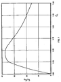
- the C L /C D is a function of C L as can be seen by the C L V. /C L /C D graph depicted in Figure 1 for a typical airfoil. For best cruise efficiency, the coefficient of lift of the lifting airfoil should be maintained at levels of maximum C L /C D .
- V r 2 ⁇ ( RPM ) 60 where, V r is the rotational speed and r is the radial distance measured from the rotor centre.
- a helicopter in a substantial forward speed experiences problems of control, vibration and limitations in performance resulting in the asymmetry in the speeds of the advancing and retreating blades.
- the advancing blade 10 When travelling in a forward direction 8, the advancing blade 10 has a speed equal the rotational speed of the blade plus the forward speed of the helicopter, whereas the retreating blade 12 has a speed equal the rotational speed of the blade minus the forward speed of the helicopter.
- the speeds along the length of the blades when travelling forward are shown in Figure 2.
- the advancing blade has more lift than the retreating blade.
- the lift on the retreating blade has to be increased while the speed on the advancing blade has to be decreased.
- the maximum allowable tip speed is typically lower than the speed of sound (ie Mach 1) so as to avoid the substantial increases in draft, vibration and noise encountered when the tip speed approaches Mach 1.
- a frequency that gives rise to an excitation frequency that occurs at a rate of 2 per revolution is referred to herein as the "2 per revolution" frequency.
- conventional rotors with any number of blades are designed to avoid the frequencies of 1 per revolution, 2 per revolution, 3 per revolution and so forth.
- Conventional rotor blades are designated to operate at 100% of design RPM with the fundamental flap mode at a frequency above the 1 per revolution frequency, the fundamental lag mode usually below the 1 per revolution frequency and sometimes between the 1 per revolution and the 2 per revolution frequencies, and the blade dynamics tuned so that higher flap, lag torsion modes avoid the 1, 2, 3, 4, ... n per revolution frequencies.
- the conventional blade design modes ie modal frequencies
- the conventional blade design modes must be kept separated from the 1, 2, 3, 4, ... n per revolution frequencies to avoid the generation of vibration loads which may be catastrophic.
- vibration loads will make the helicopter unacceptable for the pilot and passengers and detrimental to the reliability of its mechanisms and equipment.
- the rotor angular velocity is limited to a narrow range around 100% of design RPM, except for start-up and shut-down at low or no rotor load and low wind speed.
- the RPM of helicopter rotors is normally set for a maximum forward speed at a maximum weight at a certain critical altitude.
- the RPM of the rotor is such that at maximum forward speed, the tip of the advancing blade is travelling at speeds near but below Mach 1, to avoid the substantial increases in drag, vibration and noise encountered at speeds approaching Mach 1.
- the rotor RPM and thus, the power required to turn the rotor are substantially higher than that required for efficient operation.
- Some research helicopters such as the Lockheed XH-51A compound helicopter have experimented with rotor RPM reduction at certain flight conditions by incorporating a wing for producing most of the required lift and a jet or a propeller driving engine for producing the required forward thrust.
- the use of the wings and engine relieve the rotor of its duty to produce lift and thrust, thus allowing the unloaded rotor to operate at reduced RPM.
- a helicopter can fly at higher speeds before the tip of the advancing blade approaches the speed of sound and encounters the increased levels of vibration and noise as well as drag.
- the V-22 Osprey incorporates 2-speed tilt rotors.
- the V-22 Osprey aircraft has wings for generating lift.
- the rotors are typically "tilted” from a first position where their axis of rotation is vertical and where the rotor acts as a regular helicopter rotor to a second position where their axis of rotation is relatively horizontal and where the rotor acts as a propeller producing forward thrust.
- these rotors operate only to create lift for vertical take-off and landing and for hovering.
- the rotors are “tilted” to provide the forward thrust.
- the RPM of the rotor can be varied much like a variable speed propeller.
- a method of improving the efficiency of a helicopter for a specific flight condition comprising a rotor having radially extending blades and an engine for providing power to rotate the rotor, the method comprising the steps of: determining a rotor blade loading for improved efficiency for the flight condition, wherein said rotor blade loading is a function of RPM; ascertaining an RPM value for achieving the determined blade loading; and adjusting the RPM of the rotor to the ascertained RPM level.
- the present invention thus provides a variable speed rotor and a method for using the same, for improving helicopter performance and efficiency while reducing fuel consumption.
- the RPM of the rotor system of the present invention can be varied to multiple and even infinite setting depending on the helicopter flight conditions to maintain a blade loading for optimum performance and fuel efficiency.
- the present invention allows for reduced rotor RPM at reduced forward speeds achieving an increase in rotor blade lift coefficient at the lower forward speeds and higher blade lift to drag ratio and thus, higher aerodynamic efficiency, lower required power, fuel consumption and noise level.
- the adjustment to rotor RPM and power can be accomplished manually or automatically as for example by computer.
- the rotor system of the present invention is designed specifically to be able to operate close to or on rotor excitation frequencies.
- the rotor blades are designed to be very stiff and lightweight. The blades should be substantially stiffer and lighter than conventional rotor blades.
- the present invention provides for an optimum speed rotor whose RPM can be varied to multiple and even infinite setting depending on the helicopter flight conditions for optimum flight performance.
- the optimum speed rotor system of the present invention when incorporated on a helicopter allows for a substantial improvement in range, altitude and airspeed with less fuel consumption and noise levels.
- the optimum speed rotor system of the present invention is referred to herein as Optimum Speed Rotor or OSR.
- OSR can be driven by any powerplant such as reciprocating engine or a turbine engine.
- the present invention allows for reduced rotor RPM at reduced forward speeds and/or at reduced rotor lift achieving an increase in rotor blade lift coefficient and higher blade lift to drag ratio and thus, higher aerodynamic efficiency, lower required power, fuel consumption and noise level.
- the present invention OSR is able to accomplish this while being fully loaded, ie while producing lift without the aid of a fixed wing.
- the solidity factor, ⁇ is the ratio of weighted total blade area to the rotor disc area.
- V T 2 ⁇ R ( RPM ) 60
- blade loading or "rotor blade loading” as used herein refers to C T / ⁇ .
- the useful limit of blade loading for any helicopter rotor system can be derived experimentally, ie through flight testing.
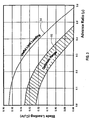
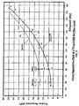
- the useful limit blade loading for a typical rotor system is given in Figure 3 by curve 14 as function of the helicopter advance ratio m, ie the ratio of the helicopter forward speed to the rotor tip rotational tip speed V T .
- m the ratio of the helicopter forward speed to the rotor tip rotational tip speed
- An optimum range 16 of blade loading can also be derived through flight test for a specific helicopter rotor system as a function of advance ratio as shown in Figure 3. For a given advance ratio, the optimum blade loading range is defmed by the blade loadings required to optimize the various flight performance parameters such as endurance, range and climb rate.
- the OSR of the present invention allows for the adjustment to the rotor RPM to maintain a blade loading within the optimum range. By operating below 100% of RPM, the power required to drive the rotor at the decreased RPM is also decreased.
- the adjustment to rotor RPM and power can be accomplished manually or automatically as for example by computer.
- the pilot will manually adjust the rotor RPM and engine power to minimize fuel consumption (either directly measured or by observing an indication of engine power).
- the pilot will adjust RPM and airspeed for maximizing the miles travelled per unit of fuel. In climb at a given power setting, the pilot will adjust the rotor RPM and airspeed for maximizing the climb rate.
- An automated OSR will operate the same way.
- Information such as fuels consumptions and miles travelled per unit of fuel consumed will be monitor by the computer.
- the pilot will select the flight performance parameter that needs to be optimized, eg range, endurance, rate of climb, etc and the computer will adjust the rotor RPM, power and airspeed settings accordingly for maximizing the selected performance.
- the optimum blade loading range as a function of advance ratio is predetermined from flight testing and stored on the computer which in turn will adjust the rotor RPM and power setting so as to maintain the blade loading within the predetermined range for any pilot controlled airspeed and rate of climb.
- the OSR In order to be able to operate over a wide RPM range, the OSR is designed specifically to be able to operate close to or on rotor excitation frequencies.
- the OSR is capable of operating a long time under full rotor lift load at or near such frequencies.
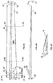
- the OSR rotor blades are designed to be very stiff and lightweight. By increasing the stiffness of the blades in flap in relation to the feathering axis 30 ( Figure 4A), the blade is better able to operate at or near the rotor excitation frequencies.
- Lag stiffness tends to be less sensitive to the excitation frequencies but if kept at a ratio to flap stiffness of an average greater than 2 it helps reduce oscillatory lag loads and helicopter vibration levels.
- the OSR rotor blades should be substantially stiffer and lighter than conventional rotor blades.
- the OSR blades require a flap stiffness and a blade weight as follows:
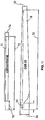
- the exemplary OSR blade of the present invention shown in Figures 4A, 4B and 4C has a length 32 including the shank 33 of about 5.44 m (17.84 feet), a maximum width 34 of about 0.46 m (18 inches) and a minimum width 36 at its tip of about 0.23 m (9 inches) (Figure 4A).
- the blade has a shank length 40 of about 35.5 cm (14 inches) and a shank diameter 42 of about 9.5 cm (3.75 inches).
- the exemplary blade has the dimensions, stiffness and weights per unit length depicted in Table I shown below.
- the exemplary blade has a continuously reducing flap and lag stiffness from the hub centre to the blade tip.
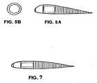
- the blade cross-section s at the blade 20% station 5C-5C, and the 70% station 5D-5D, are depicted in Figures 5A and 7, respectively.
- the 20% and 70% stations are at 20% and 70% of the rotor radius, respectively, as measured from the centre of rotor rotation.
- the cross-section of the blade shank is depicted in Figure 5B.
- the blade is constructed of a carbon-epoxy spar/shank and a carbon epoxy leading edge.
- the trailing edge is a lightweight section made in thin carbon-epoxy top and bottom skins and a full-depth honeycomb core.
- the blades can be mounted in any type or rotor hub such as hingeless, teetering or articulated, to form the rotor system.
- the blades are mounted in a hingeless rotor system.
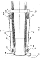
- a hingeless rotor is well known in the art. It consists of sleeves 59 for mounting the blades 18. The sleeves are fixed relative to the hub mast 61. When mounted on the hingeless rotor hub 60, the blades cannot pivot in the flap and lag directions relative to the hub ( Figure 6).
- the preferred embodiment hingeless rotor is made of steel.
- the rotor hub structure is chose to have a hub stiffness in flap and lag matched to the blade corresponding stiffness at the blade root.
- the bearing system 62 includes an inboard roller bearing 62A and an outboard needle roller bearing 62B is incorporated for blade pitch changes about the feathering axis is also required to resist moments that are substantially greater than those for an articulated rotor system.
- a needle thrust bearing 64 is located between the bearing 62A and a capture split pin 65.
- a circular section blade root spar 66 located inside a hub structure 59 lies between a bonded titanium inner sleeve 68 and a titanium blade receiving sleeve 69. The blade 18 is held by a blade quick release pin 79.
- a grease seal 67 is located adjacent the bearing 62B.
- the compared conventional blade 70 has a length 72 of about 4.01 m (13.17 feet), a constant width 74 of about 17.1 cm (6.75 inches) and a shank length 76 of about 48.3 cm (19 inches).
- the OSR blades are 85 fold stiffer at about 10% radius than the conventional articulated rotor blades which are hinged at the root in the flap direction (up-down) and lag direction (forward-aft in the plane of the rotor).
- the conventional blades must be heavy enough in order to achieve adequate centrifugal forces to avoid excessive upward bending ("coning angle"). In spite of its 85 fold increase in stiffness, the OSR blades weight per blade surface area is less than half that of the conventional blade.
- a rotor system of the present invention can operate from 0 to 100% RPM under full lift load without reducing the rotor structural integrity. Moreover, the vibration levels produced by the rotor of the present invention are within acceptable levels as related to crew fatigue, passenger comfort and payload performance. The rotor systems of the present invention are able to avoid the structural stability, loads and vibration problems associated with the operation of the rotor over a wide range of RPM.
- the exemplary embodiment OSR blades mounted on a hingeless rotor forming an exemplary OSR were analyzed, optimized and its performance verified using 9 integrated dynamics analysis tools for Computational Fluid Dynamics, structure, structural dynamics and control dynamics.
- the most important of these tools is CAMRAD II (originated by Wayne Johnson and available Analytical Methods Inc, Redmond, WA) which was used extensively for evaluating rotor stability, loads, vibrations, performance and control, including Higher Harmonics Control. All performance and structural dynamic data presented are results of CAMRAD II runs with non-uniform inflow.
- the exemplary OSR exhibited no rotor dynamics instability anywhere in the design RPM range.
- Figures 8 to 10 depict power requirements when operating the OSR of the exemplary embodiment consisting of 3 blades and a hingeless hub, using a low drag unmanned helicopter fuselage, at various RPM values for improved efficiency (curve 50) and when operating the same rotor at a constant angular velocity of 380 RPM (curve 52), at a helicopter weight of 635 Kg (1400 lbs), 1179 Kg (2600 lbs) and 1814 Kg (4000 lbs), respectively at sea level.
- Figures 8 to 10 were created from data obtained from the CAMRAD II analyses.
- Figure 9 shows the performance gains at an average weight of 1179 Kg (2600 lbs).
- the 45% reduction in required power and fuel consumption at a loiter speed of about 111 Km/h (60 knots) will provide an 82% increase in maximum endurance for the same total fuel capacity.
- the 38% reduction in power required at 148 Km/h (80 knots) should provide a 61 % increase in maximum range.
- Figure 10 shows that even at an overload weight of 1814 Kg (4000 lbs), the reduction in power of about 25% required at 120 to 148 Km/h (65 to 80 knots) and the increase in speed at a constant power level are substantial.
- OSR hover Out of Ground Effect
- the OSR can be made to operated at 2 or more angular velocities.
- the benefit in efficiency will be substantial but not as great as the benefits achieved by using an OSR that operates over a wide range of RPM.
Landscapes
- Engineering & Computer Science (AREA)
- Mechanical Engineering (AREA)
- Aviation & Aerospace Engineering (AREA)
- Physics & Mathematics (AREA)
- Fluid Mechanics (AREA)
- Toys (AREA)
Claims (23)
- Procédé permettant d'améliorer l'efficacité d'un hélicoptère pour un état de vol spécifique, l'hélicoptère comprenant un rotor ayant des pales (18) s'étendant radialement, et un moteur délivrant de l'énergie pour faire tourner le rotor, ledit procédé comprenant les étapes consistant à :déterminer une charge de pale du rotor (14, 16) pour obtenir une efficacité améliorée dans l'état de vol, dans lequel ladite charge de pale du rotor dépend du nombre de tours par minute (NTM) ;établir une valeur de NTM pour atteindre la charge de pale déterminée ; etajuster le NTM du rotor au niveau du NTM défini.
- Procédé selon la revendication 1, caractérisé en ce que l'étape de détermination comprend l'étape de détermination d'une plage de charges de pale (14, 16) pour obtenir une efficacité améliorée dans l'état de vol, et dans lequel l'étape de définition comprend l'étape de définition d'une plage de NTM pour atteindre une charge de pale à l'intérieur de la plage déterminée de charges de pale.
- Procédé selon la revendication 1 ou la revendication 2, caractérisé en ce que l'étape d'ajustement comprend l'étape d'ajustement du NTM du rotor dans une plage de 40 % à 100 % du NTM maximal du rotor.
- Procédé selon l'une quelconque des revendications précédentes, caractérisé par l'étape consistant à doter l'hélicoptère d'un rotor qui est un rotor rigide (55).
- Procédé selon l'une quelconque des revendications précédentes, caractérisé par l'étape consistant à doter l'hélicoptère d'un rotor dans lequel chaque pale comporte une emplanture (20) et une pointe (22), et dans lequel les rigidités de la pale en torsion, en décalage et en battement diminuent continûment de l'emplanture (20) de la pale à la pointe (22) de la pale.
- Procédé selon l'une quelconque des revendications précédentes, caractérisé par l'étape consistant à doter l'hélicoptère d'une pale de rotor (18) ayant une emplanture (20) et une pointe (22), et dans lequel le poids par unité de longueur de chaque pale diminue continûment de l'emplanture (20) de la pale à la pointe (22) de la pale.
- Procédé selon l'une quelconque des revendications précédentes, caractérisé par l'étape consistant à doter l'hélicoptère d'un rotor dans lequel le rotor a un rayon mesuré à partir d'un centre de rotation du rotor et un diamètre, et dans lequel les pales ont une rigidité en battement, et dans lequel, à 10 % du rayon du rotor, la rigidité en battement de la pale en livres-pouce2 est supérieure ou égale à 25 fois le diamètre du rotor en pieds à la puissance quatre.
- Procédé selon l'une quelconque des revendications précédentes, caractérisé par l'étape consistant à doter l'hélicoptère d'un rotor ayant un rayon mesuré à partir d'un centre de rotation du rotor et un diamètre, et dans lequel, à 30 % du rayon du rotor, la rigidité en battement de la pale en livres-pouce2 est supérieure ou égale à 10 fois le diamètre du rotor en pieds à la puissance quatre.
- Procédé selon l'une quelconque des revendications précédentes, caractérisé par l'étape consistant à doter l'hélicoptère d'un rotor ayant un diamètre, et dans lequel le poids total de chaque pale en livres ne dépasse pas 0,0015 fois le diamètre du rotor en pieds au cube.
- Procédé permettant d'améliorer les performances d'un hélicoptère pendant un état de vol en réduisant la consommation de carburant, l'hélicoptère comprenant un rotor fonctionnant dans une plage de nombres de tours par minute (NTM), le procédé comprenant les étapes consistant à :fournir un rotor entraîné pour tourner par une installation motrice consommant du carburant ;actionner le rotor pour obtenir la portance ;surveiller la consommation de carburant ; etfaire varier le NTM à tout niveau requis pour réduire la consommation de carburant par l'installation motrice dans l'état de vol, tout en fournissant une portance suffisante pour l'état de vol.
- Procédé selon la revendication 10, caractérisé en ce que l'étape de fourniture comprend l'étape consistant à fournir un rotor rigide (55).
- Procédé selon la revendication 10 ou la revendication 11, caractérisé en ce que l'étape de variation comprend en outre l'étape consistant à faire varier la puissance débitée de l'installation motrice.
- Procédé selon l'une quelconque des revendications 10 à 12, caractérisé en ce que l'étape de variation comprend le fait de faire varier le NTM du rotor à l'un quelconque d'au moins trois niveaux de NTM afin de réduire la consommation de carburant par l'installation motrice.
- Procédé selon l'une quelconque des revendications 10 à 13, caractérisé en ce que l'étape de fourniture comprend la fourniture d'un rotor incluant des pales (18) ayant une emplanture (20) et une pointe (22), et dans lequel les rigidités de la pale en torsion, en décalage et en battement diminuent continûment des emplantures (20) de pale aux pointes (22) de pale.
- Procédé selon l'une quelconque des revendications 10 à 14, caractérisé en ce que l'étape de fourniture comprend la fourniture d'un rotor incluant des pales (18) ayant chacune une emplanture (20) et une pointe (22), et dans lequel le poids par unité de longueur de chaque pale diminue continûment de l'emplanture (20) de la pale à la pointe (22) de la pale.
- Procédé selon l'une quelconque des revendications 10 à 15, caractérisé en ce que l'étape de fourniture comprend la fourniture d'un rotor incluant des pales (18) s'étendant radialement, dans lequel le rotor a un rayon mesuré à partir d'un centre de rotation du rotor et un diamètre, et dans lequel les pales ont une rigidité en battement, et dans lequel, à 10 % du rayon du rotor, la rigidité en battement de la pale en livres-pouce2 est supérieure ou égale à 25 fois le diamètre du rotor en pieds à la puissance quatre.
- Procédé selon l'une quelconque des revendications 10 à 16, caractérisé en ce que l'étape de fourniture comprend la fourniture d'un rotor incluant des pales s'étendant radialement, dans lequel le rotor a un rayon mesuré à partir d'un centre de rotation et un diamètre, et dans lequel les pales ont une rigidité en battement, et dans lequel, à 30 % du rayon du rotor, la rigidité en battement de la pale en livres-pouce2 est supérieure ou égale à 10 fois le diamètre du rotor en pieds à la puissance quatre.
- Procédé selon l'une quelconque des revendications 10 à 17, caractérisé en ce que le procédé de fourniture comprend le fait de fournir un rotor ayant des pales s'étendant radialement et un diamètre, et dans lequel le poids total de chaque pale en livres ne dépasse pas 0,0015 fois le diamètre du rotor en pieds au cube.
- Procédé selon l'une quelconque des revendications 10 à 18, caractérisé en ce que l'étape de variation comprend le fait de faire varier le NTM du rotor à tout niveau se situant dans la plage de 40 % à 100 % du NTM maximum du rotor.
- Procédé selon la revendication 19, caractérisé par l'étape consistant à doter l'hélicoptère d'un rotor qui est un rotor rigide (55).
- Rotor à vitesse variable pour conférer portance et poussée à un hélicoptère, ledit rotor ayant un rayon mesuré à partir d'un centre de rotation du rotor et un diamètre, et comprenant :un moyeu de rotor (60) ; et au moins deux pales (18) couplées radialement au moyeu, chaque pale ayant une emplanture (20) proximale par rapport au moyeu (60), et une pointe (22) distale par rapport au moyeu (60),caractérisé en ce que le poids de chaque pale en livres ne dépasse pas le produit de 0,0015 fois le diamètre du rotor en pieds au cube, et dans lequel la rigidité en battement de chaque pale (18) en livres-pouce2, à 10 % du rayon du rotor, est supérieure ou égale au produit de 25 fois ledit diamètre du rotor en pieds à la puissance quatre ou, à 30 % du rayon du rotor, est supérieure ou égale au produit de 10 fois ledit diamètre du rotor en pieds à la puissance quatre.
- Rotor selon la revendication 21, caractérisé en ce que le poids de chaque pale par unité de longueur diminue continûment de l'emplanture de la pale à la pointe de la pale.
- Rotor selon la revendication 21 ou la revendication 22, caractérisé en ce que les rigidités en torsion, en décalage et en battement de chaque pale (18) diminuent continûment de l'emplanture (20) de la pale à la pointe (22) de la pale.
Applications Claiming Priority (3)
| Application Number | Priority Date | Filing Date | Title |
|---|---|---|---|
| US7550998P | 1998-02-20 | 1998-02-20 | |
| US75509P | 1998-02-20 | ||
| PCT/US1999/003627 WO1999042360A1 (fr) | 1998-02-20 | 1999-02-19 | Rotor a vitesse optimale |
Publications (3)
| Publication Number | Publication Date |
|---|---|
| EP1056640A1 EP1056640A1 (fr) | 2000-12-06 |
| EP1056640A4 EP1056640A4 (fr) | 2001-04-04 |
| EP1056640B1 true EP1056640B1 (fr) | 2006-04-26 |
Family
ID=22126232
Family Applications (1)
| Application Number | Title | Priority Date | Filing Date |
|---|---|---|---|
| EP99934271A Expired - Lifetime EP1056640B1 (fr) | 1998-02-20 | 1999-02-19 | Rotor a vitesse optimale |
Country Status (6)
| Country | Link |
|---|---|
| US (2) | US6007298A (fr) |
| EP (1) | EP1056640B1 (fr) |
| JP (1) | JP4358435B2 (fr) |
| AU (1) | AU3303299A (fr) |
| DE (1) | DE69931035T2 (fr) |
| WO (1) | WO1999042360A1 (fr) |
Families Citing this family (28)
| Publication number | Priority date | Publication date | Assignee | Title |
|---|---|---|---|---|
| US6641365B2 (en) * | 1998-02-20 | 2003-11-04 | Abraham E. Karem | Optimum speed tilt rotor |
| US6953554B2 (en) | 1999-12-23 | 2005-10-11 | Dow Global Technologies Inc. | Catalytic devices and method of making said devices |
| US8372139B2 (en) * | 2001-02-14 | 2013-02-12 | Advanced Bio Prosthetic Surfaces, Ltd. | In vivo sensor and method of making same |
| US6671590B1 (en) * | 2001-04-30 | 2003-12-30 | The United States Of America As Represented By The Administrator Of The National Aeronautics And Space Administration | Method and system for active noise control of tiltrotor aircraft |
| DE10141098A1 (de) * | 2001-08-22 | 2003-03-06 | Gen Electric | Windkraftanlage |
| FR2878288B1 (fr) * | 2004-11-25 | 2007-01-19 | Eurocopter France | Procede et dispositif pour optimiser l'enveloppe de performances d'un turbomoteur |
| US8864062B2 (en) | 2005-08-15 | 2014-10-21 | Abe Karem | Aircraft with integrated lift and propulsion system |
| US7438259B1 (en) * | 2006-08-16 | 2008-10-21 | Piasecki Aircraft Corporation | Compound aircraft control system and method |
| JP4240112B2 (ja) * | 2006-11-13 | 2009-03-18 | トヨタ自動車株式会社 | 垂直離着陸機 |
| WO2009111568A1 (fr) * | 2008-03-04 | 2009-09-11 | Karem Aircraft, Inc. | Structure de racine de pale composite |
| EP2274203A4 (fr) * | 2008-04-23 | 2014-10-15 | Abe Karem | Systèmes de moyeu de rotor et procédés associés |
| US8561938B2 (en) | 2010-05-31 | 2013-10-22 | Executive Access Inc. | Directional control for a helicopter |
| WO2012109126A1 (fr) | 2011-02-08 | 2012-08-16 | Dow Global Technologies Llc | Système et procédé de réduction des émissions issues d'un procédé de combustion |
| FR3000465B1 (fr) | 2012-12-27 | 2015-02-13 | Eurocopter France | Procede d'entrainement en rotation d'un rotor principal de giravion, selon une consigne de vitesse de rotation a valeur variable |
| DE102015121502B4 (de) * | 2015-12-10 | 2025-02-13 | Tensor AG | Tragschrauberrotorblatt zur autorotatorischen Auftriebserzeugung |
| US10569870B2 (en) | 2016-11-18 | 2020-02-25 | Textron Innovations Inc. | Proprotor systems for tiltrotor aircraft |
| US20180162526A1 (en) * | 2016-12-12 | 2018-06-14 | Bell Helicopter Textron Inc. | Proprotor Systems for Tiltrotor Aircraft |
| US10232932B2 (en) | 2017-03-22 | 2019-03-19 | Bell Helicopter Textron Inc. | High stiffness hub assembly for proprotor systems |
| JP6955280B2 (ja) | 2017-05-22 | 2021-10-27 | オーバーエアー インコーポレイテッドOverair,Inc. | 電動vtol航空機 |
| US10974826B2 (en) | 2017-05-22 | 2021-04-13 | Overair, Inc. | EVTOL having many variable speed tilt rotors |
| US10472059B2 (en) | 2017-07-13 | 2019-11-12 | Bell Textron Inc. | Inboard bearing assemblies for proprotor systems |
| US10486807B2 (en) | 2017-07-13 | 2019-11-26 | Bell Textron Inc. | Inboard bearing assemblies having independent shoes |
| US10479497B2 (en) | 2017-07-13 | 2019-11-19 | Bell Textron Inc. | Inboard bearing assemblies having load transfer shoe bolts |
| US10514060B2 (en) | 2017-07-13 | 2019-12-24 | Textron Innovations Inc. | Inboard bearing assemblies with anti-rotation features |
| US10507912B2 (en) | 2017-07-13 | 2019-12-17 | Bell Textron Inc. | Inboard bearing assemblies with improved accessibility |
| US10494091B2 (en) | 2017-07-13 | 2019-12-03 | Bell Textron Inc. | Hub bolt supported inboard bearing assemblies |
| US11027834B2 (en) | 2018-02-22 | 2021-06-08 | Textron Innovations Inc. | Inboard centrifugal force bearing attachment |
| US11760473B2 (en) | 2021-02-11 | 2023-09-19 | Karem Aircraft, Inc. | Rotorcraft with interchangeable rotor diameters |
Family Cites Families (8)
| Publication number | Priority date | Publication date | Assignee | Title |
|---|---|---|---|---|
| US3713751A (en) * | 1970-10-29 | 1973-01-30 | United Aircraft Corp | Aerodynamic blade with high stiffness-to-weight ratio |
| US3960348A (en) * | 1975-08-04 | 1976-06-01 | United Technologies Corporation | Aerodynamic surface control feel augmentation system |
| US4115755A (en) * | 1976-06-11 | 1978-09-19 | United Technologies Corporation | Aerodynamic surface load sensing |
| EP0037633B1 (fr) * | 1980-03-28 | 1986-07-30 | WESTLAND plc | Pale de rotor pour hélicoptère |
| US4632337A (en) * | 1981-09-21 | 1986-12-30 | Hughes Helicopters, Inc. | Helicopter rotor transmission systems |
| US4601639A (en) * | 1984-03-19 | 1986-07-22 | Bell Helicopter Textron Inc. | Nodalized rotor |
| GB8625712D0 (en) * | 1986-10-28 | 1987-03-18 | Westland Plc | Transmission system |
| JP3029981B2 (ja) * | 1995-04-27 | 2000-04-10 | 株式会社コミュータヘリコプタ先進技術研究所 | ヘリコプタの動力伝達装置 |
-
1999
- 1999-02-19 AU AU33032/99A patent/AU3303299A/en not_active Abandoned
- 1999-02-19 WO PCT/US1999/003627 patent/WO1999042360A1/fr not_active Ceased
- 1999-02-19 US US09/253,391 patent/US6007298A/en not_active Expired - Lifetime
- 1999-02-19 JP JP2000532331A patent/JP4358435B2/ja not_active Expired - Lifetime
- 1999-02-19 EP EP99934271A patent/EP1056640B1/fr not_active Expired - Lifetime
- 1999-02-19 DE DE69931035T patent/DE69931035T2/de not_active Expired - Lifetime
-
2000
- 2000-12-05 US US09/731,150 patent/US20010001033A1/en not_active Abandoned
Also Published As
| Publication number | Publication date |
|---|---|
| EP1056640A1 (fr) | 2000-12-06 |
| DE69931035T2 (de) | 2007-05-10 |
| US6007298A (en) | 1999-12-28 |
| EP1056640A4 (fr) | 2001-04-04 |
| US20010001033A1 (en) | 2001-05-10 |
| AU3303299A (en) | 1999-09-06 |
| WO1999042360A1 (fr) | 1999-08-26 |
| DE69931035D1 (de) | 2006-06-01 |
| JP2002503593A (ja) | 2002-02-05 |
| JP4358435B2 (ja) | 2009-11-04 |
Similar Documents
| Publication | Publication Date | Title |
|---|---|---|
| EP1417125B1 (fr) | Rotor basculant a vitesse optimale | |
| US6007298A (en) | Optimum speed rotor | |
| US8066219B2 (en) | Anhedral tip blades for tiltrotor aircraft | |
| EP1585665B1 (fr) | Pale de rotor orientable a fente de bord d'attaque | |
| US20100270435A1 (en) | Wing efficiency for tilt-rotor aircraft | |
| EP3178739B1 (fr) | Répartition de la torsion de pale d'aéronef à voilure tournante à grande vitesse | |
| EP3201077B1 (fr) | Aéronef à voilure tournante et à deux rotors | |
| US4486146A (en) | Aircraft propulsion means | |
| US8864062B2 (en) | Aircraft with integrated lift and propulsion system | |
| CA2967402C (fr) | Propulsion distribuee | |
| US9120564B1 (en) | Tip jet attachment apparatus and method | |
| EP0250062A2 (fr) | Pale d'hélice | |
| EP3323720B1 (fr) | Systèmes de rotor orientable pour avion à rotors basculants | |
| WO2019083646A1 (fr) | Véhicule de vol | |
| US8128034B2 (en) | Rotorcraft with opposing roll mast moments, and related methods | |
| McVeigh et al. | Influence of tip shape, chord, blade number, and airfoil on advanced rotor performance | |
| US20050281676A1 (en) | Multi-hedral rotary wing | |
| RU2838699C1 (ru) | Беспилотный летательный аппарат | |
| CN120482350A (zh) | 一种适用于旋翼类飞行器的高效静音桨叶 | |
| WO2025132911A1 (fr) | Ensemble rotor d'aéronef et aéronef | |
| Currie | Propeller Design Consideration for Turbine Powered Aircraft |
Legal Events
| Date | Code | Title | Description |
|---|---|---|---|
| PUAI | Public reference made under article 153(3) epc to a published international application that has entered the european phase |
Free format text: ORIGINAL CODE: 0009012 |
|
| 17P | Request for examination filed |
Effective date: 20000817 |
|
| AK | Designated contracting states |
Kind code of ref document: A1 Designated state(s): DE FR GB |
|
| A4 | Supplementary search report drawn up and despatched |
Effective date: 20010216 |
|
| AK | Designated contracting states |
Kind code of ref document: A4 Designated state(s): DE FR GB |
|
| RIC1 | Information provided on ipc code assigned before grant |
Free format text: 7B 64C 27/04 A, 7B 64C 27/473 B |
|
| 17Q | First examination report despatched |
Effective date: 20040331 |
|
| GRAP | Despatch of communication of intention to grant a patent |
Free format text: ORIGINAL CODE: EPIDOSNIGR1 |
|
| GRAS | Grant fee paid |
Free format text: ORIGINAL CODE: EPIDOSNIGR3 |
|
| GRAA | (expected) grant |
Free format text: ORIGINAL CODE: 0009210 |
|
| AK | Designated contracting states |
Kind code of ref document: B1 Designated state(s): DE FR GB |
|
| REG | Reference to a national code |
Ref country code: GB Ref legal event code: FG4D |
|
| REF | Corresponds to: |
Ref document number: 69931035 Country of ref document: DE Date of ref document: 20060601 Kind code of ref document: P |
|
| ET | Fr: translation filed | ||
| PLBE | No opposition filed within time limit |
Free format text: ORIGINAL CODE: 0009261 |
|
| STAA | Information on the status of an ep patent application or granted ep patent |
Free format text: STATUS: NO OPPOSITION FILED WITHIN TIME LIMIT |
|
| 26N | No opposition filed |
Effective date: 20070129 |
|
| REG | Reference to a national code |
Ref country code: FR Ref legal event code: PLFP Year of fee payment: 18 |
|
| REG | Reference to a national code |
Ref country code: FR Ref legal event code: PLFP Year of fee payment: 19 |
|
| REG | Reference to a national code |
Ref country code: FR Ref legal event code: PLFP Year of fee payment: 20 |
|
| PGFP | Annual fee paid to national office [announced via postgrant information from national office to epo] |
Ref country code: DE Payment date: 20180413 Year of fee payment: 20 |
|
| PGFP | Annual fee paid to national office [announced via postgrant information from national office to epo] |
Ref country code: FR Payment date: 20180420 Year of fee payment: 20 |
|
| PGFP | Annual fee paid to national office [announced via postgrant information from national office to epo] |
Ref country code: GB Payment date: 20180406 Year of fee payment: 20 |
|
| REG | Reference to a national code |
Ref country code: DE Ref legal event code: R071 Ref document number: 69931035 Country of ref document: DE |
|
| REG | Reference to a national code |
Ref country code: GB Ref legal event code: PE20 Expiry date: 20190218 |
|
| PG25 | Lapsed in a contracting state [announced via postgrant information from national office to epo] |
Ref country code: GB Free format text: LAPSE BECAUSE OF EXPIRATION OF PROTECTION Effective date: 20190218 |