EP1056972B1 - Reflektor für kfz-äussere beleuchtung - Google Patents
Reflektor für kfz-äussere beleuchtung Download PDFInfo
- Publication number
- EP1056972B1 EP1056972B1 EP98950801A EP98950801A EP1056972B1 EP 1056972 B1 EP1056972 B1 EP 1056972B1 EP 98950801 A EP98950801 A EP 98950801A EP 98950801 A EP98950801 A EP 98950801A EP 1056972 B1 EP1056972 B1 EP 1056972B1
- Authority
- EP
- European Patent Office
- Prior art keywords
- disc
- discs
- joined
- reflector
- mini
- Prior art date
- Legal status (The legal status is an assumption and is not a legal conclusion. Google has not performed a legal analysis and makes no representation as to the accuracy of the status listed.)
- Expired - Lifetime
Links
- 229910052782 aluminium Inorganic materials 0.000 abstract description 7
- XAGFODPZIPBFFR-UHFFFAOYSA-N aluminium Chemical compound [Al] XAGFODPZIPBFFR-UHFFFAOYSA-N 0.000 abstract description 7
- 230000000712 assembly Effects 0.000 abstract description 3
- 238000000429 assembly Methods 0.000 abstract description 3
- 239000000463 material Substances 0.000 description 3
- 239000002184 metal Substances 0.000 description 3
- 229910052751 metal Inorganic materials 0.000 description 3
- 238000002347 injection Methods 0.000 description 2
- 239000007924 injection Substances 0.000 description 2
- 238000004519 manufacturing process Methods 0.000 description 2
- 239000007787 solid Substances 0.000 description 2
- 230000004075 alteration Effects 0.000 description 1
- 239000004411 aluminium Substances 0.000 description 1
- 238000000576 coating method Methods 0.000 description 1
- 230000001419 dependent effect Effects 0.000 description 1
- 230000008030 elimination Effects 0.000 description 1
- 238000003379 elimination reaction Methods 0.000 description 1
- 238000005286 illumination Methods 0.000 description 1
- 239000002991 molded plastic Substances 0.000 description 1
Images



Classifications
-
- F—MECHANICAL ENGINEERING; LIGHTING; HEATING; WEAPONS; BLASTING
- F21—LIGHTING
- F21V—FUNCTIONAL FEATURES OR DETAILS OF LIGHTING DEVICES OR SYSTEMS THEREOF; STRUCTURAL COMBINATIONS OF LIGHTING DEVICES WITH OTHER ARTICLES, NOT OTHERWISE PROVIDED FOR
- F21V7/00—Reflectors for light sources
- F21V7/10—Construction
-
- F—MECHANICAL ENGINEERING; LIGHTING; HEATING; WEAPONS; BLASTING
- F21—LIGHTING
- F21S—NON-PORTABLE LIGHTING DEVICES; SYSTEMS THEREOF; VEHICLE LIGHTING DEVICES SPECIALLY ADAPTED FOR VEHICLE EXTERIORS
- F21S43/00—Signalling devices specially adapted for vehicle exteriors, e.g. brake lamps, direction indicator lights or reversing lights
- F21S43/10—Signalling devices specially adapted for vehicle exteriors, e.g. brake lamps, direction indicator lights or reversing lights characterised by the light source
- F21S43/13—Signalling devices specially adapted for vehicle exteriors, e.g. brake lamps, direction indicator lights or reversing lights characterised by the light source characterised by the type of light source
- F21S43/14—Light emitting diodes [LED]
-
- F—MECHANICAL ENGINEERING; LIGHTING; HEATING; WEAPONS; BLASTING
- F21—LIGHTING
- F21V—FUNCTIONAL FEATURES OR DETAILS OF LIGHTING DEVICES OR SYSTEMS THEREOF; STRUCTURAL COMBINATIONS OF LIGHTING DEVICES WITH OTHER ARTICLES, NOT OTHERWISE PROVIDED FOR
- F21V7/00—Reflectors for light sources
-
- Y—GENERAL TAGGING OF NEW TECHNOLOGICAL DEVELOPMENTS; GENERAL TAGGING OF CROSS-SECTIONAL TECHNOLOGIES SPANNING OVER SEVERAL SECTIONS OF THE IPC; TECHNICAL SUBJECTS COVERED BY FORMER USPC CROSS-REFERENCE ART COLLECTIONS [XRACs] AND DIGESTS
- Y10—TECHNICAL SUBJECTS COVERED BY FORMER USPC
- Y10S—TECHNICAL SUBJECTS COVERED BY FORMER USPC CROSS-REFERENCE ART COLLECTIONS [XRACs] AND DIGESTS
- Y10S362/00—Illumination
- Y10S362/80—Light emitting diode
Definitions
- the present invention relates to reflectors and, more particularly, to a reflector for use in automotive lighting and other point light source applications.
- LEDs light emitting devices
- point light sources have the advantage of functioning for a longer time than do light bulbs, and, if a single point light source malflunctions, the illumination level of the light assembly is barely affected.
- the reflectors for point light source based-light assemblies are different from reflectors for single-bulb assemblies.
- the point light source reflectors must define a plurality of mini-reflectors-one for each of the point light sources. Usually, each of the mini-reflectors is cone-shaped or has the shape of another revolved surface. Each point light source is mounted near the apex of the mini-reflector, which directs the light away from the reflector.
- a lens (often colored) optionally covers the reflector to redirect the light.
- Known point light source reflectors are injection molded plastic vapor coated with aluminum, a commonly-used, highly reflective material.
- the injection molded reflectors are relatively expensive to produce, involving several production steps and including the vapor coating process.
- the reflectors have limited acceptance due to cost constraints.
- FR-A-2562301 relates to a luminous panel including a light source associated with each of a plurality of mini-reflectors (70); a lens; and a light reflector comprising a full revolved surface.
- a point light source reflector which includes a pair of nested plates, each providing a portion of each mini-reflector cone or other revolved surface.
- the nested plates together provide a complete mini-reflector cone for each light source.
- each plate is a metal stamping, such as anodized aluminum or other specular metal or other material.
- the reflector is less expensive than the prior art reflector, due to the elimination of expensive production steps.
- the aluminium plates are stamped such that each plate has a plurality of stamped segments attached to the plate by a joint. Each segment is formed into a half-cone or other partial revolved surface extending away from the plate. The half-cone remains attached to the plate at the joint.
- the arrangement of holes with the half-cones extending therefrom allows the plates to be identical to one another and to be nested so that the half-cones of one plate interfit with the other half cones of the other plate.
- the first plate is rotated 180° relative to the second plate and is nested with the second plate to form a joined disc.
- the cone portions of the second plate slip through the semi-circular holes in the first plate and meet the cone portions of the first plate.
- the cone portions mesh and form full cones extending from the joined plate.
- the plate assembly is unapertured except for the cones.
- the present invention is described in connection with automotive exterior lighting. However, the invention is equally well suited as a reflector in other LED or point light source applications.
- a lighting assembly incorporating the reflector of the present invention is illustrated in the drawings and generally designated 5.
- the assembly includes a reflector 43, a plurality of LEDs 150 or other point light source, and an optional lens 158. Both the LEDs 150 and the reflector 43 are conventional and well known to those skilled in the art.
- the novelty of the present invention resides in the reflector 43, which is a sandwich of two identical, nested discs 62.
- the nested discs 62 provide a plurality of cone-shaped or other revolved surface mini-reflectors 70, each supporting one of the LEDs 150.
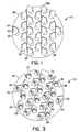
- a plate or disc according to a preferred embodiment of this invention is illustrated in Figs. 1 and 2 and generally designated 10.
- the disc is illustrated as a circular shape; however, the concept of the invention is not limited by the shape of the disc.
- the preferred shape of the disc will depend on the particular application.
- the disc is formed of anodized aluminum, which provides the desired reflective and structural properties at a relatively low cost. Any other specular metal or material may be used depending on the particular application.
- the aluminum disc 10 is stamped to form a plurality of semi-circular holes 20.
- segments 22 of the disc 10 are defined by stamping the perimeter 24 of the segments 22.
- Each segment 22 is attached to the disc 10 by a joint 26, i.e. a portion 28 of the segment perimeter 24 which is not stamped.
- the segments 22 may extend beyond the perimeter 30 of the disc 10 due to the layout of the semi-circular holes 20 and segments 22 as seen in segment 22a.
- each segment 22 is bent at its joint 26 and rolled so that it forms a protrusion lying outside the plane of the disc 10.
- the removal of the segments 22 from the disc 10 form a plurality of second holes 32 on the disc 10.
- Each segment 22 is formed into a half (or partial) cone shape 34 or mini-reflector portion, with an open top 42 and an apex 37, and remains attached to the disc 10 at the joint 26.
- the mini reflector portion is not limited to a half-cone shape. It may have the shape of any partially revolved surface, such as a parabola or ellipse.
- the perimeter 36 of each half cone 34 meets the perimeter 38 of a semi-circular hole 20, and these perimeters 36 and 38 define a circular hole 40.
- the segment 22 may be formed into shapes other than a half-cone, depending on the design of the segment 20.
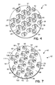
- a reflector As seen in Fig. 6, two of these discs 10, each having a front side 77 and 76 and a back side 74 and 75, are nested to form a reflector, generally designated 43.
- a first disc 50 is rotated 180° so that the top 52 of the first disc 50 meets the bottom 54 of a second disc 56.
- the stamped design on the top portion 58 and 59 of each disc 50 and 56 is a reversed image of the design on the bottom portion 60 and 61 of each disc 50 and 56. Therefore, when the first disc 50 is rotated 180°, it meshes with the second disc 56, forming a joined disc 62.
- the half cones 64 of the second disc 56 pass through the semi-circular holes 66 of the first disc 50 and mesh with the half cones 68 of the first disc 50; the half cones 64 and 68 form a fill cone 70 or mini-reflector having an open top 72.
- the back side 74 of the first disc 50 meets the front side 76 of the second disc 56.
- the semi-circular holes 66 and 80 on the first and second discs 50 and 56 meet and form a circular hole 82 in the joined disc 62.
- Each circular hole 82 is encircled at its perimeter 84 by a full cone 70.
- the second holes 86 and 88 on each disc 50 and 56, formed by the removal of the segments 90 and 92, are not readily apparent on the joined disc 62.
- the second holes 86 on the first disc 50 are met by solid portions 100 of the front side 76 of the second disc 56
- the second holes 88 on the second disc 56 are met by solid portions 104 of the back side 74 of the first disc 50.
- the joined disc 62 appears to contain only the circular holes 82 encircled by the full cones 70.
- the areas 108 and 110 on the joined disc 62 which formed the second holes 86 and 88 on the first and second discs 50 and 56 may be identified by examination of the joined disc 62.
- the joined disc 62 is obviously two nested discs 50 and 56, and even though the second hole areas 108 and 110 are covered, they form distinct regions 112 on the front and back sides 114 and 116 of the joined disc 62.
- LEDs 150 or other point light source are mounted on a circuit board 151.
- the reflector 43 is placed over the circuit board 151 and on top of the LEDs 150.
- the reflector 43 is positioned such that the LEDs 150 lie within the open top 72 of each cone 70 and are directed towards the open base 152 of the cone 70.
- a lens 158 optionally covers the joined disc 62 and redirects the light from the plurality of LEDs 150.
- a third disc 200 may be sandwiched on top of the nested disc 62. This may be desirable in applications requiring a smooth surface facing the reflector 43.
- the third aluminum disc 200 is placed over the back side 116 of the joined disc 62; thus the distinct regions 112 on the back side 116 of the joined disc 62 are hidden.
- This third disc 200 is stamped with a plurality of circular holes 210 which align with the circular holes 82 in the joined disc 62.
- the third disc 200 is placed on the back side 116 of the joined disc 62, the light from the LEDs 150 passes through both the circular holes 82 in the joined disc 62 and the circular holes 210 in the third disc 200 and towards the lens 158.
- Providing a smooth surface on the joined disc 62 may be most desirable when a clear lens is used
Landscapes
- Engineering & Computer Science (AREA)
- General Engineering & Computer Science (AREA)
- Physics & Mathematics (AREA)
- Microelectronics & Electronic Packaging (AREA)
- Optics & Photonics (AREA)
- Non-Portable Lighting Devices Or Systems Thereof (AREA)
Claims (10)
- Beleuchtungsvorrichtung (5) mit: einer Lichtquelle (150), die mit jedem von mehreren Mini-Reflektoren (70) verbunden ist; und einer Linse (158) dadurch gekennzeichnet, daß die Vorrichtung aufweist:einen Reflektor (43), der erste (50) und zweite (56) Platten aufweist, wobei jede Platte eine Vorderseite (77, 76) und eine Rückseite (74, 75) aufweist, jede Platte weiterhin mehrere Mini-Reflektor-Teile aufweist, von denen jedes mit einem von mehreren Lochbereichen (20) verbunden ist, wobei die Mini-Reflektor-Teile sich von den Rückseiten der Platten erstrecken, die ersten und zweiten Platten ineinander gesetzt sind mit der Rückseite (74) der ersten Platte gegen die Vorderseite (76) der zweiten Platte, jedes der Mini-Reflektor-Teile (64) der ersten Platte mit einem der Mini-Reflektor-Teile (68) der zweiten Platte zusammenwirkt, um die Mini-Reflektoren (70) zu bilden, und wobei die Linse (158) die Vorderseite der ersten Platte abdeckt.
- Vorrichtung nach Anspruch 1, bei dem jeder der Mini-Reflektor-Teile, die sich von den ersten oder zweiten Platten erstrecken eine partiell umlaufende Oberfläche bilden und jeder der Mini-Reflektoren eine vollständig umlaufende Oberfläche bildet.
- Vorrichtung nach Anspruch 1, bei dem jedes der Mini-Reflektor-Teile von einem Segment (22) gebildet wird, das aus der Platte gestanzt worden ist, wobei jede der Platten eine Öffnung (20) ausbildet, die durch das Entfernen des Segments gebildet wird, und die Öffnung der ersten Platte auf die Vorderseite der zweiten Platte trifft und die Öffnung der zweiten Platte auf die Rückseite der ersten Platte trifft, wenn die erste und zweite Platte ineinander gesetzt sind.
- Vorrichtung nach Anspruch 1 mit weiterhin:einer dritten Platte (200), die über die Frontseite der ersten Platte gelegt ist, wobei die dritte Platte mehrere Öffnungen (210) definiert, jede ausgerichtet zu einem der Mini-Reflektoren.
- Lichtreflektor mit einer vollständig umlaufenden Oberfläche (70), gekennzeichnet durch erste (50) und zweite (56) Platten, von denen jede eine Öffnung definiert und eine partiell umlaufende Oberfläche aufweist, die sich von der Platte erstreckt und zu der Öffnung ausgerichtet ist, wobei die ersten und zweiten Platten ineinander gesetzt sind, wobei die Öffnungen zusammenwirken um eine gemeinsame Öffnung zu bilden, die durch die ineinander gesetzten Platten (62) definiert ist, wobei die partiell umlaufenden Oberflächen ineinandergreifen, um eine vollständig umlaufende Oberfläche zu bilden, die die gemeinsame Öffnung umgibt, wobei die ersten und zweiten Platten weiterhin zusammenwirken, um etwaige gemeinsame Öffnungen in Bereichen der ineinander gesetzten Platten zu verhindern, die nicht zu den vollständig umlaufenden Oberflächen ausgerichtet sind.
- Apparat (5) zum Reflektieren von Licht, gekennzeichnet durch erste (50) und zweite (56) Platten, wobei jede der Platten einen Vorsprung (64, 68) aufweist, der sich von der Vorderseite der Platte erstreckt, wobei die Platten ineinander gesetzt sind, um eine gemeinsame Platte (62) zu bilden, wobei die Vorsprünge ineinandergreifen um einen gemeinsamen Vorsprung (70) zu bilden, der sich von der Vorderseite der gemeinsamen Platte erstreckt.
- Apparat nach Anspruch 6, bei dem jede der Platten (50, 56) mehrere erste Öffnungen definiert, wobei die ersten Öffnungen zusammenwirken um eine gemeinsame Öffnung zu bilden, die durch die gemeinsame Platte (62) definiert ist, wobei die Vorsprünge sich von jeder der Platten erstrecken, gestanzt aus einem Segment (22) der Platten, und jede der Platten mehrere Öffnungen definiert, die durch das Entfernen der Segmente gebildet sind.
- Apparat nach Anspruch 7, bei dem die zweiten Öffnungen der ersten Platte auf die Vorderseite (76) der zweiten Platte treffen und die zweiten Öffnungen der zweiten Platte auf die Rückseite (74) der ersten Platte treffen, wenn die erste und zweite Platte ineinander gesetzt sind.
- Apparat nach Anspruch 7, bei dem jeder der sich von den ersten und zweiten Platten erstreckenden Vorsprünge (64, 68) eine partiell umlaufende Oberfläche bildet, wobei jede der partiell umlaufenden Oberflächen der ersten und zweiten Platten ineinandergreifen, um eine vollständig umlaufende Oberfläche (70) zu bilden, wenn die Platten ineinander gesetzt sind, wobei die vollständig umlaufende Oberfläche sich von der Vorderseite der gemeinsame Platte erstreckt, und die umlaufende Oberfläche die gemeinsame Öffnung umgibt, die durch die gemeinsame Platte (62)definiert ist.
- Apparat nach Anspruch 5 oder Anspruch 8, mit weiterhin:einer flachen Platte (200), die über die Frontseite der gemeinsamen Platte gelegt ist, wobei die flache Platte mehrere Öffnungen (210) definiert, jede ausgerichtet zu einer der voll umlaufenden Oberflächen (70).
Applications Claiming Priority (3)
| Application Number | Priority Date | Filing Date | Title |
|---|---|---|---|
| US26924 | 1993-03-05 | ||
| US09/026,924 US6106137A (en) | 1998-02-20 | 1998-02-20 | Reflector for automotive exterior lighting |
| PCT/US1998/020534 WO1999042759A1 (en) | 1998-02-20 | 1998-10-01 | Reflector for automotive exterior lighting |
Publications (2)
| Publication Number | Publication Date |
|---|---|
| EP1056972A1 EP1056972A1 (de) | 2000-12-06 |
| EP1056972B1 true EP1056972B1 (de) | 2002-04-03 |
Family
ID=21834584
Family Applications (1)
| Application Number | Title | Priority Date | Filing Date |
|---|---|---|---|
| EP98950801A Expired - Lifetime EP1056972B1 (de) | 1998-02-20 | 1998-10-01 | Reflektor für kfz-äussere beleuchtung |
Country Status (5)
| Country | Link |
|---|---|
| US (2) | US6106137A (de) |
| EP (1) | EP1056972B1 (de) |
| AU (1) | AU9675698A (de) |
| DE (1) | DE69804681T2 (de) |
| WO (1) | WO1999042759A1 (de) |
Families Citing this family (80)
| Publication number | Priority date | Publication date | Assignee | Title |
|---|---|---|---|---|
| US6590502B1 (en) | 1992-10-12 | 2003-07-08 | 911Ep, Inc. | Led warning signal light and movable support |
| GB2330679B (en) | 1997-10-21 | 2002-04-24 | 911 Emergency Products Inc | Warning signal light |
| US6280055B1 (en) * | 1998-09-28 | 2001-08-28 | Andy Merko | Light modifier |
| US6614359B2 (en) | 1999-04-06 | 2003-09-02 | 911 Emergency Products, Inc. | Replacement led lamp assembly and modulated power intensity for light source |
| US6462669B1 (en) | 1999-04-06 | 2002-10-08 | E. P . Survivors Llc | Replaceable LED modules |
| US6700502B1 (en) | 1999-06-08 | 2004-03-02 | 911Ep, Inc. | Strip LED light assembly for motor vehicle |
| US6705745B1 (en) | 1999-06-08 | 2004-03-16 | 911Ep, Inc. | Rotational led reflector |
| WO2000074972A1 (en) | 1999-06-08 | 2000-12-14 | 911 Emergency Products, Inc. | Led light stick assembly |
| US6367949B1 (en) | 1999-08-04 | 2002-04-09 | 911 Emergency Products, Inc. | Par 36 LED utility lamp |
| TW433551U (en) * | 1999-10-26 | 2001-05-01 | You Shang Hua | Improvement of cup base for light emitting diode chip |
| AUPQ431399A0 (en) * | 1999-11-29 | 1999-12-23 | Procter, Jeffrey Kenneth | Light emitting diode reflector |
| DE10019559A1 (de) * | 2000-04-20 | 2001-10-25 | Hella Kg Hueck & Co | Fahrzeugleuchte |
| US6920269B1 (en) * | 2000-07-14 | 2005-07-19 | The Gates Corporation | Lens |
| US7439847B2 (en) | 2002-08-23 | 2008-10-21 | John C. Pederson | Intelligent observation and identification database system |
| US8188878B2 (en) | 2000-11-15 | 2012-05-29 | Federal Law Enforcement Development Services, Inc. | LED light communication system |
| WO2002041276A2 (en) | 2000-11-15 | 2002-05-23 | Snowy Village, Inc. | Led warning light and communication system |
| TWI258329B (en) * | 2002-12-04 | 2006-07-11 | Fih Co Ltd | Method of manufacturing multihole cover |
| JP3498290B1 (ja) * | 2002-12-19 | 2004-02-16 | 俊二 岸村 | 白色led照明装置 |
| DE10303969B4 (de) * | 2003-01-31 | 2008-11-27 | Osram Opto Semiconductors Gmbh | Leuchtdiodenanordnung mit einem Leuchtdiodenträger und einer Mehrzahl von Leuchtdioden |
| TW578310B (en) * | 2003-04-02 | 2004-03-01 | Au Optronics Corp | Low temperature poly silicon thin film transistor and method of forming poly silicon layer of the same |
| US20040202006A1 (en) * | 2003-04-10 | 2004-10-14 | Shou-Wei Pien | Taillight with individually replaceable LED lamps |
| TWM247778U (en) * | 2003-04-29 | 2004-10-21 | Taiwan Bull Motor Parts Co Ltd | Light for automobile |
| US20050001562A1 (en) * | 2003-07-02 | 2005-01-06 | 911Ep, Inc. | LED compensation circuit |
| DE10358053A1 (de) * | 2003-12-05 | 2005-07-14 | Siemens Ag | Lichtsignal |
| US7281818B2 (en) * | 2003-12-11 | 2007-10-16 | Dialight Corporation | Light reflector device for light emitting diode (LED) array |
| US7086765B2 (en) * | 2004-03-25 | 2006-08-08 | Guide Corporation | LED lamp with light pipe for automotive vehicles |
| DE102004019137A1 (de) * | 2004-04-16 | 2005-11-17 | Trilux-Lenze Gmbh + Co Kg | Leuchtenfeld |
| US7414546B2 (en) * | 2004-07-08 | 2008-08-19 | Honeywell International Inc. | White anti-collision light utilizing light-emitting diode (LED) technology |
| US20060028815A1 (en) * | 2004-08-03 | 2006-02-09 | Triplex Manufacturing Company | Light assembly comprising integrated passive and active illumination sources |
| TWD110149S1 (zh) * | 2004-10-14 | 2006-04-11 | 東芝照明技術股份有限公司 | 照明用發光體 |
| TWD110150S1 (zh) * | 2004-10-14 | 2006-04-11 | 東芝照明技術股份有限公司 | 照明用發光體 |
| TWD110148S1 (zh) * | 2004-10-14 | 2006-04-11 | 東芝照明技術股份有限公司 | 照明用發光體 |
| TWD110200S1 (zh) * | 2004-10-14 | 2006-04-11 | 東芝照明技術股份有限公司 | 照明用發光體 |
| TWD110201S1 (zh) * | 2004-10-14 | 2006-04-11 | 東芝照明技術股份有限公司 | 照明用發光體 |
| TWD110202S1 (zh) * | 2004-10-14 | 2006-04-11 | 東芝照明技術股份有限公司 | 照明用發光體 |
| US7977698B2 (en) * | 2005-03-18 | 2011-07-12 | Avago Technologies Ecbu Ip (Singapore) Pte. Ltd. | System and method for surface mountable display |
| US20060221613A1 (en) * | 2005-04-05 | 2006-10-05 | Coushaine Charles M | Virtual point light source |
| US7390104B2 (en) * | 2005-05-03 | 2008-06-24 | Osram Sylvania, Inc. | Portable LED lamp |
| US20060268548A1 (en) * | 2005-05-25 | 2006-11-30 | Haoli Precision Industrial Co., Ltd. | LED lighting device with light converging effect |
| DE112007001950T5 (de) | 2006-08-21 | 2009-07-02 | Innotec Corporation, Zeeland | Elektrische Vorrichtung mit platinenloser Montageanordnung für elektrische Komponenten |
| KR100793581B1 (ko) * | 2006-08-29 | 2008-01-14 | 엘지이노텍 주식회사 | 백라이트 유닛 및 이를 이용한 디스플레이 장치 |
| US8408773B2 (en) | 2007-03-19 | 2013-04-02 | Innotec Corporation | Light for vehicles |
| US7712933B2 (en) | 2007-03-19 | 2010-05-11 | Interlum, Llc | Light for vehicles |
| US9294198B2 (en) | 2007-05-24 | 2016-03-22 | Federal Law Enforcement Development Services, Inc. | Pulsed light communication key |
| US9455783B2 (en) | 2013-05-06 | 2016-09-27 | Federal Law Enforcement Development Services, Inc. | Network security and variable pulse wave form with continuous communication |
| US11265082B2 (en) | 2007-05-24 | 2022-03-01 | Federal Law Enforcement Development Services, Inc. | LED light control assembly and system |
| US9414458B2 (en) | 2007-05-24 | 2016-08-09 | Federal Law Enforcement Development Services, Inc. | LED light control assembly and system |
| US9258864B2 (en) | 2007-05-24 | 2016-02-09 | Federal Law Enforcement Development Services, Inc. | LED light control and management system |
| US9100124B2 (en) | 2007-05-24 | 2015-08-04 | Federal Law Enforcement Development Services, Inc. | LED Light Fixture |
| WO2008148039A1 (en) | 2007-05-24 | 2008-12-04 | Federal Law Enforcement Development Services, Inc. | Led light communication system |
| USD591695S1 (en) * | 2007-07-11 | 2009-05-05 | Samsung Electro-Mechanics Co., Ltd. | Light-emitting diode module |
| MX2010004433A (es) * | 2007-10-25 | 2010-05-13 | Lsi Industries Inc | Reflector. |
| US8491148B2 (en) * | 2007-10-27 | 2013-07-23 | Osram Sylvania Inc. | Chambered waterproof lamp assembly having a transparent cover switch activator |
| EP2232592B1 (de) | 2007-12-12 | 2013-07-17 | Innotec Corporation | Verfahren zum umspritzen einer leiterplatte |
| US7815339B2 (en) | 2008-01-09 | 2010-10-19 | Innotec Corporation | Light module |
| USD634884S1 (en) * | 2008-05-26 | 2011-03-22 | Toshiba Lighting & Technology Corporation | Recessed lighting fixture |
| US7744248B2 (en) * | 2008-07-08 | 2010-06-29 | Stanley Electric Co., Ltd. | Lighting fixture |
| US20100039814A1 (en) * | 2008-08-13 | 2010-02-18 | Steve Germain | Led reflector and a lamp including the same |
| US8890773B1 (en) | 2009-04-01 | 2014-11-18 | Federal Law Enforcement Development Services, Inc. | Visible light transceiver glasses |
| US20110026249A1 (en) * | 2009-07-31 | 2011-02-03 | Jonathan Wylde | Low profile LED lighting assembly |
| USD621804S1 (en) * | 2009-08-07 | 2010-08-17 | Hon Hai Precision Industry Co., Ltd. | PCB for arranging LED lights |
| TWI428535B (zh) * | 2009-11-03 | 2014-03-01 | Quarton Inc | Condenser lighting device |
| US11274808B2 (en) | 2010-06-17 | 2022-03-15 | Rtc Industries, Inc. | LED lighting assembly and method of lighting for a merchandise display |
| US9222645B2 (en) | 2010-11-29 | 2015-12-29 | RTC Industries, Incorporated | LED lighting assembly and method of lighting for a merchandise display |
| CN102705780A (zh) * | 2010-08-30 | 2012-10-03 | 欧司朗股份有限公司 | 反射器、具有该反射器的照明装置以及反射器的制造方法 |
| US9103531B2 (en) * | 2010-10-29 | 2015-08-11 | Osram Gmbh | Lighting device with bowl-like casing |
| US8543505B2 (en) | 2011-01-14 | 2013-09-24 | Federal Law Enforcement Development Services, Inc. | Method of providing lumens and tracking of lumen consumption |
| KR200464527Y1 (ko) | 2011-03-10 | 2013-01-22 | 서원조명공업 주식회사 | 엘이디등기구용 엠보싱 반사갓 |
| US20120257386A1 (en) * | 2011-06-24 | 2012-10-11 | Xicato, Inc. | Led based illumination module with a reflective mask |
| USD700584S1 (en) * | 2011-07-06 | 2014-03-04 | Cree, Inc. | LED component |
| DE112013002944T5 (de) | 2012-06-13 | 2015-02-19 | Innotec, Corp. | Flexibler Hohllichtleiter |
| DE202012011174U1 (de) * | 2012-11-21 | 2013-01-10 | P.H. Wert-Design E.K. | Leuchte |
| DE102013201950A1 (de) * | 2013-02-06 | 2014-08-07 | Osram Gmbh | Rasterleuchte mit Reflektorzellen und Halbleiterlichtquellen |
| US9265112B2 (en) | 2013-03-13 | 2016-02-16 | Federal Law Enforcement Development Services, Inc. | LED light control and management system |
| DE202013101823U1 (de) * | 2013-04-26 | 2014-07-29 | Zumtobel Lighting Gmbh | Plattenförmiges Reflektorelement für LED-Platine |
| US20150198941A1 (en) | 2014-01-15 | 2015-07-16 | John C. Pederson | Cyber Life Electronic Networking and Commerce Operating Exchange |
| US9541255B2 (en) | 2014-05-28 | 2017-01-10 | Lsi Industries, Inc. | Luminaires and reflector modules |
| US20170046950A1 (en) | 2015-08-11 | 2017-02-16 | Federal Law Enforcement Development Services, Inc. | Function disabler device and system |
| US10006607B1 (en) * | 2016-09-20 | 2018-06-26 | Spl Industries Usa, Inc. | Modular multi-aperture reflector sheets for light distribution and control |
| US10274783B2 (en) | 2017-05-05 | 2019-04-30 | Pelka & Associates, Inc. | Direct-view LED backlight with gradient reflective layer |
Family Cites Families (18)
| Publication number | Priority date | Publication date | Assignee | Title |
|---|---|---|---|---|
| US2387804A (en) * | 1942-02-05 | 1945-10-30 | William J Miskella | Reflective panel |
| US2561022A (en) * | 1949-02-08 | 1951-07-17 | Ethel C Jones | Refreshment plate |
| US3469686A (en) * | 1967-02-08 | 1969-09-30 | Monsanto Co | Retaining trays for semiconductor wafers and the like |
| US3386608A (en) * | 1967-05-15 | 1968-06-04 | Diller Kenneth | Multiple-cell molded plastic tray |
| US4254453A (en) * | 1978-08-25 | 1981-03-03 | General Instrument Corporation | Alpha-numeric display array and method of manufacture |
| US4245280A (en) * | 1979-09-04 | 1981-01-13 | Gte Products Corporation | Multilamp photoflash unit construction |
| US4399490A (en) * | 1981-02-27 | 1983-08-16 | Gte Products Corporation | Opaque reflector for multilamp photoflash array |
| JPS5896785A (ja) * | 1981-12-04 | 1983-06-08 | Stanley Electric Co Ltd | 発光ダイオ−ドの合成樹脂レンズ成形方法 |
| SE8200913L (sv) * | 1982-02-16 | 1983-08-17 | Integrerad Teknik Igt Hb | Anordning vid lysdioder |
| JPS59152147A (ja) * | 1983-02-18 | 1984-08-30 | ザ・コカ−コ−ラ・カンパニ− | 缶を取外し自在に組立てるためのアダプタ− |
| FR2562301A1 (fr) * | 1984-03-27 | 1985-10-04 | Sayag Electronic | Panneau lumineux a reseau de sources lumineuses ponctuelles |
| FR2563929B3 (fr) * | 1984-05-04 | 1986-09-12 | Thery Hindrick Sa | Panneau avertisseur lumineux |
| FR2574616B1 (fr) * | 1984-12-07 | 1987-01-23 | Radiotechnique Compelec | Matrice d'element electro-luminescents et son procede de fabrication |
| US5040681A (en) * | 1987-02-26 | 1991-08-20 | Dart Industries Inc. | Desk organizer or the like |
| FR2613858B1 (fr) * | 1987-04-09 | 1994-04-01 | Garbarini Sa A | Element de feu de signalisation de circulation routiere |
| US5404282A (en) * | 1993-09-17 | 1995-04-04 | Hewlett-Packard Company | Multiple light emitting diode module |
| US5410453A (en) * | 1993-12-01 | 1995-04-25 | General Signal Corporation | Lighting device used in an exit sign |
| US5660461A (en) * | 1994-12-08 | 1997-08-26 | Quantum Devices, Inc. | Arrays of optoelectronic devices and method of making same |
-
1998
- 1998-02-20 US US09/026,924 patent/US6106137A/en not_active Expired - Fee Related
- 1998-10-01 EP EP98950801A patent/EP1056972B1/de not_active Expired - Lifetime
- 1998-10-01 AU AU96756/98A patent/AU9675698A/en not_active Abandoned
- 1998-10-01 WO PCT/US1998/020534 patent/WO1999042759A1/en not_active Ceased
- 1998-10-01 DE DE69804681T patent/DE69804681T2/de not_active Expired - Fee Related
-
1999
- 1999-11-30 US US09/451,644 patent/US6113247A/en not_active Expired - Fee Related
Also Published As
| Publication number | Publication date |
|---|---|
| WO1999042759A1 (en) | 1999-08-26 |
| EP1056972A1 (de) | 2000-12-06 |
| US6106137A (en) | 2000-08-22 |
| DE69804681D1 (de) | 2002-05-08 |
| DE69804681T2 (de) | 2002-10-17 |
| US6113247A (en) | 2000-09-05 |
| AU9675698A (en) | 1999-09-06 |
Similar Documents
| Publication | Publication Date | Title |
|---|---|---|
| EP1056972B1 (de) | Reflektor für kfz-äussere beleuchtung | |
| US5988829A (en) | Direct/indirect lighting fixtures | |
| US5816694A (en) | Square distribution reflector | |
| US6382803B1 (en) | Faceted reflector assembly | |
| KR101436368B1 (ko) | 확장형 천정매입등 | |
| CA2490590A1 (en) | Led lamp and lamp reflector assembly | |
| US5903095A (en) | Aperture type fluorescent lamp | |
| JPH04118803A (ja) | 室内用照明器具 | |
| JP2003331612A (ja) | Ledを光源とする車両用灯具 | |
| CA2033440A1 (en) | Concave light reflectors | |
| KR102407371B1 (ko) | Led 거울 | |
| JPH0646002Y2 (ja) | 車輌用灯具 | |
| KR910008650Y1 (ko) | 형광등 기구 | |
| JPH0663436U (ja) | 車両用室内灯 | |
| US20010038502A1 (en) | Faceted reflector assembly | |
| US20040179375A1 (en) | Decorative apparatus with multi-layer lighting plates | |
| CN223180816U (zh) | 一种亚克力吸塑定型发光灯箱 | |
| JPH0116245Y2 (de) | ||
| US6644830B2 (en) | High output lamp softener | |
| JP3840585B2 (ja) | フリーサイズ表示灯 | |
| JPS6348890Y2 (de) | ||
| KR101465182B1 (ko) | 조명기구용 반사장치 및 이를 구비한 조명기구 | |
| KR102768612B1 (ko) | Led 조명등 커버 케이스 | |
| JPH02815Y2 (de) | ||
| CN2546739Y (zh) | 反光陶瓷灯罩 |
Legal Events
| Date | Code | Title | Description |
|---|---|---|---|
| PUAI | Public reference made under article 153(3) epc to a published international application that has entered the european phase |
Free format text: ORIGINAL CODE: 0009012 |
|
| 17P | Request for examination filed |
Effective date: 20000808 |
|
| AK | Designated contracting states |
Kind code of ref document: A1 Designated state(s): DE FR GB IT NL SE |
|
| GRAG | Despatch of communication of intention to grant |
Free format text: ORIGINAL CODE: EPIDOS AGRA |
|
| 17Q | First examination report despatched |
Effective date: 20010615 |
|
| GRAG | Despatch of communication of intention to grant |
Free format text: ORIGINAL CODE: EPIDOS AGRA |
|
| GRAH | Despatch of communication of intention to grant a patent |
Free format text: ORIGINAL CODE: EPIDOS IGRA |
|
| GRAH | Despatch of communication of intention to grant a patent |
Free format text: ORIGINAL CODE: EPIDOS IGRA |
|
| REG | Reference to a national code |
Ref country code: GB Ref legal event code: IF02 |
|
| GRAA | (expected) grant |
Free format text: ORIGINAL CODE: 0009210 |
|
| AK | Designated contracting states |
Kind code of ref document: B1 Designated state(s): DE FR GB IT NL SE |
|
| REF | Corresponds to: |
Ref document number: 69804681 Country of ref document: DE Date of ref document: 20020508 |
|
| ET | Fr: translation filed | ||
| PGFP | Annual fee paid to national office [announced via postgrant information from national office to epo] |
Ref country code: FR Payment date: 20021003 Year of fee payment: 5 |
|
| PLBE | No opposition filed within time limit |
Free format text: ORIGINAL CODE: 0009261 |
|
| STAA | Information on the status of an ep patent application or granted ep patent |
Free format text: STATUS: NO OPPOSITION FILED WITHIN TIME LIMIT |
|
| 26N | No opposition filed |
Effective date: 20030106 |
|
| PGFP | Annual fee paid to national office [announced via postgrant information from national office to epo] |
Ref country code: GB Payment date: 20030915 Year of fee payment: 6 |
|
| PGFP | Annual fee paid to national office [announced via postgrant information from national office to epo] |
Ref country code: NL Payment date: 20030916 Year of fee payment: 6 |
|
| PGFP | Annual fee paid to national office [announced via postgrant information from national office to epo] |
Ref country code: SE Payment date: 20031006 Year of fee payment: 6 |
|
| PGFP | Annual fee paid to national office [announced via postgrant information from national office to epo] |
Ref country code: DE Payment date: 20031031 Year of fee payment: 6 |
|
| PG25 | Lapsed in a contracting state [announced via postgrant information from national office to epo] |
Ref country code: FR Free format text: LAPSE BECAUSE OF NON-PAYMENT OF DUE FEES Effective date: 20040630 |
|
| REG | Reference to a national code |
Ref country code: FR Ref legal event code: ST |
|
| PG25 | Lapsed in a contracting state [announced via postgrant information from national office to epo] |
Ref country code: GB Free format text: LAPSE BECAUSE OF NON-PAYMENT OF DUE FEES Effective date: 20041001 |
|
| PG25 | Lapsed in a contracting state [announced via postgrant information from national office to epo] |
Ref country code: SE Free format text: LAPSE BECAUSE OF NON-PAYMENT OF DUE FEES Effective date: 20041002 |
|
| PG25 | Lapsed in a contracting state [announced via postgrant information from national office to epo] |
Ref country code: NL Free format text: LAPSE BECAUSE OF NON-PAYMENT OF DUE FEES Effective date: 20050501 |
|
| PG25 | Lapsed in a contracting state [announced via postgrant information from national office to epo] |
Ref country code: DE Free format text: LAPSE BECAUSE OF NON-PAYMENT OF DUE FEES Effective date: 20050503 |
|
| GBPC | Gb: european patent ceased through non-payment of renewal fee |
Effective date: 20041001 |
|
| EUG | Se: european patent has lapsed | ||
| NLV4 | Nl: lapsed or anulled due to non-payment of the annual fee |
Effective date: 20050501 |
|
| PG25 | Lapsed in a contracting state [announced via postgrant information from national office to epo] |
Ref country code: IT Free format text: LAPSE BECAUSE OF NON-PAYMENT OF DUE FEES Effective date: 20051001 |