EP1056978B1 - Vorrichtung zur heizung mittels sonnenenergie - Google Patents
Vorrichtung zur heizung mittels sonnenenergie Download PDFInfo
- Publication number
- EP1056978B1 EP1056978B1 EP99903546A EP99903546A EP1056978B1 EP 1056978 B1 EP1056978 B1 EP 1056978B1 EP 99903546 A EP99903546 A EP 99903546A EP 99903546 A EP99903546 A EP 99903546A EP 1056978 B1 EP1056978 B1 EP 1056978B1
- Authority
- EP
- European Patent Office
- Prior art keywords
- mirror
- collector
- mirror strips
- tube
- situated
- Prior art date
- Legal status (The legal status is an assumption and is not a legal conclusion. Google has not performed a legal analysis and makes no representation as to the accuracy of the status listed.)
- Expired - Lifetime
Links
- 238000010438 heat treatment Methods 0.000 title claims description 5
- 238000010276 construction Methods 0.000 claims description 37
- 239000011521 glass Substances 0.000 claims description 13
- 229910000831 Steel Inorganic materials 0.000 claims description 10
- 239000010959 steel Substances 0.000 claims description 10
- 229910052751 metal Inorganic materials 0.000 claims description 9
- 239000002184 metal Substances 0.000 claims description 9
- 239000000725 suspension Substances 0.000 claims description 3
- 210000002268 wool Anatomy 0.000 claims description 3
- 239000011358 absorbing material Substances 0.000 claims description 2
- 230000005855 radiation Effects 0.000 claims description 2
- 239000012530 fluid Substances 0.000 claims 1
- 239000004411 aluminium Substances 0.000 description 2
- 229910052782 aluminium Inorganic materials 0.000 description 2
- XAGFODPZIPBFFR-UHFFFAOYSA-N aluminium Chemical compound [Al] XAGFODPZIPBFFR-UHFFFAOYSA-N 0.000 description 2
- RZVAJINKPMORJF-UHFFFAOYSA-N Acetaminophen Chemical compound CC(=O)NC1=CC=C(O)C=C1 RZVAJINKPMORJF-UHFFFAOYSA-N 0.000 description 1
- 241000112598 Pseudoblennius percoides Species 0.000 description 1
- 230000001154 acute effect Effects 0.000 description 1
- 238000001816 cooling Methods 0.000 description 1
- 229910052739 hydrogen Inorganic materials 0.000 description 1
- 239000001257 hydrogen Substances 0.000 description 1
- 125000004435 hydrogen atom Chemical class [H]* 0.000 description 1
- 239000011810 insulating material Substances 0.000 description 1
- 238000012423 maintenance Methods 0.000 description 1
- 239000000463 material Substances 0.000 description 1
- 239000005297 pyrex Substances 0.000 description 1
- 230000000284 resting effect Effects 0.000 description 1
- 238000005096 rolling process Methods 0.000 description 1
- 239000005341 toughened glass Substances 0.000 description 1
- 238000005406 washing Methods 0.000 description 1
Images




Classifications
-
- F—MECHANICAL ENGINEERING; LIGHTING; HEATING; WEAPONS; BLASTING
- F24—HEATING; RANGES; VENTILATING
- F24S—SOLAR HEAT COLLECTORS; SOLAR HEAT SYSTEMS
- F24S23/00—Arrangements for concentrating solar-rays for solar heat collectors
- F24S23/70—Arrangements for concentrating solar-rays for solar heat collectors with reflectors
- F24S23/77—Arrangements for concentrating solar-rays for solar heat collectors with reflectors with flat reflective plates
-
- F—MECHANICAL ENGINEERING; LIGHTING; HEATING; WEAPONS; BLASTING
- F24—HEATING; RANGES; VENTILATING
- F24S—SOLAR HEAT COLLECTORS; SOLAR HEAT SYSTEMS
- F24S10/00—Solar heat collectors using working fluids
- F24S10/40—Solar heat collectors using working fluids in absorbing elements surrounded by transparent enclosures, e.g. evacuated solar collectors
- F24S10/45—Solar heat collectors using working fluids in absorbing elements surrounded by transparent enclosures, e.g. evacuated solar collectors the enclosure being cylindrical
-
- F—MECHANICAL ENGINEERING; LIGHTING; HEATING; WEAPONS; BLASTING
- F24—HEATING; RANGES; VENTILATING
- F24S—SOLAR HEAT COLLECTORS; SOLAR HEAT SYSTEMS
- F24S20/00—Solar heat collectors specially adapted for particular uses or environments
- F24S20/20—Solar heat collectors for receiving concentrated solar energy, e.g. receivers for solar power plants
-
- F—MECHANICAL ENGINEERING; LIGHTING; HEATING; WEAPONS; BLASTING
- F24—HEATING; RANGES; VENTILATING
- F24S—SOLAR HEAT COLLECTORS; SOLAR HEAT SYSTEMS
- F24S30/00—Arrangements for moving or orienting solar heat collector modules
- F24S30/40—Arrangements for moving or orienting solar heat collector modules for rotary movement
- F24S30/42—Arrangements for moving or orienting solar heat collector modules for rotary movement with only one rotation axis
- F24S30/425—Horizontal axis
-
- F—MECHANICAL ENGINEERING; LIGHTING; HEATING; WEAPONS; BLASTING
- F24—HEATING; RANGES; VENTILATING
- F24S—SOLAR HEAT COLLECTORS; SOLAR HEAT SYSTEMS
- F24S40/00—Safety or protection arrangements of solar heat collectors; Preventing malfunction of solar heat collectors
- F24S40/20—Cleaning; Removing snow
-
- F—MECHANICAL ENGINEERING; LIGHTING; HEATING; WEAPONS; BLASTING
- F24—HEATING; RANGES; VENTILATING
- F24S—SOLAR HEAT COLLECTORS; SOLAR HEAT SYSTEMS
- F24S40/00—Safety or protection arrangements of solar heat collectors; Preventing malfunction of solar heat collectors
- F24S40/80—Accommodating differential expansion of solar collector elements
-
- F—MECHANICAL ENGINEERING; LIGHTING; HEATING; WEAPONS; BLASTING
- F24—HEATING; RANGES; VENTILATING
- F24S—SOLAR HEAT COLLECTORS; SOLAR HEAT SYSTEMS
- F24S20/00—Solar heat collectors specially adapted for particular uses or environments
- F24S20/20—Solar heat collectors for receiving concentrated solar energy, e.g. receivers for solar power plants
- F24S2020/23—Solar heat collectors for receiving concentrated solar energy, e.g. receivers for solar power plants movable or adjustable
-
- F—MECHANICAL ENGINEERING; LIGHTING; HEATING; WEAPONS; BLASTING
- F24—HEATING; RANGES; VENTILATING
- F24S—SOLAR HEAT COLLECTORS; SOLAR HEAT SYSTEMS
- F24S23/00—Arrangements for concentrating solar-rays for solar heat collectors
- F24S23/70—Arrangements for concentrating solar-rays for solar heat collectors with reflectors
- F24S2023/87—Reflectors layout
- F24S2023/872—Assemblies of spaced reflective elements on common support, e.g. Fresnel reflectors
-
- F—MECHANICAL ENGINEERING; LIGHTING; HEATING; WEAPONS; BLASTING
- F28—HEAT EXCHANGE IN GENERAL
- F28F—DETAILS OF HEAT-EXCHANGE AND HEAT-TRANSFER APPARATUS, OF GENERAL APPLICATION
- F28F13/00—Arrangements for modifying heat-transfer, e.g. increasing, decreasing
- F28F2013/005—Thermal joints
- F28F2013/006—Heat conductive materials
-
- Y—GENERAL TAGGING OF NEW TECHNOLOGICAL DEVELOPMENTS; GENERAL TAGGING OF CROSS-SECTIONAL TECHNOLOGIES SPANNING OVER SEVERAL SECTIONS OF THE IPC; TECHNICAL SUBJECTS COVERED BY FORMER USPC CROSS-REFERENCE ART COLLECTIONS [XRACs] AND DIGESTS
- Y02—TECHNOLOGIES OR APPLICATIONS FOR MITIGATION OR ADAPTATION AGAINST CLIMATE CHANGE
- Y02E—REDUCTION OF GREENHOUSE GAS [GHG] EMISSIONS, RELATED TO ENERGY GENERATION, TRANSMISSION OR DISTRIBUTION
- Y02E10/00—Energy generation through renewable energy sources
- Y02E10/40—Solar thermal energy, e.g. solar towers
-
- Y—GENERAL TAGGING OF NEW TECHNOLOGICAL DEVELOPMENTS; GENERAL TAGGING OF CROSS-SECTIONAL TECHNOLOGIES SPANNING OVER SEVERAL SECTIONS OF THE IPC; TECHNICAL SUBJECTS COVERED BY FORMER USPC CROSS-REFERENCE ART COLLECTIONS [XRACs] AND DIGESTS
- Y02—TECHNOLOGIES OR APPLICATIONS FOR MITIGATION OR ADAPTATION AGAINST CLIMATE CHANGE
- Y02E—REDUCTION OF GREENHOUSE GAS [GHG] EMISSIONS, RELATED TO ENERGY GENERATION, TRANSMISSION OR DISTRIBUTION
- Y02E10/00—Energy generation through renewable energy sources
- Y02E10/40—Solar thermal energy, e.g. solar towers
- Y02E10/44—Heat exchange systems
-
- Y—GENERAL TAGGING OF NEW TECHNOLOGICAL DEVELOPMENTS; GENERAL TAGGING OF CROSS-SECTIONAL TECHNOLOGIES SPANNING OVER SEVERAL SECTIONS OF THE IPC; TECHNICAL SUBJECTS COVERED BY FORMER USPC CROSS-REFERENCE ART COLLECTIONS [XRACs] AND DIGESTS
- Y02—TECHNOLOGIES OR APPLICATIONS FOR MITIGATION OR ADAPTATION AGAINST CLIMATE CHANGE
- Y02E—REDUCTION OF GREENHOUSE GAS [GHG] EMISSIONS, RELATED TO ENERGY GENERATION, TRANSMISSION OR DISTRIBUTION
- Y02E10/00—Energy generation through renewable energy sources
- Y02E10/40—Solar thermal energy, e.g. solar towers
- Y02E10/47—Mountings or tracking
-
- Y—GENERAL TAGGING OF NEW TECHNOLOGICAL DEVELOPMENTS; GENERAL TAGGING OF CROSS-SECTIONAL TECHNOLOGIES SPANNING OVER SEVERAL SECTIONS OF THE IPC; TECHNICAL SUBJECTS COVERED BY FORMER USPC CROSS-REFERENCE ART COLLECTIONS [XRACs] AND DIGESTS
- Y10—TECHNICAL SUBJECTS COVERED BY FORMER USPC
- Y10S—TECHNICAL SUBJECTS COVERED BY FORMER USPC CROSS-REFERENCE ART COLLECTIONS [XRACs] AND DIGESTS
- Y10S126/00—Stoves and furnaces
- Y10S126/906—Connecting plural solar collectors as a unit
Definitions
- the present invention concerns a device for heating with solar energy, which device contains at least one mirror construction which is mounted on a frame and which can be directed towards the sun, and at least three collectors at equal distance from each other, extending parallel to the mirror construction in order to collect the solar radiation reflected by the mirror construction, whereby the mirror construction contains a number of almost flat mirror strips extending next to one another in the longitudinal direction of the collectors and with their longitudinal direction northward/southward and which are each provided on the frame such that they can rotate around their longitudinal direction, whereas the collectors are stationary in relation to the frame, whereby the mirror strips are situated in an almost horizontal plane with their axes of rotation, whereby the device contains means to rotate the mirror strips and the mirroring surface of the mirror strips such that the solar rays coming in on said surface can be reflected towards the collectors and control means commanding the means to rotate in function of the position of the sun.
- US-A-3.861.379 discloses a device of the above mentioned type except that it contains only one collector. All mirror strips are directed to this single collector and are pivoted together for tracking the sun.
- the angle between the incident solar rays and the rays reflected towards the collector will be larger than 90° for a number of the mirror strips, what reduces the efficiency.
- each series of mirror strips are always directed with their mirroring surface towards a same single collector which is then situated in the middle above the series of mirror strips.
- the angle between the incident solar rays and the rays reflected towards the collector will be larger than 90° for a number of the mirror strips, except when the sun is in its highest position above the mirror construction. The moment at which this angle becomes an acute angle coincides with different positions of the sun for these mirror strips and thus takes place at different points in time.
- the aim of the invention is to avoid this drawback.
- the control means commanding the means to rotate in such way that, in the morning, a first series of mirror strips situated between the middle collector and the collector situated to the east thereof reflect towards this latter collector, whereas the second series of mirror strips situated between the middle collector and the collector situated to the west thereof reflect towards the middle collector and that, after the sun has passed its highest point during the day, i.e. in the afternoon, the first series of mirror strips reflect towards the middle collector and the second series of mirror strips reflect towards the collector situated to the west thereof.
- the mirror construction can be regarded as two segmented, semi-parabolic mirrors which extend parallel to one another and whose segments have been flattened and have been brought in a horizontal plane.
- the first mirror construction can be further extended with one or several additional series of mirror strips and with an extra collector for every series.
- the means for rotating the mirror strips can be means to rotate at least a number of the mirror strips, for example all the mirror strips situated between two collectors or all the mirror strips together, simultaneously and to the same extent.
- the means may then have a wheel, for example a sprocket wheel or a toothed wheel on at least one end of each of the mirror strips, an endless element, for example a chain or toothed belt, working in conjunction with all these wheels, and drive means for driving this element.
- the collector preferably contains at least one heat-absorbing pipe and at least one reflector, preferably consisting of two parabolic bent mirrors, directed towards the pipe situated in between and which is erected above the pipe like a cap for collecting the solar rays reflected by the mirror construction and for reflecting them to the pipe.
- This pipe preferably is a double-walled glass tube whose inner wall is coated with a heat-absorbing material on the outside and with a vacuum between both walls.
- This pipe may extend a metal tube, whereas the space between this metal tube and the pipe may be filled with a heat-transferring material such as steel wool.
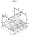
- the device for heating with solar energy mainly consists of a mirror construction 1 which is formed of a number of flat mirror strips 2 situated next to one another which are mounted on a frame 3 in a rotating manner according to their longitudinal direction or parallel to their longitudinal axis, and a collector 4 erected on top of it which is fixed stationary on the above-mentioned frame 3.
- the mirror strips 2 are flat and parallel to one another with their longitudinal direction.
- They are for example made of glass with a mirroring coat on the top side and preferably a coat which can resist sandstorms on the bottom side, such as a coat on the basis of rubber or plastic.
- They have a width of for example almost 50 cm, a length of about 3 m and a thickness of 3 mm.
- Every mirror strip 2 can rotate. As is represented in detail in figure 2, every mirror strip 2 is hooked on a frame 6 made of aluminium profiles by means of clamps 5, which frame is in turn fixed on a tube 8 by means of clamping brackets 7, which tube is mounted in a bearing 3 every three metres which is fixed on a horizontal cross-latch 10 which is part of the frame 3.
- All these cross-latches 10 are fixed with their ends to the rest of the frame 3, namely to standing profiles 11 or 12, at a height of about 1.5 m above the ground, but adjustable in height.
- cwo profiles 12 in a longitudinal side are erected three shorter profiles 11, for example one shorter profile 11 every three metres.
- the profiles 11 expend up to a distance above the mirror construction 1 and their top ends are connected to one another and to the profiles 12 by means of longitudinal profiles 13 in the longitudinal sides.
- the standing profiles 12 are considerably higher than the profiles 11 and their top ends are connected to one another by means of horizontal cross-sectional profiles 14.
- the standing profiles 11 and 12 are fixed to a concrete foundation 15.
- Over the two longitudinal profiles 13 may possibly ride a trolley which is not represented in the figures for maintaining, washing or repairing the mirror construction
- Means 16 are provided to rotate the mirror strips 2 as a function of the position of the sun, during the day as the mirror strips are directed with their longitudinal direction northward/southward.
- These means 15, which are only represented in figures 5 to 8 for clarity's sake, contain a sprocket wheel 17 on one end of every tube 8 which is connected to a sprocket wheel 19 via a chain 13 which is driven by a drive consisting of a stepping motor 20.
- These means 16 further contain an electronic control 21 which controls this stepping motor 20 as a function of the position of the sun, such that the mirror strips 2 can follow the sun.
- the length of the device in the longitudinal direction of the mirror strips 2 is unlimited, and this length may amount to one kilometre.
- the chain 18 extends around all the sprocket wheels 17 and the means 16 only have a single stepping motor 20 which drives all the sprocket wheels 17 via a sprocket wheel 19 and the chain 18, and thus rotates all the mirror strips 2 simultaneously and to the same extent.
- Each collector 4 is situated at a height above the mirror construction 1 which is for example half of the width of the mirror construction, for example at a height of twelve metres. However, the height can also be less and amount to for example six metres.
- collectors 4 extends in the longitudinal direction of the mirror strips 2.
- this collector 4 contains a metal, preferably a steel tube 22 of for example 6 inches (about 15 cm) long which is surrounded by double-walled glass tubes 23-24.
- a metal preferably a steel tube 22 of for example 6 inches (about 15 cm) long which is surrounded by double-walled glass tubes 23-24.
- glass tubes are not permeable to hydrogen, they are less expensive and they can have a smaller diameter.
- the outer tube-shaped wall 23 of the tubes 23-24 is translucent, but the inner tube-shaped wall 24 is coated with a black, heat-absorbing layer on the outside which has for example been sputtered onto it.
- the walls 23 and 24 are closed, and there is a vacuum between these walls 23 and 24 which are for example situated at a distance of about 1 mm from one another.
- This double-walled tube 23-24 is made of heat-resistant glass, for example glass which is known under the brandname Pyrex.
- the inner, black wall 24 can be heated up to temperatures of 300 to 500°C.
- This tube 23-24 is up to 4 metres long, and in order to make it possible for the inner wall 24 to expand, expansion bellows 25 are provided at one end of the outer wall 23, preferably made of tempered glass which has been fused to the rest of the glass wall 23.
- glass rings 26 are clasped around said inner wall 24, for example by providing them over the wall 24 when they are hot and by making them shrink by cooling them, which make contact with the outer wall 23 only locally so as to limit the heat transfer.
- a medium 27 which transfers heat for example steel wool surrounded by a thin aluminium sheet having a thickness of for example 0.3 mm, which is closely connected to the tube 22 and the wall 24.
- the double-walled tube 23-24 rests on the steel tube 22 through the agency of said medium 27.
- the tube 22 extends over the entire length of the mirror strips 2, but it can also extent over several series of mirror strips 2 or mirror constructions 1 and even have a length of 1 kilometre.
- the double-walled tube 23-24 only has a length of about 3 m, and several tubes 23-24 are provided one after the other around the steel tube 22 in the collector 4.
- the steel tube 22 is suspended to a trolley 29 by means of a suspension 28 rolling over a I-profile 30 of the frame 3, as is schematically represented in figure 4, and into more detail in figures 9 and 10.
- the trolley 29 is a U-profile whose two legs carry two small wheels 32 on their sides turned to one another. As is represented in figure 10, the front and rear wheels 32 are not placed on one and the same axis, but they are shifted in relation to one another in the driving direction, such that only one wheel 32 at a time rides over an expansion joint 31 while the trolley 29 is still resting with three wheels 32 on the I-profile 30. Thus, the trolley 29 is prevented from swinging as it rides over an expansion joint 31.
- the suspension 23 may consist of a first bar 33 which is screwed in a bush 34 which is welded on the steel tube 22 and which is surrounded by insulating material 35 between the ends of two neighbouring tubes 23-24 on the one hand, and which is screwed in a sleeve 36 on the other hand, and of a second bar 37 which is welded onto the trolley 29 and which is also screwed in the above-mentioned sleeve 36, such that, as the sleeve 36 turns, the bars 33 and 37 are drawn towards one another or are moved away from one another.
- the screw thread is directed in one and the same direction on both ends of the bar 33, but the screw threads on both ends screwed in the sleeve 36 are directed in the opposite sense.
- the collector 4 further contains a number of reflectors 38 which each consist of two longitudinal mirrors which are fixed to one another in the length above the glass tube 23-24 and which form a cap over the heat-absorbing pipe formed by the wall 24.
- the cross section of each mirror is a part, for example half, of a parabola.
- the reflectors 38 are suspended on a cross-sectional profile 40 by means of bars 39 which is fixed to the bottom side of the I-profile 30.
- Each reflector 38 is directed with its mirroring side on this wall 24 which is practically situated on the focal line of the two parabolic halves of this reflector 38.
- the reflector 38 has a length which is almost equal to the length of a double-walled glass tube 23-24, and the collector 4 has several of those reflectors 38 which are situated in line above the mirror construction 1.
- the opening at the bottom of the reflector 38 is calculated such that the solar rays which are reflected by all the mirror strips 2 of the mirror construction 1 fall in it and are thus reflected towards the inner wall 24 of the glass tube 23-24, insofar as they did not fall directly on this wall 24.
- this opening is such that it can collect an angle of rays of 90°, and it is for example about 72 cm.
- the angle can be larger, for example up to 135°.
- the length of the mirror strips 2 is limited to for example 3 m, but several mirror constructions 1 can be put one after the other in the longitudinal direction, whereby the tubes 8 of a number of mirror strips 2 or even all the mirror strips 2 situated in line can form an uninterrupted whole, so that a single stepping motor 20 can simultaneously rotate a number of these mirror strips 2 which are coupled to one another, or all of them at once.
- frame 3 and among others the longitudinal profiles 13 and the I-profile 30, abstracting from the expansion joints 31, may continue uninterruptedly over several series of mirror constructions 1.
- mirror constructions or mirror constructions situated one after the other in the longitudinal direction may also be situated next to one another in the cross direction.
- the mirror strips can be rotated against the direction of the wind with their protected back side.
- the device has a large efficiency. Only for a very short period in the early morning or late in the evening, the mirror strips may cast a shadow on a neighbouring mirror strip. During the rest of the day, little solar energy is lost due to shadows.
- the mirror strips 2 are directed with their longitudinal direction in the north/south direction.
- the three above-described collectors 4 are suspended to a I-profile 30, in that the mirror strips 2 have a different inclination in their cross direction and in that they are all driven by one.
- One of the three collectors 4 is erected in the middle, as in the above-mentioned embodiment, whereas the other two are situated above the longitudinal edges, to the east and to the west respectively of this middle collector 4.
- the mirror strips 2 are inclined such that they coincide with two longitudinal semi-parabolas which have been divided into segments and whereby the segments have been flattened and lowered in one and the same horizontal plane, and whereby the two semi-parabolas are practically parallel to one another.
- the mirror strips 2 which coincide with the one semi-parabola reflect towards one collector 4, whereas those coinciding with the other semi-parabola reflect towards another collector 4, whereby, when the sun has reached its highest point, all the mirror strips 2 are rotated together over an angle, so that they each reflect towards another collector 4.
- This angle is 22.5° when the width of the mirror construction 1 is equal to twice the height at which the collectors 4 are situated, and the distance between the collectors 4 is thus equal to this height.
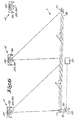
- the mirror strips 2 are represented at the time the sun stands on the horizon in the east.
- the first series or half of the mirror strips 2 situated on the side of the sun reflect the collected solar rays towards the collector 4 situated eastward.
- the other series or half of the mirror strips 2 reflect towards the middle collector 4.
- the mirror strips 2 are all continuously rotated by the means 16, but they keep reflecting towards the above-mentioned collectors 4 as the sun rises until they take the position in which they are represented in figure 6, when the sun is at its highest point. Before noon, they are rotated over 45° in total.
- the mirror strips 2 of the first series now reflect towards the middle collector 4 and the other mirror strips 2 towards the collector 4 situated westward.
- the angle between the incident solar rays and the solar rays reflected to a collector 4, which is represented for some mirror strips 2 in figures 5 to 8, is smaller than 90°, so that the efficiency of the device is excellent.
- the means 16 have a simple construction and the tracking of the sun is rather easy.
- additional mirror strips 2 can be provided as is represented by means of a dashed line in figures 5 to 8, in particular one or several series of mirror strips 2 which coincide with a segmented semi-parabola, but for every series also one additional collector 4.
- the additional series of mirror strips 2 situated eastward will reflect towards the collector 4 of the above-described mirror construction 1 situated the most eastward in the afternoon.
- an additional series situated westward will reflect towards the collector 4 of the above-described mirror construction 1 situated the most westward before noon.
- mirror construction is divided in mirror strips 2, it is possible to put one or several mirror strips 2 entirely or partly off-duty, for example by tilting them separately so that they are no longer directed towards the sun, so as to thus adjust the total amount of solar energy which is collected by the device.
Landscapes
- Engineering & Computer Science (AREA)
- Chemical & Material Sciences (AREA)
- Mechanical Engineering (AREA)
- Sustainable Development (AREA)
- Sustainable Energy (AREA)
- Thermal Sciences (AREA)
- Physics & Mathematics (AREA)
- Combustion & Propulsion (AREA)
- Life Sciences & Earth Sciences (AREA)
- General Engineering & Computer Science (AREA)
- Optical Elements Other Than Lenses (AREA)
- Photovoltaic Devices (AREA)
- Mounting And Adjusting Of Optical Elements (AREA)
- Mirrors, Picture Frames, Photograph Stands, And Related Fastening Devices (AREA)
- Road Signs Or Road Markings (AREA)
Claims (16)
- Vorrichtung zum Heizen mit Sonnenenergie, welche Vorrichtung zumindest eine Spiegelkonstruktion (1), die auf einem Rahmen (3) montiert ist und die auf die Sonne gerichtet werden kann, und zumindest drei Kollektoren (4) in gleichem Abstand voneinander umfasst, die sich parallel zur Spiegelkonstruktion (1) erstrecken, um die von der Spiegelkonstruktion (1) reflektierte Sonnenstrahlung zu sammeln, wobei die Spiegelkonstruktion (1) eine Anzahl nahezu flacher Spiegelstreifen (2) umfasst, die sich nebeneinander in der Längsrichtung der Kollektoren (4) und mit ihrer Längsrichtung nordwärts/südwärts erstrecken und die jeder so auf dem Rahmen (3) angebracht sind, dass sie um ihre Längsrichtung rotieren können, während die Kollektoren (4) in Bezug zum Rahmen (3) stationär sind, wobei die Spiegelstreifen (2) mit ihren Rotationsachsen in einer nahezu horizontalen Ebene gelegen sind, wobei die Vorrichtung Mittel (16) umfasst, um die Spiegelstreifen (2) und die Spiegeloberfläche der Spiegelstreifen (2) so zu rotieren, dass die auf besagte Oberfläche auftreffenden Sonnenstrahlen zu den Kollektoren (4) hin reflektiert werden können, und Steuermittel (21), die die Mittel (16) zum Rotieren in Funktion der Position der Sonne steuern, dadurch gekennzeichnet, dass, wenn drei benachbarte Kollektoren (4) in Betracht gezogen werden, die darunter befindlichen Spiegelstreifen (2) in zwei Serien aufgeteilt sind, wobei die Spiegelstreifen (2) einer Serie auf den in der Mitte befindlichen Kollektor (4) reflektieren, während die Spiegelstreifen (2) der anderen Serie auf den einen der beiden über der Serie gelegenen anderen Kollektoren (4) reflektieren, wobei die Steuermittel (21) die Mittel (16) so steuern, dass sie derart rotiert werden, dass, morgens, eine erste Serie von zwischen dem mittleren Kollektor (4) und dem östlich davon gelegenen Kollektor (4) befindlichen Kollektoren zu diesem letzteren Kollektor (4) hin reflektiert, während die zweite Serie von Spiegelstreifen (2), die sich zwischen dem mittleren Kollektor (4) und dem westlich davon befindlichen Kollektor (4) befinden, zum mittleren Kollektor (4) hin reflektiert und dass, nachdem die Sonne tagsüber ihren höchsten Punkt passiert hat, d.h. am Nachmittag, die erste Serie von Spiegelstreifen (2) zum mittleren Kollektor (4) hin reflektiert und die zweite Serie von Spiegelstreifen (2) zu dem westlich davon befindlichen Kollektor (4) hin reflektiert.
- Vorrichtung gemäß Anspruch 1, dadurch gekennzeichnet, dass die Spiegelkonstruktion (1) aus zwei segmentierten, halbparabolförmigen Spiegeln besteht, die sich parallel zueinander erstrecken und deren Segmente abgeflacht und in einer horizontalen Ebene plaziert wurden.
- Vorrichtung gemäß Anspruch 1 oder 2, dadurch gekennzeichnet, dass die Spiegelkonstruktion (1) um zumindest eine zusätzliche Serie von Spiegelstreifen (2) und um einen zusätzlichen Kollektor (4) pro Serie erweitert wurde.
- Vorrichtung gemäß einem der vorgenannten Ansprüche, dadurch gekennzeichnet, dass die Mittel (16) zum Rotieren der Spiegelstreifen (2) Mittel sind, um zumindest eine Anzahl der Spiegelstreifen (2) oder alle Spiegelstreifen (2) zusammen zu rotieren, gleichzeitig und im selben Ausmaß.
- Vorrichtung gemäß den Ansprüchen 1 und 4, dadurch gekennzeichnet, dass die Mittel (16) zum Rotieren der Spiegelstreifen (2) Mittel sind, um zumindest all die Spiegelstreifen (2) zu rotieren, die sich zwischen zwei Kollektoren (4) befinden.
- Vorrichtung gemäß Anspruch 4 oder 5, dadurch gekennzeichnet, dass die Mittel (16) zum Rotieren zumindest einer Anzahl von Spiegelstreifen (2) gleichzeitig ein Rad, beispielsweise ein Kettenrad (17) oder ein Zahnrad, an zumindest einem Ende jedes dieser Spiegelstreifen (2) aufweisen, ein Endloselement, beispielsweise eine Kette (18) oder einen Zahnriemen, das mit all diesen Rädern zusammenwirkt, und Antriebsmittel (20) zum Antrieb dieses Elements.
- Vorrichtung gemäß einem der vorgenannten Ansprüche, dadurch gekennzeichnet, dass der Kollektor (4) zumindest eine wärmeabsorbierende Röhre (23-24) und zumindest einen auf die dazwischen befindliche Röhre (23-24) gerichteten Reflektor (36) aufweist, welcher wie eine Kappe über der Röhre (23-24) errichtet ist, um die von der Spiegelkonstruktion (1) reflektierten Sonnenstrahlen zu sammeln und um sie zur Röhre (23-24) zu reflektieren.
- Vorrichtung gemäß Anspruch 7, dadurch gekennzeichnet, dass der Reflektor (38) aus zwei parabolförmigen gebogenen Spiegeln besteht.
- Vorrichtung gemäß Anspruch 7 oder 8, dadurch gekennzeichnet, dass die Röhre (23-24) eine doppelwandige Glasröhre ist, deren innere röhrenförmige Wand (24) außen mit einem wärmeabsorbierenden Material beschichtet ist und deren äußere röhrenförmige Wand lichtdurchlässig ist, und ein Vakuum zwischen beiden Wänden (23 und 24) aufweist.
- Vorrichtung gemäß Anspruch 9, dadurch gekennzeichnet, dass ein Metallrohr (22) sich durch die Röhre (23-24) erstreckt, während der Raum zwischen diesem Metallrohr (22) und der Röhre (23-24) mit einem wärmeübertragenden Medium (27), wie etwa Stahlwolle, gefüllt ist.
- Vorrichtung gemäß Anspruch 9 oder 10, dadurch gekennzeichnet, dass Ausdehnungsbälge (25) in der inneren Wand (24) angebracht sind.
- Vorrichtung gemäß Anspruch 11, dadurch gekennzeichnet, dass Ringe (26) zwischen den zwei Wänden (23 und 24) der Röhre angebracht sind, die vorzugsweise nur örtlich mit der äußeren Wand (23) in Kontakt sind.
- Vorrichtung gemäß einem der Ansprüche 11 bis 12, dadurch gekennzeichnet, dass über der Spiegelkonstruktion (1) mehrere Röhren (23-24) hintereinander um ein einziges Metallrohr (22) herum angebracht sind und dass diese Röhren (23-24) von diesem Metallrohr (22) getragen werden.
- Vorrichtung gemäß einem der vorgenannten Ansprüche, dadurch gekennzeichnet, dass der Kollektor (4) ein Metallrohr (22) für zu erhitzendes Fluid umfasst, das in regelmäßigen Abständen an einem längsgerichteten Profil (30) aufgehängt ist, das Teil des Rahmens (3) ist, mittels eines Wagens (29), der über dieses längsgerichtete Profil fahren kann.
- Vorrichtung gemäß Anspruch 14, dadurch gekennzeichnet, dass das längsgerichtete Profil (30) mit Dehnfugen (31) versehen ist und dass der Wagen (29) zwei Vorderund zwei Hinterräder (32) umfasst, die nicht auf derselben Achse plaziert sind, sondern die in Bezug zueinander in Fahrtrichtung verschoben sind.
- Vorrichtung gemäß Anspruch 14 oder 15, dadurch gekennzeichnet, dass das Metallrohr (30) mittels einer Aufhängung aufgehängt ist, die zwei Stangen (33 und 37) umfasst, die in einer Muffe (36) zusammengeschraubt sind, sodass sie durch Drehen der Muffe in Bezug zueinander ausgerichtet werden können.
Applications Claiming Priority (3)
| Application Number | Priority Date | Filing Date | Title |
|---|---|---|---|
| NL1008356 | 1998-02-19 | ||
| NL1008356A NL1008356C2 (nl) | 1998-02-19 | 1998-02-19 | Inrichting voor het verwarmen met zonne-energie. |
| PCT/BE1999/000017 WO1999042765A1 (en) | 1998-02-19 | 1999-02-09 | Device for heating with solar energy |
Publications (2)
| Publication Number | Publication Date |
|---|---|
| EP1056978A1 EP1056978A1 (de) | 2000-12-06 |
| EP1056978B1 true EP1056978B1 (de) | 2002-10-09 |
Family
ID=19766573
Family Applications (1)
| Application Number | Title | Priority Date | Filing Date |
|---|---|---|---|
| EP99903546A Expired - Lifetime EP1056978B1 (de) | 1998-02-19 | 1999-02-09 | Vorrichtung zur heizung mittels sonnenenergie |
Country Status (17)
| Country | Link |
|---|---|
| US (1) | US6349718B1 (de) |
| EP (1) | EP1056978B1 (de) |
| CN (1) | CN1143999C (de) |
| AP (1) | AP2000001880A0 (de) |
| AU (1) | AU752838B2 (de) |
| BR (1) | BR9907899A (de) |
| CU (1) | CU22721A3 (de) |
| EA (1) | EA002295B1 (de) |
| ES (1) | ES2185312T3 (de) |
| IL (1) | IL137574A0 (de) |
| MA (1) | MA24762A1 (de) |
| NL (1) | NL1008356C2 (de) |
| OA (1) | OA11478A (de) |
| PT (1) | PT1056978E (de) |
| TN (1) | TNSN99023A1 (de) |
| TR (1) | TR200002393T2 (de) |
| WO (1) | WO1999042765A1 (de) |
Cited By (5)
| Publication number | Priority date | Publication date | Assignee | Title |
|---|---|---|---|---|
| WO2008022409A1 (en) * | 2006-08-25 | 2008-02-28 | Solar Heat And Power Pty Limited | Energy collector system having east-west extending linear reflectors |
| US8378280B2 (en) | 2007-06-06 | 2013-02-19 | Areva Solar, Inc. | Integrated solar energy receiver-storage unit |
| US8739512B2 (en) | 2007-06-06 | 2014-06-03 | Areva Solar, Inc. | Combined cycle power plant |
| US8807128B2 (en) | 2007-08-27 | 2014-08-19 | Areva Solar, Inc. | Linear fresnel solar arrays |
| US9022020B2 (en) | 2007-08-27 | 2015-05-05 | Areva Solar, Inc. | Linear Fresnel solar arrays and drives therefor |
Families Citing this family (64)
| Publication number | Priority date | Publication date | Assignee | Title |
|---|---|---|---|---|
| BE1013565A3 (nl) | 2000-06-20 | 2002-04-02 | Suria Holdings Sarl | Inrichting voor het benutten van zonne-energie. |
| BE1013566A3 (nl) | 2000-06-20 | 2002-04-02 | Suria Holdings Sarl | Inrichting voor het benutten van zonne-energie en werkwijze voor het vervaardigen van een reflector daarvoor. |
| DE10032882A1 (de) | 2000-07-06 | 2002-01-17 | Bayer Ag | Anlage zur Nutzung von Solarenergie |
| BE1013638A3 (nl) * | 2000-08-07 | 2002-05-07 | Ven Juha | Inrichting voor het benutten van geconcentreerde zonne-energie. |
| BE1013693A3 (nl) | 2000-09-19 | 2002-06-04 | Suria Holdings Sarl | Werkwijze en inrichting voor het vervaardigen van stoom met zonne-energie. |
| DE10248064B4 (de) * | 2002-10-11 | 2007-11-22 | Deutsches Zentrum für Luft- und Raumfahrt e.V. | Solar-Receivervorrichtung zur solarthermischen Erhitzung eines Wärmeaufnahmemediums |
| US7192146B2 (en) * | 2003-07-28 | 2007-03-20 | Energy Innovations, Inc. | Solar concentrator array with grouped adjustable elements |
| US7021560B2 (en) * | 2003-09-25 | 2006-04-04 | Deka Products Limited Partnership | System and method for aerosol delivery |
| BRPI0507752A (pt) * | 2004-02-17 | 2007-12-18 | Solar Heat And Power Pty Ltd | estrutura coletora solar multi-tubo |
| RS20100474A (sr) * | 2004-05-28 | 2010-12-31 | Aleksej ŠPINDLER | Solarni kolektori sa razmaknutim refleksnim ogledalima i primena solarnih kolektora za predgrevanje vazduha |
| WO2006000834A1 (en) * | 2004-06-24 | 2006-01-05 | Heliodynamics Limited | Solar energy collection systems |
| US7454990B2 (en) * | 2005-03-18 | 2008-11-25 | Atlas Material Testing, Llc | Variably controlled accelerated weathering test apparatus |
| DE102005018657A1 (de) * | 2005-04-21 | 2006-10-26 | Lokurlu, Ahmet, Dr. | Kollektor und Kollektoranordnung zur Gewinnung von Wärme aus einfallender Strahlung |
| ATE508336T1 (de) * | 2005-08-20 | 2011-05-15 | Novatec Biosol Ag | Fresnel-solar-kollektor-anordnung |
| ES2292368B2 (es) | 2007-05-09 | 2008-09-16 | Universidad Politecnica De Madrid | Vierteaguas con adecuacion de su derrame para proteger los huecos de edificios y su interior de la radiacion solar directa reflejada desde su superficie. |
| US20090126364A1 (en) * | 2007-06-06 | 2009-05-21 | Ausra, Inc. | Convective/radiative cooling of condenser coolant |
| WO2009023063A2 (en) * | 2007-06-13 | 2009-02-19 | Ausra, Inc. | Solar energy receiver having optically inclined aperture |
| US20090000653A1 (en) * | 2007-06-29 | 2009-01-01 | Edwards Oliver J | Solar power harvester with reflective border |
| US8766091B2 (en) * | 2007-06-29 | 2014-07-01 | Oliver J. Edwards | Solar power harvester |
| US8683994B2 (en) * | 2008-02-20 | 2014-04-01 | Corning Incorporated | Solar heat collection element with glass-ceramic central tube |
| CA2725421A1 (en) * | 2008-05-13 | 2009-11-19 | Chromasun Pty Ltd | Concentrator for solar radiation |
| PT2161516E (pt) * | 2008-09-03 | 2012-01-12 | Novatec Solar Gmbh | Sistema térmico solar |
| FR2937122A1 (fr) * | 2008-10-15 | 2010-04-16 | Pascal Sylvain Moigne | Panneau solaire a concentration et poursuite solaire |
| US8490620B1 (en) | 2008-10-23 | 2013-07-23 | Lockheed Martin Corporation | In-ground solar trough |
| WO2010067209A2 (en) * | 2008-12-08 | 2010-06-17 | Kyoto Energy Ltd. | Mosaic solar collector |
| US9091459B2 (en) * | 2009-02-28 | 2015-07-28 | Richard Welle | Segmented fresnel solar concentrator |
| ES2375389B1 (es) * | 2009-03-02 | 2012-09-27 | Abengoa Solar New Technologies S.A. | Planta de concentración solar tipo fresnel con reconcentrador secundario optimizado. |
| ES2325110B1 (es) * | 2009-03-04 | 2010-07-06 | Juan Martinez-Val Piera | Colector solar cilindro-parabolico con tubo absorbedor fijo colgante. |
| US8978641B2 (en) * | 2009-03-16 | 2015-03-17 | B. Shawn Buckley | Solar energy module |
| US20100294266A1 (en) * | 2009-05-22 | 2010-11-25 | Fung Tak Pui Jackson | Concentrated solar thermal energy collection device |
| CN102725233A (zh) * | 2009-09-16 | 2012-10-10 | 101摄氏度有限责任公司 | 太阳能转换系统 |
| AU2010303499B2 (en) * | 2009-10-07 | 2015-07-30 | Areva Solar, Inc. | Multi-tube solar thermal receiver |
| US20110155126A1 (en) * | 2009-12-29 | 2011-06-30 | De Luca Nicholas P | Wave generated energy focusing lens and reflector for solar concentration, collection, and harnessing |
| WO2011090742A2 (en) | 2009-12-29 | 2011-07-28 | De Luca Nicholas P | Wave generated energy focusing lens and reflector for solar concentration, collection, and harnessing |
| DE102010014787B4 (de) * | 2010-04-13 | 2013-11-14 | Solar Power Group Gmbh | Solarthermische Anlage |
| US20110271999A1 (en) | 2010-05-05 | 2011-11-10 | Cogenra Solar, Inc. | Receiver for concentrating photovoltaic-thermal system |
| CN102252434B (zh) * | 2010-05-19 | 2013-11-27 | 德阳市东联机械成套设备厂 | 太阳能反射器 |
| ES2345427B2 (es) | 2010-05-19 | 2011-07-19 | Universidad Politecnica De Madrid (90 %) | Dispositivo de concentracion de la radiacion solar, con espejos y receptor longitudinales. |
| ES2378198B1 (es) * | 2010-07-19 | 2012-12-28 | Abengoa Solar New Technologies S.A. | Nueva disposición de getter no evaporable para tubo colector solar. |
| CN101943793B (zh) * | 2010-07-30 | 2012-11-07 | 杭州天升实业有限公司 | 采用平板式聚光镜的太阳能集热系统 |
| AT510324B1 (de) * | 2010-08-23 | 2012-08-15 | Hartmut Dipl Ing Schneider | Spiegelmodul |
| US9893223B2 (en) | 2010-11-16 | 2018-02-13 | Suncore Photovoltaics, Inc. | Solar electricity generation system |
| EP2771614A4 (de) * | 2011-10-25 | 2015-11-18 | Univ British Columbia | Spiegelanordnung zum umlenken des sonnenlichts |
| ITMI20111947A1 (it) * | 2011-10-26 | 2013-04-27 | En Rinnovabili Altern Ative S R L Fab | Impianto solare a concentrazione |
| ITMI20111946A1 (it) * | 2011-10-26 | 2013-04-27 | En Rinnovabili Altern Ative S R L Fab | Impianto a concentrazione dei raggi luminosi per la conversione di energia solare almeno in energia termica |
| US20130146124A1 (en) * | 2011-11-23 | 2013-06-13 | Smart Solar International, Inc. | Large-scale integrated radiant energy collector |
| DE102011088829B3 (de) * | 2011-12-16 | 2013-04-04 | Schott Solar Ag | Receiversystem für eine Fresnel-Solaranlage |
| DE102011088830B3 (de) * | 2011-12-16 | 2013-02-07 | Schott Solar Ag | Receiversystem für eine Fresnel-Solaranlage |
| ES2427020B1 (es) * | 2012-03-26 | 2014-09-22 | Iniciativas Energéticas Del Sur Sl | Planta de concentración solar con absorbedor plano optimizado |
| ES2482665B1 (es) * | 2012-10-02 | 2015-05-11 | Benito RESA RODRIGO | Secadero ecosostenible para productos agrícolas |
| US20140124014A1 (en) | 2012-11-08 | 2014-05-08 | Cogenra Solar, Inc. | High efficiency configuration for solar cell string |
| US9270225B2 (en) | 2013-01-14 | 2016-02-23 | Sunpower Corporation | Concentrating solar energy collector |
| WO2015144138A2 (de) | 2014-03-24 | 2015-10-01 | Frenell Gmbh | Absorbersystem |
| EP3015789A1 (de) | 2014-10-31 | 2016-05-04 | Heliovis AG | Vorrichtung zur konzentration von sonnenstrahlung mit aufblasbarem konzentratorkissen |
| AT516019B1 (de) * | 2014-10-31 | 2016-02-15 | Heliovis Ag | Vorrichtung zur Halterung eines aufblasbaren Konzentrator-Kissens |
| EP3015788A1 (de) * | 2014-10-31 | 2016-05-04 | Heliovis AG | Vorrichtung zur konzentration von sonnenstrahlung mit aufblasbarem konzentratorkissen |
| EP3015787A1 (de) | 2014-10-31 | 2016-05-04 | Heliovis AG | Vorrichtung zur konzentration von sonnenstrahlung mit aufblasbarem konzentratorkissen |
| FR3031168B1 (fr) * | 2014-12-30 | 2021-07-23 | Commissariat Energie Atomique | Infrastructure de champ de reflecteurs |
| CN105423574B (zh) * | 2015-12-30 | 2017-11-14 | 南京工业大学 | 集热器与聚光器分离的抛物槽式太阳能聚光集热器 |
| EP3524901A1 (de) * | 2016-01-25 | 2019-08-14 | Universidade de Évora | Kompakter linearer reflektierender fresnelscher sonnenkonzentrator für direkten salzschmelzebetrieb als wärmeübertragungsfluid in evakuierten rohren |
| WO2017131544A1 (en) * | 2016-01-25 | 2017-08-03 | Universidade De Évora | Compact linear fresnel reflective solar concentrator designed for direct molten salt operation as heat transfer fluid in evacuated tubes |
| IT201700021827A1 (it) * | 2017-02-27 | 2018-08-27 | Suberia Systems Srl | Impianto solare a concentrazione |
| CN107477885B (zh) * | 2017-08-04 | 2019-09-24 | 王煊 | 太阳能聚光集热单元 |
| CN109373613B (zh) * | 2018-10-30 | 2024-02-06 | 中国电力工程顾问集团西北电力设计院有限公司 | 一种基于分段抛物线函数的反射镜及槽式集热器 |
Family Cites Families (16)
| Publication number | Priority date | Publication date | Assignee | Title |
|---|---|---|---|---|
| FR1520370A (fr) * | 1963-11-14 | 1968-04-12 | Installation de chauffage de fluide par l'énergie solaire | |
| US3861379A (en) * | 1974-03-05 | 1975-01-21 | Jr Henry Anderson | Low profile solar ray concentrator |
| NL7610401A (nl) * | 1976-09-20 | 1978-03-22 | Philips Nv | Zonnecollector voorzien van zonnevolgmiddelen. |
| US4229076A (en) * | 1976-10-26 | 1980-10-21 | Edsel Chromie | Solar energy concentrator |
| US4186724A (en) * | 1976-11-22 | 1980-02-05 | American Solar | Solar energy collector |
| US4243018A (en) * | 1978-06-19 | 1981-01-06 | Kawneer Company, Inc. | Solar energy concentrator |
| IT1193452B (it) * | 1979-07-20 | 1988-06-22 | Mantinger Karl | Pannello solare a concentrazione tramite specchi piani orientabili |
| BE888400A (nl) | 1981-04-14 | 1981-10-14 | Ven Juha | Toestel voor het geconcentreerd gebruik van zonnestralen, |
| EP0076455B1 (de) * | 1981-10-01 | 1987-04-29 | Joachim Wenzel | Solarkraftwerk |
| FR2517034A3 (fr) * | 1981-11-25 | 1983-05-27 | Geres | Capteur solaire a concentration lineaire |
| CH657443A5 (de) * | 1982-06-16 | 1986-08-29 | Atlantis Energie Ag | Einrichtung zum automatischen richten von durch einen reflektor konzentrierter sonnenstrahlung. |
| FR2608741B1 (fr) * | 1986-12-19 | 1990-05-25 | Sevelinge Gerard | Capteur solaire a concentration. lineaire a lames mobiles |
| US5374317A (en) * | 1990-09-26 | 1994-12-20 | Energy Systems Solar, Incorporated | Multiple reflector concentrator solar electric power system |
| US5203318A (en) * | 1992-08-06 | 1993-04-20 | Maxime Chauvet | Sun tracking solar concentrator |
| AUPN201395A0 (en) * | 1995-03-28 | 1995-04-27 | University Of Sydney, The | Solar energy collector system |
| US5673684A (en) * | 1996-01-26 | 1997-10-07 | Myles, Iii; John F. | Tracking solar energy concentrating system having a circular primary reflector and a tracking secondary compound parabolic reflector |
-
1998
- 1998-02-19 NL NL1008356A patent/NL1008356C2/nl not_active IP Right Cessation
-
1999
- 1999-02-09 CN CNB998031186A patent/CN1143999C/zh not_active Expired - Fee Related
- 1999-02-09 BR BR9907899-6A patent/BR9907899A/pt active Search and Examination
- 1999-02-09 AP APAP/P/2000/001880A patent/AP2000001880A0/en unknown
- 1999-02-09 TR TR2000/02393T patent/TR200002393T2/xx unknown
- 1999-02-09 AU AU24050/99A patent/AU752838B2/en not_active Ceased
- 1999-02-09 EP EP99903546A patent/EP1056978B1/de not_active Expired - Lifetime
- 1999-02-09 IL IL13757499A patent/IL137574A0/xx unknown
- 1999-02-09 ES ES99903546T patent/ES2185312T3/es not_active Expired - Lifetime
- 1999-02-09 US US09/600,893 patent/US6349718B1/en not_active Expired - Fee Related
- 1999-02-09 EA EA200000774A patent/EA002295B1/ru not_active IP Right Cessation
- 1999-02-09 WO PCT/BE1999/000017 patent/WO1999042765A1/en not_active Ceased
- 1999-02-09 PT PT99903546T patent/PT1056978E/pt unknown
- 1999-02-16 TN TNTNSN99023A patent/TNSN99023A1/fr unknown
- 1999-02-16 MA MA25464A patent/MA24762A1/fr unknown
-
2000
- 2000-08-11 CU CU20000185A patent/CU22721A3/es unknown
- 2000-08-11 OA OA1200000222A patent/OA11478A/en unknown
Cited By (5)
| Publication number | Priority date | Publication date | Assignee | Title |
|---|---|---|---|---|
| WO2008022409A1 (en) * | 2006-08-25 | 2008-02-28 | Solar Heat And Power Pty Limited | Energy collector system having east-west extending linear reflectors |
| US8378280B2 (en) | 2007-06-06 | 2013-02-19 | Areva Solar, Inc. | Integrated solar energy receiver-storage unit |
| US8739512B2 (en) | 2007-06-06 | 2014-06-03 | Areva Solar, Inc. | Combined cycle power plant |
| US8807128B2 (en) | 2007-08-27 | 2014-08-19 | Areva Solar, Inc. | Linear fresnel solar arrays |
| US9022020B2 (en) | 2007-08-27 | 2015-05-05 | Areva Solar, Inc. | Linear Fresnel solar arrays and drives therefor |
Also Published As
| Publication number | Publication date |
|---|---|
| OA11478A (en) | 2004-05-04 |
| AU752838B2 (en) | 2002-10-03 |
| CN1291275A (zh) | 2001-04-11 |
| CN1143999C (zh) | 2004-03-31 |
| EA200000774A1 (ru) | 2001-04-23 |
| BR9907899A (pt) | 2000-10-17 |
| IL137574A0 (en) | 2001-07-24 |
| AP2000001880A0 (en) | 2000-09-30 |
| TR200002393T2 (tr) | 2001-01-22 |
| AU2405099A (en) | 1999-09-06 |
| PT1056978E (pt) | 2003-02-28 |
| EA002295B1 (ru) | 2002-02-28 |
| NL1008356C2 (nl) | 1999-08-20 |
| WO1999042765A1 (en) | 1999-08-26 |
| ES2185312T3 (es) | 2003-04-16 |
| US6349718B1 (en) | 2002-02-26 |
| EP1056978A1 (de) | 2000-12-06 |
| CU22721A3 (es) | 2001-11-16 |
| MA24762A1 (fr) | 1999-10-01 |
| TNSN99023A1 (fr) | 2001-12-31 |
Similar Documents
| Publication | Publication Date | Title |
|---|---|---|
| US6349718B1 (en) | Device for heating with solar energy | |
| US4323052A (en) | Solar energy system | |
| CA1119909A (en) | Solar energy collecting system | |
| US4132219A (en) | Extra-focal, convective suppressing solar collector | |
| US4602613A (en) | Solar energy concentrating and collecting arrangement | |
| US4203426A (en) | Solar energy converter carousel mounted rack | |
| US9349899B2 (en) | Modular solar systems facilitating rapid assembly | |
| US4015585A (en) | Solar heating apparatus | |
| US8333186B2 (en) | Parabolic trough solar reflector with an independently supported collector tube | |
| US4088120A (en) | Solar concentrator-collector | |
| US3990430A (en) | Solar energy collector system | |
| US4355630A (en) | Concentrating solar collector with tracking multipurpose targets | |
| US4602853A (en) | Solar energy concentrating and collecting arrangement | |
| MX2012003353A (es) | Sistema concentrador solar con reflectores primarios fijos y espejo secundario de articulacion. | |
| WO2012076949A1 (en) | A solar parabolic trough collector or reflector system | |
| US4184479A (en) | Greenhouse with stored solar energy capability | |
| CA1130671A (en) | Solar energy collector/reflector arrangement | |
| WO2010109508A2 (en) | Concentrating solar panel installation with azimuth orientation system | |
| RU2206837C2 (ru) | Солнечный модуль с концентратором (варианты) | |
| CN2674358Y (zh) | 太阳能聚热装置 | |
| MXPA00008140A (en) | Device for heating with solar energy | |
| JPS6125977B2 (de) | ||
| AU2011100679A4 (en) | Parabolic trough solar reflector with an independently supported collector tube | |
| EP3335246B1 (de) | Energieumwandlungssystem mit zweifacher nutzung | |
| RU1796755C (ru) | Крыша с солнцезащитным экраном |
Legal Events
| Date | Code | Title | Description |
|---|---|---|---|
| PUAI | Public reference made under article 153(3) epc to a published international application that has entered the european phase |
Free format text: ORIGINAL CODE: 0009012 |
|
| 17P | Request for examination filed |
Effective date: 20000814 |
|
| AK | Designated contracting states |
Kind code of ref document: A1 Designated state(s): CY ES GB IT PT Kind code of ref document: A1 Designated state(s): CY ES GR IT PT |
|
| GRAG | Despatch of communication of intention to grant |
Free format text: ORIGINAL CODE: EPIDOS AGRA |
|
| 17Q | First examination report despatched |
Effective date: 20010620 |
|
| GRAG | Despatch of communication of intention to grant |
Free format text: ORIGINAL CODE: EPIDOS AGRA |
|
| GRAH | Despatch of communication of intention to grant a patent |
Free format text: ORIGINAL CODE: EPIDOS IGRA |
|
| GRAH | Despatch of communication of intention to grant a patent |
Free format text: ORIGINAL CODE: EPIDOS IGRA |
|
| GRAA | (expected) grant |
Free format text: ORIGINAL CODE: 0009210 |
|
| AK | Designated contracting states |
Kind code of ref document: B1 Designated state(s): CY ES GR IT PT |
|
| RBV | Designated contracting states (corrected) |
Designated state(s): CY ES GR IT PT |
|
| REG | Reference to a national code |
Ref country code: GR Ref legal event code: EP Ref document number: 20020404492 Country of ref document: GR |
|
| PGFP | Annual fee paid to national office [announced via postgrant information from national office to epo] |
Ref country code: PT Payment date: 20030218 Year of fee payment: 5 |
|
| PGFP | Annual fee paid to national office [announced via postgrant information from national office to epo] |
Ref country code: GR Payment date: 20030227 Year of fee payment: 5 |
|
| REG | Reference to a national code |
Ref country code: PT Ref legal event code: SC4A Free format text: AVAILABILITY OF NATIONAL TRANSLATION Effective date: 20021218 |
|
| REG | Reference to a national code |
Ref country code: ES Ref legal event code: FG2A Ref document number: 2185312 Country of ref document: ES Kind code of ref document: T3 |
|
| PLBE | No opposition filed within time limit |
Free format text: ORIGINAL CODE: 0009261 |
|
| STAA | Information on the status of an ep patent application or granted ep patent |
Free format text: STATUS: NO OPPOSITION FILED WITHIN TIME LIMIT |
|
| 26N | No opposition filed |
Effective date: 20030710 |
|
| PG25 | Lapsed in a contracting state [announced via postgrant information from national office to epo] |
Ref country code: PT Free format text: LAPSE BECAUSE OF NON-PAYMENT OF DUE FEES Effective date: 20040831 |
|
| PG25 | Lapsed in a contracting state [announced via postgrant information from national office to epo] |
Ref country code: GR Free format text: LAPSE BECAUSE OF NON-PAYMENT OF DUE FEES Effective date: 20040903 |
|
| PG25 | Lapsed in a contracting state [announced via postgrant information from national office to epo] |
Ref country code: IT Free format text: LAPSE BECAUSE OF NON-PAYMENT OF DUE FEES Effective date: 20050209 |
|
| REG | Reference to a national code |
Ref country code: ES Ref legal event code: PC2A |
|
| PGFP | Annual fee paid to national office [announced via postgrant information from national office to epo] |
Ref country code: CY Payment date: 20120301 Year of fee payment: 14 |
|
| PGFP | Annual fee paid to national office [announced via postgrant information from national office to epo] |
Ref country code: ES Payment date: 20120228 Year of fee payment: 14 |
|
| PG25 | Lapsed in a contracting state [announced via postgrant information from national office to epo] |
Ref country code: CY Free format text: LAPSE BECAUSE OF NON-PAYMENT OF DUE FEES Effective date: 20130209 |
|
| REG | Reference to a national code |
Ref country code: ES Ref legal event code: FD2A Effective date: 20140409 |
|
| PG25 | Lapsed in a contracting state [announced via postgrant information from national office to epo] |
Ref country code: ES Free format text: LAPSE BECAUSE OF NON-PAYMENT OF DUE FEES Effective date: 20130210 |