EP1057149B1 - Flamm- und rauchdetektion - Google Patents
Flamm- und rauchdetektion Download PDFInfo
- Publication number
- EP1057149B1 EP1057149B1 EP99903175A EP99903175A EP1057149B1 EP 1057149 B1 EP1057149 B1 EP 1057149B1 EP 99903175 A EP99903175 A EP 99903175A EP 99903175 A EP99903175 A EP 99903175A EP 1057149 B1 EP1057149 B1 EP 1057149B1
- Authority
- EP
- European Patent Office
- Prior art keywords
- smoke
- detector
- fire
- radiation
- flame detector
- Prior art date
- Legal status (The legal status is an assumption and is not a legal conclusion. Google has not performed a legal analysis and makes no representation as to the accuracy of the status listed.)
- Expired - Lifetime
Links
Images





Classifications
-
- G—PHYSICS
- G08—SIGNALLING
- G08B—SIGNALLING SYSTEMS, e.g. PERSONAL CALLING SYSTEMS; ORDER TELEGRAPHS; ALARM SYSTEMS
- G08B17/00—Fire alarms; Alarms responsive to explosion
- G08B17/12—Actuation by presence of radiation or particles, e.g. of infrared radiation or of ions
Definitions
- the present invention relates to fire and smoke detection methodology and associated apparatus.
- Conventional smoke sensors utilize light scattering or smoke ionization measurements
- conventional temperature sensors used in fire detection utilize thermocouple measurements.
- Single channel flame detectors operate either in the ultraviolet (where solar radiation is totally absorbed by the earth's atmosphere) or in the infrared (where flame emission is primarily from hot CO 2 ) parts of the spectrum.
- Ultraviolet signals from flames are normally very low leading to false alarms from indoor radiation sources such as incandescent lights, arc welding processes, etc. Therefore, ultraviolet flame sensors are limited to outdoor usage where interfering solar radiation is absorbed by the earth's atmosphere.
- Another disadvantage of ultraviolet flame detectors is that even minute contamination of the optical windows causes a significant loss of sensitivity.
- infrared flame detectors are used for large indoor areas such as aircraft hangars and warehouses where direct solar radiation is minimal.
- Single channel infrared detectors look for radiation emitted from hot CO 2 gases present in most flames at wavelengths around 2.7 ⁇ m or 4.4 ⁇ m. These single channel detectors must have precise band-pass optical filters in order to detect fires while successfully rejecting solar radiation.
- a corresponding problem with single channel detection is that since only one channel of information is present, the chances of false alarms are relatively high ( Middleton , 1989; Okavama, et al. 1994).
- False alarm problems present with single channel detection can be partially alleviated by using two channels of detection information.
- two-channel flame detectors use one channel in the infra-red (typically at 4.4 ⁇ m) to detect hot combustion products.
- the second channel is chosen above or below the 4.4 ⁇ m band where there is a high level of solar radiation coupled with low levels of flame radiation.
- the addition of the second channel is purely for the prevention of false alarms by rejecting interference (such as direct solar radiation) from a continuum source that does not have the ubiquitous 4.4 ⁇ m CO 2 band. Fire is still detected using the 4.4 ⁇ m infrared channel, and in cases where fire is present along with the interfering source, it might be difficult to resolve the signal unambiguously (Middleton , 1989).
- US Patent No. 4 857 895 discloses a combined obscuration and scattered-light smoke detector wherein light from a light source in a smoke chamber of the smoke detector is reflected from an image-forming optical component onto a first light sensor, which senses a reduced electrical signal in the presence of smoke, while a second sensor, viewing light from the light source at an angle, senses an increased electrical signal in the presence of smoke.
- the output of each receptor is subjected to a band pass filter, an amplifier and a comparator. The resultant signals insure early and reliable activation of an alarm when even a low level of smoke is present in the smoke detector.
- a second light source having a wavelength different from that of the first light source provides, in the obscuration mode, added sensitivity to smoke.
- US Patent 4 665 390 to Kern, et al. looks at a probability density function (PDF) of specific radiation intensities and compares that factor with a factor obtained from a Gaussian noise factor. This analysis is not a frequency spectrum analysis (or a flame flicker frequency analysis).
- PDFs and frequency spectrums are two non-overlapping aspects of any signal, and Patent 4 665 390 utilizes the mean and Kurtosis (which are moments of the PDF) that have no relation to the frequency spectrum.
- many different signals have the same PDF but different power spectral densities (PSDs). For example, a sine wave at 10 Hz and another sine wave at 20 Hz have the same PDF but totally different PSDs.
- both the above detectors in addition to requiring a wait-state, cannot detect smoldering fires and/or operate in locations with fireplaces.
- the two most distinguishing characteristics of a natural flame are its apparent source temperature and the power spectral density of the radiation intensities emitted from it.
- the power spectral density (PSD) of radiation fluctuations from natural fires exhibit a wide range of frequencies.
- one objective of the present invention is to set forth a near-infrared fire detector that is nearly impervious to false alarm.
- One objective of the present invention relates to the fact that different signals can have the same PDFs as that of a fire (as mentioned in the above example, bright sunlight with some clouds, light reflecting off a body of water, etc.).
- This problem inherent in the prior art can be eliminated if both the PDF and PSD of a temperature signal is studied in accordance with the claimed invention.
- the PDF is a measure of the amplitude alone while the PSD is a measure of how the amplitude of the signal varies in time. Therefore, having both is more advantageous since the signals such as the sunlight can be eliminated as set forth below in detail.
- Another objective of the invention relates to an improved radiation viewing ability. Unlike conventional apparatus which is restricted to using fiber optic as a transmission medium, the present invention utilizes a novel multi-fiber optic fiber arrangement as an actual optical viewing means to significantly enlarge the viewing angle of detection.
- the novel detector is not restricted to conventionally waiting for flame flicker to occur to then evaluate the flicker at high frequencies - which with conventional apparatus may or may not meet "real world" fire situations.
- the present invention uses relatively low frequencies in the near infrared with two wavelengths closely spaced with narrow band filters to obtain an emission temperature.
- This novel ability in conjunction with a probability density function utilized with a noise normalised power spectral density analysis, detects a flame in real time and discriminates it from other radiation sources.
- the present invention provides simultaneous smoke and flame detection in smoke filled enclosures.
- Such a novel feature enables use of the flame detector of the invention in rooms with fireplaces or other open flame appliances, and allows the utilization of the smoke detector of the invention in kitchens or aircraft cargo bays and other locations which are by their nature very dusty, smoky, humid, or otherwise exhibit an atmosphere laden with particulate.
- the principle of operation of the near-infrared fire detector in accordance with the present invention relates to a novel two-wavelength optical pyrometer developed for determining soot volume fractions and temperatures in laboratory scale fires.
- the apparent spectral emissivity of particulate generated in fires burning organic material is inversely proportional to the wavelength.
- the exact temperature and the emissivity of a flame source is usually not of great importance. Rather, the existence of any high temperatures :n the vicinity of the detector is sufficient to indicate the presence of a fire. Therefore, the spectral emissivity of any radiation source (either direct or reflected) can be assumed to vary inversely with wavelength irrespective of its chemical composition, or the spectral reflectivity of intervening material.
- h Planck's constant
- k the Boltzmann constant
- c the speed of light.
- the fire detector 4a consists of a 150° view angle reflector 4b that collects and collimates the radiation incident on it.
- the collimated radiation is split into two parts which are incident on two photo multiplier tubes (PMTs) 3b, 3c with narrow band pass filters 5b, 5c (10 nm FWHM) centered at 900 and 1000 nm in front of them.
- PMTs photo multiplier tubes
- the voltage outputs from the two PMTs 5b, 5c were monitored using an A/D board 6a and a laboratory computer 7a. These voltages were converted to spectral radiation intensities using calibration constants obtained using a standard reference blackbody (Infrared Industries) maintained at 1100K. From the spectral radiation intensities, a time series of apparent source temperatures was obtained using Eq. (2). This time series was statistically analyzed to determine an efficient method of distinguishing fires from background radiation such as sunlight, fluorescent and incandescent lamps (not shown).
- Tests of fire detectors commonly used in residential and commercial buildings are typically conducted using six standard fires specified in the European Committee for Standardization (CEN, 1982) guidelines. To characterize the near infrared radiation emanating from natural fires, three of these six test fires were chosen for the present study.
- Fire detectors commonly used in residential and commercial buildings are tested using several standard fires specified in the CEN guidelines. See CEN, "Components of Automatic Fire Detection Systems: Fire Sensitivity Test,” Part 9, European Committee for Standardization, Brussels (1982).
- Three of the test-fires were open luminous fires obtained from the burning of a wooden crib (designated TF1 in the CEN guidelines), a heptane pool (TF5) and polyurethane mats (TF4).
- Two of the test fires were smoldering combustion from cotton fibers (TF2) and wooden pellets (TF3).
- the five test fires, TF1 to TF5 were used to evaluate the operation of the near infrared fire detector of the invention when only reflected radiation is incident on it.
- test configuration used for the evaluation of the NIR fire detector of the invention using reflected radiation is shown in Fig. 1. Direct radiation from the test fires 1 is blocked using screens 2.
- PDFs probability density functions
- Fig. 2 The probability density functions (PDFs) of apparent source temperatures estimated from measurements of direct and reflected spectral radiation intensities are shown in Fig. 2.
- the PDFs of apparent source temperatures obtained with the three open fires (heptane 5, foam 6, and wood 7) in the direct view of the detector 4 are shown in the bottom panel (B) of Fig. 2.
- the apparent source temperatures for the three open fires 5, 6, 7 range from 1300 to 1800 K.
- the changes in the shape of the apparent source temperature PDFs could be due to a combination of factors, including spectral biasing of the reflected intensities, shape of the flame, and correlation between local temperatures and emissivities.
- the wood fire 7 is transient in nature, and the temperatures obtained from direct and reflected radiation could be at different stages in the development of the fire.
- the second criterion that should be satisfied for the existence of a fire in the vicinity of the detector 4 is that the normalized power spectral density (PSD) of spectral radiation intensities at 10 Hz should be 1.5 higher than a random signal.
- the first condition is important to detect sources of high temperatures in the immediate vicinity of the fire detector.
- the second condition is important to eliminate ambiguous signals originating from natural and artificial sources such as incandescent and fluorescent lamps, solar radiation reflected from building materials, natural gas burners and electric hot plates (not shown).
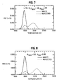
- the normalized PSDs of spectral radiation intensity at 1000 nm for the three open fires are shown in Fig. 3.
- the normalized PSDs obtained from reflected and direct radiation are shown in the top (A) and bottom panels (B) respectively of Fig. 3.
- the PDFs of apparent source temperatures obtained from direct radiation for the smoldering cotton fire 8 varies from 900 to 1100 K, and that for the smoldering wood fire 9 varies from 700 to 900 K, as shown in the bottom panel of Fig. 4.
- the PDF of apparent source temperatures obtained using reflected radiation from the smoldering cotton fire 8 is approximately 200 K lower.
- the PDF is not continuous. This is because the reflected intensities incident on the NIR fire detector from the smoldering cotton fire 8 are very low. For the smoldering wood fire 9, the reflected intensities were below the detection threshold of the NIR fire detector 4.
- the normalized PSDs of spectral radiation intensities at 1000 nm for the two smoldering fires are shown in Fig. 5.
- the intensities obtained from the direct view of the smoldering wood fire 9 and from the reflected view of the cotton fire 8a are barely above the noise level, and therefore could not be identified by the near infrared fire detector 4 as valid fire signals.
- TF3 standard test fire
- CEN "Components of Automatic Fire Detection Systems: Fire Sensitivity Test.” Part 9, European Committee for Standardization , Brussels (1982).
- CEN "Components of Automatic Fire Detection Systems: Fire Sensitivity Test.” Part 9, European Committee for Standardization , Brussels (1982).
- CEN "Components of Automatic Fire Detection Systems: Fire Sensitivity Test.” Part 9, European Committee for Standardization , Brussels (1982).
- an alternative standard test for smoldering wood would be more appropriate.
- the intensities obtained from reflected radiation at 900 and 1000 nm are an order of magnitude lower than those obtained from direct radiation.
- a three dimensional rectangular enclosure 60 of length L, and width and height a has a heptane pool fire 5 at one end.
- the angular distribution of spectral radiation intensities emanating from a standard heptane pool fire 5 was measured and used as a radiation source for the simulations.
- a detector 4 is placed at the other end as shown in Fig. 6. Part of the radiation emitted by the blackbody is absorbed by the walls 60a of the enclosure 60, and the remainder reflected. The absorptivity of the walls 60a also changes with wavelength. The reflectivity of the walls 60a of the enclosure 60 has both a specular and diffuse component.
- the effect of the interaction of the photons with the walls 60a of the enclosure 60 on the temperatures estimated by the NIR fire detector 4 are calculated using a photon tracing algorithm as set forth in detail in "Radiative Heat Transfer Inside a Cylindrical Enclosure with Nonparticipating Media Using A Deterministic Statistical Method," Proceedings of the ASME Heat Transfer Division, HTD-Vol 332, PP. 145-152, ASME, New York.
- photons of different wavelengths representing the heptane fires 5 are launched into the enclosure 60 at various angles, also representing the heptane fires 5.
- An individual photon strikes a surface 60a of the enclosure 60 depending on this angle of launch.
- the photon is either absorbed or reflected based on a probability assigned by the surface reflectivity to each of these events.
- the photon may be reflected at the same angle as that of the incidence or may be reflected at a random angle also based on probabilities assigned by the surface reflection properties.
- the photons incident on the detector 4 are absorbed and contribute to the radiation intensity signal. In the calculation procedure, over 10,000 photons are launched and the intensity measured by the detector 4 is equated to the fraction of these photons hitting the detector 4 times the intensity of the fire 5.
- the PDFs of apparent source temperatures for an axisymmetric enclosure (not shown) with and without considering reflections from the walls of the enclosure are depicted in Fig. 7.
- the aspect (length to radius) ratio of the enclosure was 3.
- the walls of the enclosure were assumed to have reflectivities of 0.8 and 0.88 for the 1000 nm and 900 nm radiation respectively.
- the specularity of the reflection was assumed to be 0.4.
- the PDFs of source temperatures with and without considering the reflected photons from the walls of the enclosure are shown by the dotted and solid line in Fig. 7 respectively.
- a fraction of photons was directly incident on the detector 4 without undergoing any reflections from the wall. Therefore, the apparent source temperatures obtained from these direct photons were not changed.
- the effect of the reflections is to increase the apparent source temperatures inferred by the NIR fire detector 4 since the longer wavelength photons are preferentially absorbed. Therefore, the PDF of apparent source temperatures obtained taking the reflected photons into account has a bimodal behavior.
- the NIR fire detector 4 could successfully discriminate the fires from background radiation, since most of the temperatures are still within 800 to 2500 K.
- the PSDs of intensities do not vary with reflections in the simulation (as well as in ideal experiments) since the time taken by the photons to undergo multiple reflections with a wall 60a is much lower than the smallest time scales present in the flow.
- Fig. 8 The effect of wall 60a reflections on the PDF of apparent source temperatures for the rectangular enclosure 60 is shown in Fig. 8. Similar to the axisymmemtric case, the walls 60a of the enclosure 60 were assumed to absorb 20% of the photons at 1000 nm, and 12% of the photons at 900 nm. The specularity of the reflectivity was also set at 0.4. Similar to the results of the axisymmetric enclosure, the preferential absorption of the longer wavelengths leads to an increase in the apparent source temperatures (shown by the dotted line in Fig. 8). In addition, the combination of direct and reflected photons result in a bimodal PDF for the apparent source temperatures.
- a near-infrared fire detector which operates on the principle of apparent source temperatures obtained from spectral radiation intensity measurements at two near-infrared wavelengths has been described in theory.
- a detection algorithm is provided that is capable of indicating the presence of fire in the vicinity of the detector based on a probability density function and power spectral density analysis of apparent source temperatures.
- the novel detector is also effective for detecting many fires that are not in its direct view and that may occur in the presence of interference from natural and artificial sources.
- detector 900 may provide output to a selected alarm device (901) including one that may play audio instructions, an electronic security system, an automated telephone, or to a fire suppression system such as sprinklers.
- the fire suppression systems may also include automated actuation devices such as squib actuated bottles (not shown).
- the sensitivity and range of the device, background tolerances, and even the process for detection and false signal discrimination in the two applications can be customized by programming.
- the detector 900 includes a flame detection unit 90 and a smoke detection unit 99.
- the flame detection unit 90 has a wide view angle (at least 270 degrees and can approach 360 degrees) afforded by fiber optic doublets 91 mounted on multiple viewing faces 92 of a viewing head 93.
- Each member of the fiber optic doublet 91 carries radiation from the room (not shown) into a multi-fiber connector 94.
- the multi-fiber connector 94 has a reflective inner surface or a receptacle (not shown) to direct all incoming radiation carried into it on to the near infrared photo-detectors 95a, 95b.
- the photo-detectors 95a, 95b are equipped with narrow band optical filters (not shown) at two closely spaced wavelengths in the near infrared part of the spectrum (700 to 1000 nm wavelengths).
- the photo-detectors 95a, 95b generate electrical signals corresponding to the incident near infrared radiation intensities. These signals are digitized by an analog to digital conversion chip 97 and input to a microprocessor 98.
- the microprocessor 98 contains stored information concerning calibration constants of the detectors, optical fibers, and filters and converts the digital input into digital near-infrared light intensity values.
- the radiation intensity I ⁇ 1 C ⁇ 1 V 1 where V 1 is the voltage on the first photo-diode and C ⁇ 1 is a calibration constant for the combination of optical filters, diodes and electronic amplification circuits.
- the radiation intensity I ⁇ 2 C ⁇ 2 V 2 where V 2 is the voltage on the second photo-diode and C 12 is a calibration constant for the combination of optical filters, diodes and electronic amplification circuits.
- C ⁇ 1 and C ⁇ 2 which are stored in memory 98a. If at least 40% (or some number between 1% and 99%) of the source temperatures obtained from the 128 points are between 700 and 2500 K, then a frequency analysis is conducted as explained below. The near infrared intensities at the two wavelengths are sampled for a specific time-period and a series of digital radiation temperatures of the incident radiation field are calculated.
- a record of the background intensities and power spectral densities is continuously generated and updated by the microprocessor 98 and compared with stored information retrieved from store 98a concerning corresponding values when radiation from a flame is incident on any one or more of the fiber doublets 91.
- the average of the background intensities are also stored for ten seconds and at any particular sampling period of 1 sec, the intensities are stored after subtracting the average intensity obtained from 10 seconds before the current period. This allows a dynamic background intensity correction.
- the biggest advantage of this scheme is the variation in ambient radiation (such as bright sunny days or dark nights or brightly lit room etc.), does not affect the sensitivity of the detector 4 in any means.
- the power spectral density describes how the variance of a random process is distributed with frequency.
- E(f) is the spectrum function for the signal I ⁇ (t), divided by the mean square deviation of I ⁇ .
- This spectrum function can be obtained by standard FFT, commercial FFT subroutines such as ISML.
- S(f) is the spectrum function for white noise, which when sampled at a frequency of M (and low pass filtered at M/2), has a uniform value 2/M between 0 and M/2 and is 0 at other frequencies.
- I' is the fluctuation of I 1 from its mean value obtained from all data points.
- the normalized PSD at any frequency represents the ratio of the total energy of the signal below that frequency in comparison with a white noise source sampled with the same temporal resolution.
- the area under the power spectral density curve for any frequency range is proportional to the energy of the instantaneous fluctuations of the signal from its mean value. Fire is detected if the noise normalized area under the frequency spectrum curve is greater than 1.5 at a frequency (f) which could be from 5 to 20 Hz.
- E R ratioed power spectral density
- Power spectral density of noise normalizes the incident power spectral density before comparison.
- the microprocessor therefore knows the probability density function signatures and noise normalized power spectral density signatures of standard fires in the first instance.
- the microprocessor 98 evaluates a detected flame based on incident radiation therefrom.
- the distance of a flame from the detector 900 does not restrict the detection, because source temperature rather than the intensity of the source is the detection criterion.
- This noise normalized power spectral density check allows the invention to discriminate between a non-fire radiation source and a fire.
- the present invention contemplates separate smoke detection channels.
- s K V where K is a calibration constant (such as using a known optical arrangement or a standard reference material such as polystyrene bead or alcohol droplets from a monodisperse generator (not shown)) and V is the voltage on the scattering detector 1302.
- Detector 1302 can either have a wide angle or a narrow angle view, as desired.
- Parameter (s/t) is the scattering to extinction ratio and provides information on the optical characteristics of soot produced from fires. Therefore if this parameter falls within 0.2 and 0.3, then the scattering to extinction ratio is typical of soot formed by hydro-carbon combustion. If this falls within 0.7 and 0.9, then it is representative of particulates formed from the combustion of silicone fuels.
- the smoke detection cell 99 responds to light absorption or scattering of impinging light on the detector as discussed below.
- light-sensing optical fiber 99c receives light-pulses from light emitting diode 105 (Figs. 9, 10) serving as a scattered light detector reference.
- the pulses are at a very high frequency to avoid any interference with the noise-normalized power spectral density of radiation monitored by the flame sensor 90.
- a portion of these light pulses is scattered when there is smoke entering into chamber 99 through apertures 102B (Fig. 9a).
- the light intensity level received by the scatter channel fiber 99a increases. This scattered light information is relayed to the photodiodes 95a or 95b by optical fiber 99a.
- light sensing optical fibers 99b receive light pulses from the LED 105 (Fig. 10), as light absorption signals. A portion of these light pulses are absorbed when there is smoke in chamber 99. Pulses emanating from fiber 99a, 99b are amplified by op/amps 104a and routed to the microprocessor 98. The microprocessor 98 makes a comparison of the scattered light sensed by the fibers 99a. and the absorbed light sensed by fibers 99b at a high frequency without interfering with the low frequency flame detection channels described earlier. The microprocessor 98 is thus enabled to determine if smoke is present.
- the present invention contemplates usage of inexpensive, readily available acrylic fiber optic (such as that manufactured by 3M Corporation) to serve as light sensing fibers 99a-c. View angles approaching 360 degrees utilizing optic fiber can be attained.
- the microprocessor 98 compares the intensities on the scattering and absorption channels to estimate the size and concentration of associated particulate. Such a check eliminates false alarms by dust and smog.
- the presence of smoke by itself could be used to sound an alarm and/or send the appropriate output signal via a sounding device 100 or to an external alarm 901. Presence of smoke in addition to that of flame is the alarm criterion in some areas (open kitchen, room with a fireplace), where a flame is expected. Any logical combination of the results of the flame plus smoke detection scheme in accordance with the present invention can be programmed into the microprocessor depending on the application, as one of ordinary skill can readily appreciate.
- the detector unit 900 can be housed in a suitable box 101 with a cover 102 (Figs. 9a, 9b, 10).
- An indicator 96 (Figs. 9, 9a, b) can be provided to show when the detector 900 is operational.
- the indicator 96 can take the form of a panel light, LED. or similar apparatus as one of ordinary skill can appreciate.
- the smoke detection and discrimination method is enabled because fire-generated smoke has unique particulate size distribution and optical properties that can be examined using near-infrared optics.
- the flame detection method is enabled due to the fact that common household and automotive fires have two unique characteristics: (1) source temperature probability distribution function, and (2) noise-normalized power spectral density.
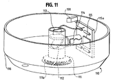
- Fig. 11 shows an alternate embodiment of the invention that does not rely on the use of fiber optics for light transmission.
- This embodiment 110 uses a fish-eye lens 111 and a beam splitter 112 instead of the fiber optics hereinbefore described.
- a fish eyes lens any number of wide angle, ultra wide angle or similar optic apparatus could be utilized.
- the present invention therefore need not be restricted to an embodiment that uses fiber optics.
- the embodiment of Fig. 11 includes a suitable housing 116 carrying a printed circuit board 115 with a digital signal processor (DSP) 115 operatively connected to a first detector 113 for a first wavelength, and a second detector 114 for a second wavelength.
- DSP digital signal processor
- the DSP 115 could have an inboard A/D connector or an outboard A/D connector, as one of ordinary skill can easily contemplate.
Landscapes
- Business, Economics & Management (AREA)
- Emergency Management (AREA)
- Physics & Mathematics (AREA)
- General Physics & Mathematics (AREA)
- Fire-Detection Mechanisms (AREA)
- Investigating Or Analysing Materials By Optical Means (AREA)
Claims (18)
- Ein Rauch- und Flammendetektor (4, 4a, 110, 900, 1304), der Folgendes beinhaltet:erste und zweite Photodetektoren (95a, 95b, 113, 114), die in einem nahen Infrarotspektrum einsatzfähig sind;erste und zweite optische Filtermittel (5b, 5c), die mit den besagten ersten beziehungsweise zweiten Photodetektoren (95a, 95b, 113, 114) gekoppelt sind;einen analog zu digital (A/D) Konverter (6a, 97), der betrieblich mit den besagten Photodetektoren (95a, 95b, 113, 114) gekoppelt ist;einen Mikroprozessor (98), der betrieblich mit dem besagten A/D-Konverter (6a, 97) gekoppelt ist;ein Datenspeichermittel (98a), um Informationen zu speichern, wobei das besagte Datenspeichermittel (98a) mit dem besagten Mikroprozessor (98) und dem besagten A/D-Konverter (6a, 97) gekoppelt ist;erste und zweite Photodioden (95a, 95b, 113, 114);einen digital zu analog (D/A) Konverter (6a, 97), der betrieblich mit den besagten Photodioden (95a, 95b, 113, 114) gekoppelt ist;den besagten Mikroprozessor (98), der betrieblich mit den besagten ersten und zweiten Photodioden (95a, 95b, 113, 114) und dem besagten D/A-Konverter (6a, 97) gekoppelt ist;eine Vielzahl von Lichtmesselementen (99a, 99b, 99c), um damit Licht von wenigsten einer der besagten ersten und zweiten Dioden (95a, 95b, 113, 114) aufzunehmen, und das aufgenommene Licht an den besagten Mikroprozessor (98) weiterzuleiten;wenigstens eines der besagten Lichtmesselemente (99a, 99b, 99c), das ein Detektionsmittel (99b) für die Lichtabsorption beinhaltet, um für den besagten Mikroprozessor (98) Informationen, die mit der Intensität des aufgenommenen Lichts zusammenhängen, bereitzustellen;wenigstens ein anderes der besagten Lichtmesselemente (99a, 99b, 99c), das ein Detektionsmittel (99a) für Streulicht beinhaltet, welches an den besagten Mikroprozessor (98) gekoppelt ist, um damit Streulicht aufzunehmen, und das aufgenommene Streulicht an den besagten Mikroprozessor (98) weiterzuleiten; was dadurch gekennzeichnet ist, dassder besagte Mikroprozessor (98) des Weiteren Mittel für die Umwandlung des Lichtintensitätwertes und für die Stichprobenprüfung beinhaltet, um die von dem besagten A/D-Konverter (6a, 97) eingegebene Lichtintensität in Werte in einem Bereich in einem nahen Infrarotspektrums umzuwandeln, und die besagten Werte für einen vorher festgesetzten Zeitraum als Stichproben zu prüfen;das besagte Datenspeichermittel (98a) die Intensitätswerte, die aus einer vorher festgesetzten Stichprobenprüfperiode erhalten wurden, speichert, und der besagte Detektor (4, 4a, 110, 900, 1304) die besagten gespeicherten Werte dazu verwendet, die Temperatur-PDF und die an das Grundrauschen normalisierte, spektrale Leistungsdichte zu bestimmen;jeder der besagten Photodetektoren (95a, 95b, 113, 114), Photodioden (95a, 95b, 113, 114), Lichtmesselemente (99a, 99b, 99c) und optischen Filtermittel (5a, 5b) eine Eichkonstante beinhalten; undworin ein ausgegebenes, an das Grundrauschen normalisiertes Verhältnis EN (f) berechnet wird, unter Verwendung von:

worin E(f) die spektrale Leistungsdichte der Spannung, der Intensität oder der Temperatur ist, und S(f) die spektrale Leistungsdichte des Zufallsrauschens ist, welches für eine festgelegte Häufigkeit der Stichprobenprüfungen konstant ist. - Der Rauch- und Flammendetektor (4, 4a, 110, 900, 1304) aus Anspruch 1, worin wenigstens eines der besagten Detektionsmittel (99b) für die Lichtabsorption und der besagten Detektionsmittel (99a) für Streulicht eine optische Linse (111) beinhaltet.
- Der Rauch- und Flammendetektor (4, 4a, 110, 900, 1304) aus Anspruch 1, worin wenigstens eines der besagten Lichtmesselemente (99a, 99b, 99c) aus optischer Faser besteht.
- Der Rauch- und Flammendetektor (4, 4a, 110, 900, 1304) aus Anspruch 3, worin die besagte optische Faser (99a, 99b, 99c) aus Kunststoff besteht.
- Der Rauch- und Flammendetektor (4, 4a, 110, 900, 1304) aus Anspruch 1, worin das besagte Detektionsmittel (99a) für Streulicht aus optischer Faser besteht.
- Der Rauch- und Flammendetektor (4, 4a, 110, 900, 1304) aus Anspruch 1, worin das besagte Detektionsmittel (99b) für die Lichtabsorption aus optischer Faser besteht.
- Der Rauch- und Flammendetektor (4, 4a, 110, 900, 1304) aus Anspruch 5, worin die besagte optische Faser (99a, 99b, 99c) aus Kunststoff beseht.
- Der Rauch- und Flammendetektor (4, 4a, 110, 900, 1304) aus Anspruch 1, worin das besagte Datenspeichermittel (98a) Informationen beinhaltet, welche mit den besagten Eichkonstanten zusammenhängen.
- Der Rauch- und Flammendetektor (4, 4a, 110, 900, 1304) aus Anspruch 1, worin der besagte Mikroprozessor (98), unter Verwendung der besagten gespeicherten Werte für die Intensität ein Einstrahlungsfeld in Übereinstimmung mit einer detektierten Strahlungsintensität Iλ1 = C11 V1 berechnet, wobei V1 die Spannung an der ersten Photodiode (95a, 95b, 113, 114) ist, und C11 die besagte Eichkonstante ist, und worin eine detektierte Strahlungsintensität Iλ2 = C12 V2 ist, wobei V2 die Spannung an der zweiten Photodiode (95a, 95b, 113, 114) ist, und C12 eine Eichkonstante ist.
- Der Rauch- und Flammendetektor (4, 4a, 110, 900, 1304) aus Anspruch 9, worin der besagte Mikroprozessor (98) über eine Vielzahl von Stichprobenprüfpunkten eine Wahrscheinlichkeitsdichte für die Temperatur einer Flammenquelle bestimmt, in Übereinstimmung mit
T = KIλ1/Iλ2 für jeden der besagten Stichprobenprüfpunkte,
wobei T die Temperatur ist, K eine Eichkonstante ist, und Iλ1 und Iλ2 erfasste Intensitäten repräsentieren. - Der Rauch- und Flammendetektor (4, 4a, 110, 900, 1304) aus Anspruch 10, worin die besagte bestimmte Temperatur in dem besagten Datenspeichermittel (98a) gespeichert wird.
- Der Rauch- und Flammendetektor (4, 4a, 110, 900, 1304) aus Anspruch 10, worin wenigstens einer der besagten Stichprobenprüfpunkte für die Temperatur in einen Temperaturbereich fällt, der ungefähr zwischen 700K und 2500K liegt.
- Der Rauch- und Flammendetektor (4, 4a, 110, 900, 1304) aus Anspruch 1, beinhaltet des Weiteren einen Tiefpassfilter (5b, 5c, 104a), wobei das besagte weiße Rauschen bei einer Frequenz von M/2 tiefpassgefiltert wird.
- Der Rauch- und Flammendetektor (4, 4a, 110, 900, 1304) aus Anspruch 13, worin das besagte tiefpassgefilterte, weiße Rauschen einen einheitlichen Wert 2/M zwischen Null und M/2 beinhaltet, und worin der besagte Wert bei anderen Frequenzen ungefähr gleich Null ist.
- Der Rauch- und Flammendetektor (4, 4a, 110, 900, 1304) aus Anspruch 1, worin ein festgesetzter Level von EN(f) dazu verwendet wird, das Vorhandensein eines Feuers anzuzeigen.
- Der Rauch- und Flammendetektor (4, 4a, 110, 900, 1304) aus Anspruch 1, worin aus einem Verhältnis die spektrale Leistungsdichte ER(f) berechnet wird, in Übereinstimmung mit

worin f1L eine erste untere Frequenz ist, die von 0 bis 50 Hz reicht, f1H eine erste höhere Frequenz ist, die größer als f1L ist, f2L eine zweite tiefere Frequenz ist, die von 0 bis 50 Hz reicht, und f2H eine zweite höhere Frequenz ist, die größer als f2L ist. - Der Rauch- und Flammendetektor (4, 4a, 110, 900, 1304) aus Anspruch 16, worin der Wert von ER(f) das Vorhandensein eines Feuers anzeigt.
- Ein Verfahren um eine Flamme zu detektieren, welches folgende Schritte beinhaltet:Erfassen eines Levels von natürlicher Strahlung;Detektieren von wenigstens einer Strahlungsquelle, die eine Frequenz im nahen Infrarotspektrum hat;Stichprobenprüfung der detektierten Strahlung über einen vorher festgesetzten Zeitraum; was dadurch gekennzeichnet ist, dass das Verfahren die folgenden Schritte enthält:Berechnen einer Reihe von Strahlungstemperaturen in Echtzeit, um ein einfallendes Strahlungsfeld zu bestimmen;Erzeugung einer Wahrscheinlichkeitsdichtefunktion (PDF) für einen von einem einfallenden Strahlungsfeld, einer Temperatur und einem Spannungslevels;Berechnen einer Leistungsdichte für die besagte PDF;Vergleichen der erfassten, natürlichen Strahlung mit der berechneten Leistungsdichte, um einen Wert zu liefern; undBereitstellen eines Alarms, der es anzeigt, wenn der besagte Wert einen vorher festgesetzten Level übersteigt.
Applications Claiming Priority (3)
| Application Number | Priority Date | Filing Date | Title |
|---|---|---|---|
| US9054 | 1993-01-26 | ||
| US09/009,054 US6111511A (en) | 1998-01-20 | 1998-01-20 | Flame and smoke detector |
| PCT/US1999/001071 WO1999036892A1 (en) | 1998-01-20 | 1999-01-19 | Flame and smoke detector |
Publications (3)
| Publication Number | Publication Date |
|---|---|
| EP1057149A1 EP1057149A1 (de) | 2000-12-06 |
| EP1057149A4 EP1057149A4 (de) | 2004-05-19 |
| EP1057149B1 true EP1057149B1 (de) | 2006-05-31 |
Family
ID=21735322
Family Applications (1)
| Application Number | Title | Priority Date | Filing Date |
|---|---|---|---|
| EP99903175A Expired - Lifetime EP1057149B1 (de) | 1998-01-20 | 1999-01-19 | Flamm- und rauchdetektion |
Country Status (7)
| Country | Link |
|---|---|
| US (1) | US6111511A (de) |
| EP (1) | EP1057149B1 (de) |
| AT (1) | ATE328337T1 (de) |
| AU (1) | AU758197B2 (de) |
| CA (1) | CA2318110C (de) |
| DE (1) | DE69931610D1 (de) |
| WO (1) | WO1999036892A1 (de) |
Cited By (3)
| Publication number | Priority date | Publication date | Assignee | Title |
|---|---|---|---|---|
| EP2571001B1 (de) * | 2011-09-16 | 2017-04-19 | Honeywell International Inc. | Flammendetektor mit optischer Erfassung |
| CN106897720A (zh) * | 2017-01-11 | 2017-06-27 | 济南中维世纪科技有限公司 | 一种基于视频分析的烟火检测方法及装置 |
| EP4682850A1 (de) * | 2024-07-19 | 2026-01-21 | Life Safety Distribution GmbH | Optisches zubehör, system und verfahren zum trainieren eines flammendetektors |
Families Citing this family (43)
| Publication number | Priority date | Publication date | Assignee | Title |
|---|---|---|---|---|
| US20030010920A1 (en) * | 1999-09-01 | 2003-01-16 | Purdue Research Foundations | Wide angle viewing device |
| FR2805048B1 (fr) * | 2000-02-16 | 2002-05-03 | Algade | Ensemble et procede de mesure de rayonnement ionisant avec correction de bruit de fond |
| US6184792B1 (en) * | 2000-04-19 | 2001-02-06 | George Privalov | Early fire detection method and apparatus |
| US6545608B1 (en) * | 2000-06-23 | 2003-04-08 | Michael G. Kaufman | Smoking rules enforcement apparatus |
| US7066273B2 (en) * | 2001-04-06 | 2006-06-27 | Benjamin Tan | Apparatus and methods for sensing of fire and directed fire suppression |
| US6967582B2 (en) * | 2002-09-19 | 2005-11-22 | Honeywell International Inc. | Detector with ambient photon sensor and other sensors |
| US7068177B2 (en) * | 2002-09-19 | 2006-06-27 | Honeywell International, Inc. | Multi-sensor device and methods for fire detection |
| DE10350277A1 (de) * | 2003-10-28 | 2005-06-09 | Fraunhofer-Gesellschaft zur Förderung der angewandten Forschung e.V. | Verfahren und Vorrichtung zum Überwachen von Räumen |
| US20050128093A1 (en) * | 2003-12-16 | 2005-06-16 | Genova James J. | Self-protected fire-sensing alarm apparatus and method |
| US20050252663A1 (en) | 2004-05-17 | 2005-11-17 | Olson Mark P | Fiber-optic based automatic fire-suppression controller |
| US7142107B2 (en) | 2004-05-27 | 2006-11-28 | Lawrence Kates | Wireless sensor unit |
| US7289032B2 (en) * | 2005-02-24 | 2007-10-30 | Alstom Technology Ltd | Intelligent flame scanner |
| EP1905200A1 (de) | 2005-07-01 | 2008-04-02 | Terahop Networks, Inc. | Nichtdeterministisches und deterministisches netzwerk-routing |
| ATE394764T1 (de) * | 2005-11-04 | 2008-05-15 | Siemens Ag | Kombinierter streulicht- und extinktionsbrandmelder |
| US20090014657A1 (en) * | 2007-05-01 | 2009-01-15 | Honeywell International Inc. | Infrared fire detection system |
| US7746236B2 (en) * | 2007-05-01 | 2010-06-29 | Honeywell International Inc. | Fire detection system and method |
| WO2009151877A2 (en) | 2008-05-16 | 2009-12-17 | Terahop Networks, Inc. | Systems and apparatus for securing a container |
| US20100172471A1 (en) * | 2009-01-05 | 2010-07-08 | Sivathanu Yudaya R | Method and apparatus for characterizing flame and spray structure in windowless chambers |
| US9459216B2 (en) | 2009-01-05 | 2016-10-04 | En'urga, Inc. | Method for characterizing flame and spray structures in windowless chambers |
| US8754775B2 (en) | 2009-03-20 | 2014-06-17 | Nest Labs, Inc. | Use of optical reflectance proximity detector for nuisance mitigation in smoke alarms |
| US8199029B2 (en) * | 2009-06-22 | 2012-06-12 | Kidde Technologies, Inc. | Combined smoke detector and lighting unit |
| US8346500B2 (en) * | 2010-09-17 | 2013-01-01 | Chang Sung Ace Co., Ltd. | Self check-type flame detector |
| US8899097B2 (en) * | 2011-10-18 | 2014-12-02 | The Boeing Company | Airborne impurities detection |
| US9046411B2 (en) * | 2011-11-14 | 2015-06-02 | General Electric Company | Optical sensor system for a gas turbine engine and method of operating the same |
| US8952821B2 (en) | 2012-04-29 | 2015-02-10 | Valor Fire Safety, Llc | Smoke detector utilizing ambient-light sensor, external sampling volume, and internally reflected light |
| US9140646B2 (en) | 2012-04-29 | 2015-09-22 | Valor Fire Safety, Llc | Smoke detector with external sampling volume using two different wavelengths and ambient light detection for measurement correction |
| US8907802B2 (en) | 2012-04-29 | 2014-12-09 | Valor Fire Safety, Llc | Smoke detector with external sampling volume and ambient light rejection |
| US9396637B2 (en) | 2012-07-13 | 2016-07-19 | Walter Kidde Portable Equipment, Inc | Photoelectric smoke detector with drift compensation |
| EP2688274A1 (de) * | 2012-07-18 | 2014-01-22 | Siemens Aktiengesellschaft | Mobiles Kommunikationsendgerät mit einer darauf ausführbaren Brandmelder-Applikation sowie eine von einem Online-Internet-Verkaufsportal herunterladbare Brandmelder-Applikation |
| US9208676B2 (en) | 2013-03-14 | 2015-12-08 | Google Inc. | Devices, methods, and associated information processing for security in a smart-sensored home |
| CN105849787B (zh) | 2013-10-30 | 2019-02-15 | 瓦洛尔消防安全有限责任公司 | 具有外部采样体积和环境光抑制的烟雾探测器 |
| GB2533262B (en) * | 2014-11-06 | 2019-06-05 | Plumis Ltd | Wall-mountable spray head unit |
| CN105744132B (zh) * | 2016-03-23 | 2020-01-03 | 捷开通讯(深圳)有限公司 | 全景图像拍摄的光学镜头配件 |
| WO2018013514A1 (en) | 2016-07-11 | 2018-01-18 | Carrier Corporation | Flame scanner with photodiode |
| US10378957B2 (en) * | 2016-09-13 | 2019-08-13 | Safe-Fire Technology LLC | System and method for measuring coal burner flame temperature profile using optical device |
| EP3539108B1 (de) * | 2016-11-11 | 2020-08-12 | Carrier Corporation | Auf hochempfindlicher faseroptik basierende detektion |
| EP3539103A1 (de) | 2016-11-11 | 2019-09-18 | Carrier Corporation | Auf hochempfindlicher faseroptik basierende detektion |
| EP3539109B8 (de) | 2016-11-11 | 2024-02-14 | Carrier Corporation | Auf hochempfindlicher faseroptik basierende detektion |
| CA3043500A1 (en) | 2016-11-11 | 2018-05-17 | Carrier Corporation | High sensitivity fiber optic based detection |
| US10852202B2 (en) * | 2016-11-11 | 2020-12-01 | Kidde Technologies, Inc. | High sensitivity fiber optic based detection |
| EP3539105B1 (de) | 2016-11-11 | 2024-09-11 | Carrier Corporation | Auf hochempfindlicher faseroptik basierende detektion |
| EP3803819B1 (de) * | 2018-05-31 | 2024-05-01 | Autronica Fire & Security AS | Leiterplatte für rauchmelder |
| CN111368445B (zh) * | 2020-03-09 | 2023-06-30 | 中国石油天然气集团有限公司 | 一种基于天然气热辐射的安全距离确定方法及系统 |
Family Cites Families (17)
| Publication number | Priority date | Publication date | Assignee | Title |
|---|---|---|---|---|
| CH558577A (de) * | 1973-09-25 | 1975-01-31 | Cerberus Ag | Verfahren zur flammen-detektion und vorrichtung zur durchfuehrung dieses verfahrens. |
| US3983548A (en) * | 1975-02-19 | 1976-09-28 | Tufts Howard L | Fire detection system |
| GB2044504B (en) * | 1979-03-17 | 1983-04-20 | Hochiki Co | Count discriminating fire detector |
| US4533834A (en) * | 1982-12-02 | 1985-08-06 | The United States Of America As Represented By The Secretary Of The Army | Optical fire detection system responsive to spectral content and flicker frequency |
| FI854809A7 (fi) * | 1984-12-18 | 1986-06-19 | Hochiki Co | Branddetektor som baserar sig pao minskat ljus. |
| GB2174002B (en) * | 1985-04-23 | 1988-12-21 | Tekken Constr Co | Automatic fire extinguisher with infrared ray responsive type fire detector |
| US4857895A (en) * | 1987-08-31 | 1989-08-15 | Kaprelian Edward K | Combined scatter and light obscuration smoke detector |
| US5107128A (en) * | 1989-05-05 | 1992-04-21 | Saskatchewan Power Corporation | Method and apparatus for detecting flame with adjustable optical coupling |
| US5073769A (en) * | 1990-10-31 | 1991-12-17 | Honeywell Inc. | Flame detector using a discrete fourier transform to process amplitude samples from a flame signal |
| US5245496A (en) * | 1991-08-16 | 1993-09-14 | Kim Nam H | Self-programming non-invasive motor overload prevention system |
| US5400014A (en) * | 1993-07-12 | 1995-03-21 | Detection Systems, Inc. | Smoke detector with dark chamber |
| JP3330438B2 (ja) * | 1993-12-16 | 2002-09-30 | 能美防災株式会社 | 煙感知器およびその調整装置 |
| US5751216A (en) * | 1994-09-27 | 1998-05-12 | Hochiki Kabushiki Kaisha | Projected beam-type smoke detector and receiving unit |
| US5625342A (en) * | 1995-11-06 | 1997-04-29 | The United States Of America As Represented By The Administrator Of The National Aeronautics And Space Administration | Plural-wavelength flame detector that discriminates between direct and reflected radiation |
| US5691699A (en) * | 1996-02-08 | 1997-11-25 | Detection Systems, Inc. | Security detector with optical data transmitter |
| US5705988A (en) * | 1996-07-08 | 1998-01-06 | Detection Systems, Inc. | Photoelectric smoke detector with count based A/D and D/A converter |
| US5889468A (en) * | 1997-11-10 | 1999-03-30 | Banga; William Robert | Extra security smoke alarm system |
-
1998
- 1998-01-20 US US09/009,054 patent/US6111511A/en not_active Expired - Fee Related
-
1999
- 1999-01-19 WO PCT/US1999/001071 patent/WO1999036892A1/en not_active Ceased
- 1999-01-19 AT AT99903175T patent/ATE328337T1/de not_active IP Right Cessation
- 1999-01-19 DE DE69931610T patent/DE69931610D1/de not_active Expired - Lifetime
- 1999-01-19 AU AU23258/99A patent/AU758197B2/en not_active Ceased
- 1999-01-19 CA CA002318110A patent/CA2318110C/en not_active Expired - Fee Related
- 1999-01-19 EP EP99903175A patent/EP1057149B1/de not_active Expired - Lifetime
Cited By (3)
| Publication number | Priority date | Publication date | Assignee | Title |
|---|---|---|---|---|
| EP2571001B1 (de) * | 2011-09-16 | 2017-04-19 | Honeywell International Inc. | Flammendetektor mit optischer Erfassung |
| CN106897720A (zh) * | 2017-01-11 | 2017-06-27 | 济南中维世纪科技有限公司 | 一种基于视频分析的烟火检测方法及装置 |
| EP4682850A1 (de) * | 2024-07-19 | 2026-01-21 | Life Safety Distribution GmbH | Optisches zubehör, system und verfahren zum trainieren eines flammendetektors |
Also Published As
| Publication number | Publication date |
|---|---|
| EP1057149A4 (de) | 2004-05-19 |
| AU758197B2 (en) | 2003-03-20 |
| WO1999036892A1 (en) | 1999-07-22 |
| AU2325899A (en) | 1999-08-02 |
| ATE328337T1 (de) | 2006-06-15 |
| EP1057149A1 (de) | 2000-12-06 |
| US6111511A (en) | 2000-08-29 |
| DE69931610D1 (de) | 2006-07-06 |
| CA2318110A1 (en) | 1999-07-22 |
| CA2318110C (en) | 2002-07-09 |
Similar Documents
| Publication | Publication Date | Title |
|---|---|---|
| US6111511A (en) | Flame and smoke detector | |
| US5966077A (en) | Fire detector | |
| EP2112639B1 (de) | Verbesserung(en) in Zusammenhang mit Teilchendetektoren | |
| US7551277B2 (en) | Particle monitors and method(s) therefor | |
| US7760102B2 (en) | Fire or smoke detector with high false alarm rejection performance | |
| US6150935A (en) | Fire alarm system with discrimination between smoke and non-smoke phenomena | |
| US5767776A (en) | Fire detector | |
| US6166647A (en) | Fire detector | |
| WO1996041318A1 (en) | Multi-signature fire detector | |
| Heskestad et al. | Fire detection using cross-correlations of sensor signals | |
| TWI861125B (zh) | 微粒感測器 | |
| AU703685B2 (en) | Method of detecting a flame and flame detector for carrying out the method | |
| Sivathanu et al. | Fire detection using time series analysis of source temperatures | |
| Kim et al. | Characterization of spectral radiation intensities from standard test fires for fire detection | |
| CN119007378A (zh) | 基于颗粒粒径、形状及折射率联合特征的火灾烟雾探测器 | |
| MXPA00007211A (es) | Detector de humo y flama | |
| Meacham et al. | Characterization of smoke from smoldering combustion for the evaluation of light scattering type smoke detector response | |
| Serio et al. | Fourier Transform Infrared Diagnostics for Improved Fire Detection Systems | |
| AU2007203107A9 (en) | Improvement(s) related to particle monitors and method(s) therefor | |
| CA2598745A1 (en) | Improvement(s) related to particle monitors and method(s) therefor | |
| Jang et al. | Classification of Fire Smoke Particles and Nuisance Aerosols Using Scattering Light Distribution Characteristics | |
| HK1099395B (en) | Improvement(s) related to particle monitors and method(s) therefor | |
| AU3413089A (en) | Fluid pollution monitor | |
| HK1115187A (en) | A chamber configuration for a particle detector and a method of enabling fluid to flow through a particle detection zone |
Legal Events
| Date | Code | Title | Description |
|---|---|---|---|
| PUAI | Public reference made under article 153(3) epc to a published international application that has entered the european phase |
Free format text: ORIGINAL CODE: 0009012 |
|
| 17P | Request for examination filed |
Effective date: 20000810 |
|
| AK | Designated contracting states |
Kind code of ref document: A1 Designated state(s): AT BE CH CY DE DK ES FI FR GB GR IE IT LI LU MC NL PT SE |
|
| RIN1 | Information on inventor provided before grant (corrected) |
Inventor name: LLOYD, ANDREW Inventor name: GORE, JAY, P. Inventor name: TSENG, LIKENG Inventor name: JOSEPH, RONY, K. Inventor name: SIVATHANU, YUDAYA |
|
| A4 | Supplementary search report drawn up and despatched |
Effective date: 20040406 |
|
| 17Q | First examination report despatched |
Effective date: 20050331 |
|
| GRAP | Despatch of communication of intention to grant a patent |
Free format text: ORIGINAL CODE: EPIDOSNIGR1 |
|
| GRAS | Grant fee paid |
Free format text: ORIGINAL CODE: EPIDOSNIGR3 |
|
| GRAA | (expected) grant |
Free format text: ORIGINAL CODE: 0009210 |
|
| AK | Designated contracting states |
Kind code of ref document: B1 Designated state(s): AT BE CH CY DE DK ES FI FR GB GR IE IT LI LU MC NL PT SE |
|
| PG25 | Lapsed in a contracting state [announced via postgrant information from national office to epo] |
Ref country code: NL Free format text: LAPSE BECAUSE OF FAILURE TO SUBMIT A TRANSLATION OF THE DESCRIPTION OR TO PAY THE FEE WITHIN THE PRESCRIBED TIME-LIMIT Effective date: 20060531 Ref country code: LI Free format text: LAPSE BECAUSE OF FAILURE TO SUBMIT A TRANSLATION OF THE DESCRIPTION OR TO PAY THE FEE WITHIN THE PRESCRIBED TIME-LIMIT Effective date: 20060531 Ref country code: IT Free format text: LAPSE BECAUSE OF FAILURE TO SUBMIT A TRANSLATION OF THE DESCRIPTION OR TO PAY THE FEE WITHIN THE PRESCRIBED TIME-LIMIT;WARNING: LAPSES OF ITALIAN PATENTS WITH EFFECTIVE DATE BEFORE 2007 MAY HAVE OCCURRED AT ANY TIME BEFORE 2007. THE CORRECT EFFECTIVE DATE MAY BE DIFFERENT FROM THE ONE RECORDED. Effective date: 20060531 Ref country code: FI Free format text: LAPSE BECAUSE OF FAILURE TO SUBMIT A TRANSLATION OF THE DESCRIPTION OR TO PAY THE FEE WITHIN THE PRESCRIBED TIME-LIMIT Effective date: 20060531 Ref country code: CH Free format text: LAPSE BECAUSE OF FAILURE TO SUBMIT A TRANSLATION OF THE DESCRIPTION OR TO PAY THE FEE WITHIN THE PRESCRIBED TIME-LIMIT Effective date: 20060531 Ref country code: BE Free format text: LAPSE BECAUSE OF FAILURE TO SUBMIT A TRANSLATION OF THE DESCRIPTION OR TO PAY THE FEE WITHIN THE PRESCRIBED TIME-LIMIT Effective date: 20060531 Ref country code: AT Free format text: LAPSE BECAUSE OF FAILURE TO SUBMIT A TRANSLATION OF THE DESCRIPTION OR TO PAY THE FEE WITHIN THE PRESCRIBED TIME-LIMIT Effective date: 20060531 |
|
| REG | Reference to a national code |
Ref country code: GB Ref legal event code: FG4D Ref country code: CH Ref legal event code: EP |
|
| REG | Reference to a national code |
Ref country code: IE Ref legal event code: FG4D |
|
| REF | Corresponds to: |
Ref document number: 69931610 Country of ref document: DE Date of ref document: 20060706 Kind code of ref document: P |
|
| PG25 | Lapsed in a contracting state [announced via postgrant information from national office to epo] |
Ref country code: SE Free format text: LAPSE BECAUSE OF FAILURE TO SUBMIT A TRANSLATION OF THE DESCRIPTION OR TO PAY THE FEE WITHIN THE PRESCRIBED TIME-LIMIT Effective date: 20060831 Ref country code: DK Free format text: LAPSE BECAUSE OF FAILURE TO SUBMIT A TRANSLATION OF THE DESCRIPTION OR TO PAY THE FEE WITHIN THE PRESCRIBED TIME-LIMIT Effective date: 20060831 |
|
| PG25 | Lapsed in a contracting state [announced via postgrant information from national office to epo] |
Ref country code: DE Free format text: LAPSE BECAUSE OF FAILURE TO SUBMIT A TRANSLATION OF THE DESCRIPTION OR TO PAY THE FEE WITHIN THE PRESCRIBED TIME-LIMIT Effective date: 20060901 |
|
| PG25 | Lapsed in a contracting state [announced via postgrant information from national office to epo] |
Ref country code: ES Free format text: LAPSE BECAUSE OF FAILURE TO SUBMIT A TRANSLATION OF THE DESCRIPTION OR TO PAY THE FEE WITHIN THE PRESCRIBED TIME-LIMIT Effective date: 20060911 |
|
| PG25 | Lapsed in a contracting state [announced via postgrant information from national office to epo] |
Ref country code: PT Free format text: LAPSE BECAUSE OF FAILURE TO SUBMIT A TRANSLATION OF THE DESCRIPTION OR TO PAY THE FEE WITHIN THE PRESCRIBED TIME-LIMIT Effective date: 20061031 |
|
| NLV1 | Nl: lapsed or annulled due to failure to fulfill the requirements of art. 29p and 29m of the patents act | ||
| REG | Reference to a national code |
Ref country code: CH Ref legal event code: PL |
|
| PG25 | Lapsed in a contracting state [announced via postgrant information from national office to epo] |
Ref country code: IE Free format text: LAPSE BECAUSE OF NON-PAYMENT OF DUE FEES Effective date: 20070119 |
|
| PGFP | Annual fee paid to national office [announced via postgrant information from national office to epo] |
Ref country code: GB Payment date: 20070125 Year of fee payment: 9 |
|
| PG25 | Lapsed in a contracting state [announced via postgrant information from national office to epo] |
Ref country code: MC Free format text: LAPSE BECAUSE OF NON-PAYMENT OF DUE FEES Effective date: 20070131 |
|
| PLBE | No opposition filed within time limit |
Free format text: ORIGINAL CODE: 0009261 |
|
| STAA | Information on the status of an ep patent application or granted ep patent |
Free format text: STATUS: NO OPPOSITION FILED WITHIN TIME LIMIT |
|
| EN | Fr: translation not filed | ||
| 26N | No opposition filed |
Effective date: 20070301 |
|
| PG25 | Lapsed in a contracting state [announced via postgrant information from national office to epo] |
Ref country code: GR Free format text: LAPSE BECAUSE OF FAILURE TO SUBMIT A TRANSLATION OF THE DESCRIPTION OR TO PAY THE FEE WITHIN THE PRESCRIBED TIME-LIMIT Effective date: 20060901 Ref country code: FR Free format text: LAPSE BECAUSE OF FAILURE TO SUBMIT A TRANSLATION OF THE DESCRIPTION OR TO PAY THE FEE WITHIN THE PRESCRIBED TIME-LIMIT Effective date: 20070309 |
|
| GBPC | Gb: european patent ceased through non-payment of renewal fee |
Effective date: 20080119 |
|
| PG25 | Lapsed in a contracting state [announced via postgrant information from national office to epo] |
Ref country code: FR Free format text: LAPSE BECAUSE OF FAILURE TO SUBMIT A TRANSLATION OF THE DESCRIPTION OR TO PAY THE FEE WITHIN THE PRESCRIBED TIME-LIMIT Effective date: 20060531 |
|
| PG25 | Lapsed in a contracting state [announced via postgrant information from national office to epo] |
Ref country code: GB Free format text: LAPSE BECAUSE OF NON-PAYMENT OF DUE FEES Effective date: 20080119 |
|
| PG25 | Lapsed in a contracting state [announced via postgrant information from national office to epo] |
Ref country code: LU Free format text: LAPSE BECAUSE OF NON-PAYMENT OF DUE FEES Effective date: 20070119 Ref country code: CY Free format text: LAPSE BECAUSE OF FAILURE TO SUBMIT A TRANSLATION OF THE DESCRIPTION OR TO PAY THE FEE WITHIN THE PRESCRIBED TIME-LIMIT Effective date: 20060531 |