EP1057512B1 - Méthode et dispositif de séparation solide-liquide - Google Patents
Méthode et dispositif de séparation solide-liquide Download PDFInfo
- Publication number
- EP1057512B1 EP1057512B1 EP00101522A EP00101522A EP1057512B1 EP 1057512 B1 EP1057512 B1 EP 1057512B1 EP 00101522 A EP00101522 A EP 00101522A EP 00101522 A EP00101522 A EP 00101522A EP 1057512 B1 EP1057512 B1 EP 1057512B1
- Authority
- EP
- European Patent Office
- Prior art keywords
- suspension
- separating
- permeate
- differential pressure
- area
- Prior art date
- Legal status (The legal status is an assumption and is not a legal conclusion. Google has not performed a legal analysis and makes no representation as to the accuracy of the status listed.)
- Expired - Lifetime
Links
- 238000000034 method Methods 0.000 title claims abstract description 29
- 239000007788 liquid Substances 0.000 title claims description 25
- 238000000926 separation method Methods 0.000 title abstract description 14
- 239000007787 solid Substances 0.000 title description 7
- 239000000725 suspension Substances 0.000 claims abstract description 122
- 238000003756 stirring Methods 0.000 claims abstract description 81
- 239000012466 permeate Substances 0.000 claims abstract description 65
- 239000002245 particle Substances 0.000 claims description 29
- 238000005406 washing Methods 0.000 claims description 21
- 230000033001 locomotion Effects 0.000 claims description 16
- 239000012465 retentate Substances 0.000 claims description 16
- 238000004140 cleaning Methods 0.000 claims description 8
- 238000001816 cooling Methods 0.000 claims description 8
- 239000004793 Polystyrene Substances 0.000 claims description 6
- 229920000642 polymer Polymers 0.000 claims description 5
- 229920002223 polystyrene Polymers 0.000 claims description 5
- 239000003960 organic solvent Substances 0.000 claims description 4
- 238000009288 screen filtration Methods 0.000 claims description 4
- 238000012216 screening Methods 0.000 claims description 4
- 238000011001 backwashing Methods 0.000 claims description 3
- 229920005862 polyol Polymers 0.000 claims description 3
- 150000003077 polyols Chemical class 0.000 claims description 3
- 238000001914 filtration Methods 0.000 description 20
- 230000000694 effects Effects 0.000 description 14
- 230000008021 deposition Effects 0.000 description 4
- 239000011148 porous material Substances 0.000 description 4
- 230000015572 biosynthetic process Effects 0.000 description 3
- 230000000903 blocking effect Effects 0.000 description 3
- 239000012528 membrane Substances 0.000 description 3
- 230000002093 peripheral effect Effects 0.000 description 3
- 230000008901 benefit Effects 0.000 description 2
- 238000010276 construction Methods 0.000 description 2
- 238000009295 crossflow filtration Methods 0.000 description 2
- 230000018109 developmental process Effects 0.000 description 2
- 238000010438 heat treatment Methods 0.000 description 2
- 239000012535 impurity Substances 0.000 description 2
- 238000002156 mixing Methods 0.000 description 2
- 230000010349 pulsation Effects 0.000 description 2
- 238000007873 sieving Methods 0.000 description 2
- 150000005846 sugar alcohols Polymers 0.000 description 2
- XLYOFNOQVPJJNP-UHFFFAOYSA-N water Substances O XLYOFNOQVPJJNP-UHFFFAOYSA-N 0.000 description 2
- 238000009825 accumulation Methods 0.000 description 1
- 230000001154 acute effect Effects 0.000 description 1
- 239000000654 additive Substances 0.000 description 1
- 150000001338 aliphatic hydrocarbons Chemical class 0.000 description 1
- 150000004945 aromatic hydrocarbons Chemical class 0.000 description 1
- 230000004323 axial length Effects 0.000 description 1
- 238000010364 biochemical engineering Methods 0.000 description 1
- 230000015556 catabolic process Effects 0.000 description 1
- 239000003795 chemical substances by application Substances 0.000 description 1
- 239000011362 coarse particle Substances 0.000 description 1
- 230000003750 conditioning effect Effects 0.000 description 1
- 238000010924 continuous production Methods 0.000 description 1
- 239000002826 coolant Substances 0.000 description 1
- 239000000110 cooling liquid Substances 0.000 description 1
- 230000007423 decrease Effects 0.000 description 1
- 238000010586 diagram Methods 0.000 description 1
- 238000010790 dilution Methods 0.000 description 1
- 239000012895 dilution Substances 0.000 description 1
- 238000007599 discharging Methods 0.000 description 1
- 239000002270 dispersing agent Substances 0.000 description 1
- 238000009826 distribution Methods 0.000 description 1
- 230000008030 elimination Effects 0.000 description 1
- 238000003379 elimination reaction Methods 0.000 description 1
- 238000005265 energy consumption Methods 0.000 description 1
- 239000004744 fabric Substances 0.000 description 1
- 239000000835 fiber Substances 0.000 description 1
- 239000000706 filtrate Substances 0.000 description 1
- 239000010419 fine particle Substances 0.000 description 1
- 239000008394 flocculating agent Substances 0.000 description 1
- 239000012530 fluid Substances 0.000 description 1
- 239000006260 foam Substances 0.000 description 1
- 150000008282 halocarbons Chemical class 0.000 description 1
- 230000008595 infiltration Effects 0.000 description 1
- 238000001764 infiltration Methods 0.000 description 1
- 238000004519 manufacturing process Methods 0.000 description 1
- 239000000463 material Substances 0.000 description 1
- 238000001471 micro-filtration Methods 0.000 description 1
- 239000012452 mother liquor Substances 0.000 description 1
- 239000004745 nonwoven fabric Substances 0.000 description 1
- 238000005192 partition Methods 0.000 description 1
- 230000002028 premature Effects 0.000 description 1
- 238000005086 pumping Methods 0.000 description 1
- 230000000717 retained effect Effects 0.000 description 1
- 239000000243 solution Substances 0.000 description 1
- 239000007858 starting material Substances 0.000 description 1
- 230000001954 sterilising effect Effects 0.000 description 1
- 238000004659 sterilization and disinfection Methods 0.000 description 1
- 239000000126 substance Substances 0.000 description 1
- 239000004753 textile Substances 0.000 description 1
- 238000000108 ultra-filtration Methods 0.000 description 1
- 238000002604 ultrasonography Methods 0.000 description 1
- 239000007966 viscous suspension Substances 0.000 description 1
Images


Classifications
-
- B—PERFORMING OPERATIONS; TRANSPORTING
- B01—PHYSICAL OR CHEMICAL PROCESSES OR APPARATUS IN GENERAL
- B01D—SEPARATION
- B01D65/00—Accessories or auxiliary operations, in general, for separation processes or apparatus using semi-permeable membranes
- B01D65/08—Prevention of membrane fouling or of concentration polarisation
-
- B—PERFORMING OPERATIONS; TRANSPORTING
- B01—PHYSICAL OR CHEMICAL PROCESSES OR APPARATUS IN GENERAL
- B01D—SEPARATION
- B01D29/00—Filters with filtering elements stationary during filtration, e.g. pressure or suction filters, not covered by groups B01D24/00 - B01D27/00; Filtering elements therefor
- B01D29/01—Filters with filtering elements stationary during filtration, e.g. pressure or suction filters, not covered by groups B01D24/00 - B01D27/00; Filtering elements therefor with flat filtering elements
- B01D29/05—Filters with filtering elements stationary during filtration, e.g. pressure or suction filters, not covered by groups B01D24/00 - B01D27/00; Filtering elements therefor with flat filtering elements supported
- B01D29/055—Filters with filtering elements stationary during filtration, e.g. pressure or suction filters, not covered by groups B01D24/00 - B01D27/00; Filtering elements therefor with flat filtering elements supported ring shaped
-
- B—PERFORMING OPERATIONS; TRANSPORTING
- B01—PHYSICAL OR CHEMICAL PROCESSES OR APPARATUS IN GENERAL
- B01D—SEPARATION
- B01D29/00—Filters with filtering elements stationary during filtration, e.g. pressure or suction filters, not covered by groups B01D24/00 - B01D27/00; Filtering elements therefor
- B01D29/39—Filters with filtering elements stationary during filtration, e.g. pressure or suction filters, not covered by groups B01D24/00 - B01D27/00; Filtering elements therefor with hollow discs side by side on, or around, one or more tubes, e.g. of the leaf type
-
- B—PERFORMING OPERATIONS; TRANSPORTING
- B01—PHYSICAL OR CHEMICAL PROCESSES OR APPARATUS IN GENERAL
- B01D—SEPARATION
- B01D29/00—Filters with filtering elements stationary during filtration, e.g. pressure or suction filters, not covered by groups B01D24/00 - B01D27/00; Filtering elements therefor
- B01D29/50—Filters with filtering elements stationary during filtration, e.g. pressure or suction filters, not covered by groups B01D24/00 - B01D27/00; Filtering elements therefor with multiple filtering elements, characterised by their mutual disposition
- B01D29/52—Filters with filtering elements stationary during filtration, e.g. pressure or suction filters, not covered by groups B01D24/00 - B01D27/00; Filtering elements therefor with multiple filtering elements, characterised by their mutual disposition in parallel connection
- B01D29/54—Filters with filtering elements stationary during filtration, e.g. pressure or suction filters, not covered by groups B01D24/00 - B01D27/00; Filtering elements therefor with multiple filtering elements, characterised by their mutual disposition in parallel connection arranged concentrically or coaxially
-
- B—PERFORMING OPERATIONS; TRANSPORTING
- B01—PHYSICAL OR CHEMICAL PROCESSES OR APPARATUS IN GENERAL
- B01D—SEPARATION
- B01D29/00—Filters with filtering elements stationary during filtration, e.g. pressure or suction filters, not covered by groups B01D24/00 - B01D27/00; Filtering elements therefor
- B01D29/60—Filters with filtering elements stationary during filtration, e.g. pressure or suction filters, not covered by groups B01D24/00 - B01D27/00; Filtering elements therefor integrally combined with devices for controlling the filtration
- B01D29/603—Filters with filtering elements stationary during filtration, e.g. pressure or suction filters, not covered by groups B01D24/00 - B01D27/00; Filtering elements therefor integrally combined with devices for controlling the filtration by flow measuring
-
- B—PERFORMING OPERATIONS; TRANSPORTING
- B01—PHYSICAL OR CHEMICAL PROCESSES OR APPARATUS IN GENERAL
- B01D—SEPARATION
- B01D29/00—Filters with filtering elements stationary during filtration, e.g. pressure or suction filters, not covered by groups B01D24/00 - B01D27/00; Filtering elements therefor
- B01D29/60—Filters with filtering elements stationary during filtration, e.g. pressure or suction filters, not covered by groups B01D24/00 - B01D27/00; Filtering elements therefor integrally combined with devices for controlling the filtration
- B01D29/606—Filters with filtering elements stationary during filtration, e.g. pressure or suction filters, not covered by groups B01D24/00 - B01D27/00; Filtering elements therefor integrally combined with devices for controlling the filtration by pressure measuring
-
- B—PERFORMING OPERATIONS; TRANSPORTING
- B01—PHYSICAL OR CHEMICAL PROCESSES OR APPARATUS IN GENERAL
- B01D—SEPARATION
- B01D29/00—Filters with filtering elements stationary during filtration, e.g. pressure or suction filters, not covered by groups B01D24/00 - B01D27/00; Filtering elements therefor
- B01D29/60—Filters with filtering elements stationary during filtration, e.g. pressure or suction filters, not covered by groups B01D24/00 - B01D27/00; Filtering elements therefor integrally combined with devices for controlling the filtration
- B01D29/608—Filters with filtering elements stationary during filtration, e.g. pressure or suction filters, not covered by groups B01D24/00 - B01D27/00; Filtering elements therefor integrally combined with devices for controlling the filtration by temperature measuring
-
- B—PERFORMING OPERATIONS; TRANSPORTING
- B01—PHYSICAL OR CHEMICAL PROCESSES OR APPARATUS IN GENERAL
- B01D—SEPARATION
- B01D29/00—Filters with filtering elements stationary during filtration, e.g. pressure or suction filters, not covered by groups B01D24/00 - B01D27/00; Filtering elements therefor
- B01D29/62—Regenerating the filter material in the filter
- B01D29/66—Regenerating the filter material in the filter by flushing, e.g. counter-current air-bumps
- B01D29/668—Regenerating the filter material in the filter by flushing, e.g. counter-current air-bumps with valves, e.g. rotating valves for coaxially placed filtering elements
-
- B—PERFORMING OPERATIONS; TRANSPORTING
- B01—PHYSICAL OR CHEMICAL PROCESSES OR APPARATUS IN GENERAL
- B01D—SEPARATION
- B01D29/00—Filters with filtering elements stationary during filtration, e.g. pressure or suction filters, not covered by groups B01D24/00 - B01D27/00; Filtering elements therefor
- B01D29/76—Handling the filter cake in the filter for purposes other than for regenerating
- B01D29/86—Retarding cake deposition on the filter during the filtration period, e.g. using stirrers
-
- B—PERFORMING OPERATIONS; TRANSPORTING
- B01—PHYSICAL OR CHEMICAL PROCESSES OR APPARATUS IN GENERAL
- B01D—SEPARATION
- B01D35/00—Filtering devices having features not specifically covered by groups B01D24/00 - B01D33/00, or for applications not specifically covered by groups B01D24/00 - B01D33/00; Auxiliary devices for filtration; Filter housing constructions
- B01D35/12—Devices for taking out of action one or more units of multi- unit filters, e.g. for regeneration
-
- B—PERFORMING OPERATIONS; TRANSPORTING
- B01—PHYSICAL OR CHEMICAL PROCESSES OR APPARATUS IN GENERAL
- B01D—SEPARATION
- B01D35/00—Filtering devices having features not specifically covered by groups B01D24/00 - B01D33/00, or for applications not specifically covered by groups B01D24/00 - B01D33/00; Auxiliary devices for filtration; Filter housing constructions
- B01D35/18—Heating or cooling the filters
-
- B—PERFORMING OPERATIONS; TRANSPORTING
- B01—PHYSICAL OR CHEMICAL PROCESSES OR APPARATUS IN GENERAL
- B01D—SEPARATION
- B01D35/00—Filtering devices having features not specifically covered by groups B01D24/00 - B01D33/00, or for applications not specifically covered by groups B01D24/00 - B01D33/00; Auxiliary devices for filtration; Filter housing constructions
- B01D35/22—Directing the mixture to be filtered on to the filters in a manner to clean the filters
-
- B—PERFORMING OPERATIONS; TRANSPORTING
- B01—PHYSICAL OR CHEMICAL PROCESSES OR APPARATUS IN GENERAL
- B01D—SEPARATION
- B01D61/00—Processes of separation using semi-permeable membranes, e.g. dialysis, osmosis or ultrafiltration; Apparatus, accessories or auxiliary operations specially adapted therefor
- B01D61/14—Ultrafiltration; Microfiltration
- B01D61/145—Ultrafiltration
-
- B—PERFORMING OPERATIONS; TRANSPORTING
- B01—PHYSICAL OR CHEMICAL PROCESSES OR APPARATUS IN GENERAL
- B01D—SEPARATION
- B01D61/00—Processes of separation using semi-permeable membranes, e.g. dialysis, osmosis or ultrafiltration; Apparatus, accessories or auxiliary operations specially adapted therefor
- B01D61/14—Ultrafiltration; Microfiltration
- B01D61/147—Microfiltration
-
- B—PERFORMING OPERATIONS; TRANSPORTING
- B01—PHYSICAL OR CHEMICAL PROCESSES OR APPARATUS IN GENERAL
- B01D—SEPARATION
- B01D2321/00—Details relating to membrane cleaning, regeneration, sterilization or to the prevention of fouling
- B01D2321/20—By influencing the flow
- B01D2321/2033—By influencing the flow dynamically
- B01D2321/2041—Mixers; Agitators
-
- B—PERFORMING OPERATIONS; TRANSPORTING
- B01—PHYSICAL OR CHEMICAL PROCESSES OR APPARATUS IN GENERAL
- B01D—SEPARATION
- B01D2321/00—Details relating to membrane cleaning, regeneration, sterilization or to the prevention of fouling
- B01D2321/20—By influencing the flow
- B01D2321/2066—Pulsated flow
Definitions
- the invention relates to a method for separating a suspension into a retentate and a permeate, in which the suspension is introduced into a suspension space in which at least one permeable separating element is provided with a separating surface, at least one stirring member in the suspension space at a small distance over the Separating surface is moved relative thereto, so that in a gap between the stirring member and the separating surface, a flow is generated transversely to the separating surface, a differential pressure between the suspension space and a Permeatraum is set, which is located on a side facing away from the suspension space side of the separating element, and the permeate, which penetrates the separating element due to the applied differential pressure, is discharged via a permeate line, while the thickened retentate is discharged from the suspension space via a drain.
- the invention further relates to an apparatus for separating a suspension into a thickened retentate and a permeate, having a suspension space which has an inlet and a drain, at least one permeable separating element with a separating surface which adjoins the suspension space, at least one stirring member, which in arranged in the suspension space and is movably mounted at a small distance over the separating surface, a drive for moving the agitating member relative to the separating surface so that a flow across the separating surface is producible in a gap between the agitating member and the separating surface, a permeate space delimited by the separating member from the suspension space, and means for producing a differential pressure therebetween Suspension room and the permeate room.
- shear gap filtration or shear gap filters are known for example from DE 34 01 607 A, CH-PS 433 195, EP 0 008 395 A or US 4,066,546.
- US 4,066,546 describes a continuous filtration process with a dynamic filter consisting of a filtration tank in which a plurality of filter disk elements are arranged.
- the filtration tank is traversed by the fluid to be filtered, while a strong liquid turbulence is generated. This turbulence is generated by rotating rotors which are arranged in the filtration tank between the individual filter disk elements.
- the dynamic shear gap filtration which is classified under the preamble of the cross-flow filtration, stands out from other methods of cross-flow filtration by the peculiarity that the cross flow not by a pump-induced liquid flow, but is generated by a driven agitator or by a fast moving filter surface.
- These dynamic shear gap filters or devices which are simply called shear-gap filters have cylindrical or disk-shaped filter elements which either rotate themselves or over which a stirrer revolves at close intervals.
- the generated cross-flow which counteracts a deposition of particles on the filter medium, in particular smaller particles are deposited or filtered to a base layer on the filter medium. It was attempted to counteract the formation of the base layer using ultrasound and electrically applied fields.
- the invention has for its object to provide a method and an apparatus with which an infiltration of a base layer is largely avoided at a relatively low cost.
- the object is achieved in that at certain intervals of the differential pressure is released for a defined period of time and that in the period during which the differential pressure is released, the stirring member is moved across the separation surface. Due to the short-term release of the differential pressure, a normal force in the direction of the filter surface is largely eliminated in the case of particles that have been filtered in so that these particles can be flushed away from the separating surface even with a relatively slow stirring movement by the transverse flow. An interruption of the stirring member movement or a shutdown of the filter as a whole is not necessary here. By the regular, premature removal of a base layer on the separating surface and a flow resistance of the separating element is kept substantially constant at a low value, so that a high flow rate with low energy consumption can be achieved.
- a cancellation of the differential pressure by a control in particular interruption of a supply of suspension, a Dissipation of retentate and / or discharge of the permeate is effected.
- a desired differential pressure level can be set by simply opening or closing a valve to corresponding liquid powers.
- the suspension from the inlet to the outlet is passed through a plurality of chamber-like modules, in each of which at least one separating element is arranged with a Permeattechnisch, and that in the direction of the flow to the inlet in the individual modules can be made a concentration of the suspension.
- the discharge of the permeate is controlled separately at each module by means of a valve on the permeate line.
- a valve on the permeate line it is possible to individually set the differential pressure at each individual separating element.
- the differential pressure at certain separating elements can be set to zero, while applied to other separating elements of the differential pressure and they are flowed through by permeate. This is particularly advantageous if a uniform supply of suspension or a uniform removal of retentate or permeate is desired.
- the method according to the invention can thus be incorporated into a continuous production process.
- the method is suitable for filtration.
- the aim of a filtration is usually to divide a suspension in a high solids content and in a filtrate as possible without any solid content.
- a solid breakdown through the usually rather open-pored filter medium, is a Certain rapid clogging of the openings or pores of the filter medium by particles is desired. This is called bridging effect.
- the bridging effect is not required because the deposition is also caused by fine particles through correspondingly small openings in the filter medium.
- the cross flow ensures that the bridge or layer formation is avoided and the particles are transported away from the pore openings.
- a sieve medium is provided, the sieve openings are formed according to the required separation size substantially the same size.
- An indispensable prerequisite for this, however, is that a bridging over the openings is prevented and the retained particles are always transported away from the openings of the screen medium. Also, individual particles sitting on or in the screen openings and fixed by a pressure difference or a weight force are reliably transported further.
- a sieve filtration is carried out, in which the separating element is formed as a sieve medium, and that the permeate is obtained with a defined amount of fines. Since clogging of the screen medium is reliably counteracted by the method according to the invention, screen filtration with a reliable size separation can also be achieved during a longer, continuous operation. Such economic sieve filtration was practically impossible with the conventional shear gap filters.
- a particularly reliable keeping free of the separating element from a base layer is achieved according to a development of the invention in that in the period during which the differential pressure is released, the movement speed of the stirring member is changed.
- a reduction in the liquid viscosity by increasing the suspension temperature thus leads to an increase in the liquid flow rate.
- it may also be desired that the temperature of the suspension is kept at least constant during the filtration lowered. Examples of this can be found in bioprocess engineering, where an inadmissible increase in temperature the biological good could be damaged, or even in the chemical industry, where in the separation of gelatinous, gelatinous particles by lowering the temperature, the particle consistency in the sense of improving the deposition properties can be advantageously improved.
- Prerequisite for this temperature influence of the filtration process is a homogeneous distribution or at least directly on the filter medium effective temperature control.
- a rapid and intensive mixing of the suspension is advantageous.
- the suspension is thoroughly mixed by the movement of the stirring member and dissipated by energy in the suspension and thus increases the suspension temperature.
- the temperature increases with continuous operating time and can lead to impermissible operating states, in particular in the method according to the invention.
- the suspension is cooled or also heated in the suspension space.
- the invention is based on the finding that for a constant filtration or Siebfiltrationsvorgang a constant temperature or at least preventing the exceeding of a maximum temperature in the suspension space can be of significant importance. Especially in the case of highly viscous suspensions, there is a risk of severe heating due to the stirring movement.
- the temperature control according to the invention can take place over the entire axial length of the device from the inlet to the outlet or only in a limited area before the outlet.
- the time period during which the differential pressure is released is set to a value between 5 seconds and 120 seconds.
- time intervals between two successive cancellations of the differential pressure be set between 20 seconds and one hour.
- a good process result is achieved, in particular in a sieve filtration, by using a suspension with shape-changing, soft particles, in particular a suspension of an organic solvent, for example polyalcohols, with polymer particles, for example polystyrene.
- Suspensions of polymer particles, in particular halogenated or non-halogenated, aliphatic or aromatic hydrocarbons, in organic solvents, such as in a polyhydric alcohol, are used as a starting material in many fields, for example the production of textile fibers or technical foams.
- a preliminary deposition of polymer particles of a certain size is indispensable.
- An excellent Siebtex especially for the treatment of this suspension is inventively achieved in that is set at a pore size of 60 .mu.m of the separating element of the differential pressure between the suspension space and the permeate space to 0.1 to 0.8 bar and that the temperature in the suspension space to a maximum permissible value.
- an outlet valve arranged at the outlet is opened in a short time in predetermined time cycles.
- An opening of the Abschlämmventils can be done for example for a time between one second and three seconds at intervals of two to five minutes.
- the object is achieved according to the invention on the one hand by the fact that at least one controllable valve at the inlet, the outlet and / or a line for the permeate is arranged from the permeate space, that a control device for opening and closing the valve to certain Times is provided and that the valve is controlled by the control device for canceling the differential pressure.
- a pressure or vacuum pump necessary for building up the differential pressure can be driven with constant power.
- the control can be carried out according to predetermined cycles or based on values determined by sensors. By means of the sensors operating parameters such as pressure, temperature, flow rates, solid or liquid content of the permeate or retentate can be determined. When exceeding or falling below predetermined limits, a desired control of the valve can take place.
- the other object is achieved in that a surface of the separating surface facing the stirring member is formed with a curved flow profile and that in the suspension, which flows during movement of the stirring member through the gap, in the course of the gap due to the curved flow profile an increase in speed and / or a reduction of the differential pressure can be generated.
- the inventive design of the stirring member drastically increases the effect of the transverse flow with respect to the continued rinsing of deposited solid particles.
- each module has an approximately disc-shaped separating element and between two adjacent modules in each case a stirring member is arranged.
- a permeate line is provided with a controllable valve on each module.
- screen filtration may be achieved by forming the permeable separator as a screen having screen openings of substantially the same size.
- the invention is advantageously further developed in that the drive has a drive shaft, which protrudes from the side of the inlet into the suspension space and is arranged centrally to the disk-shaped separating element in the modules, and that the stirring members are attached to the drive shaft.
- the drive shaft may be assembled by limb or consist of a continuous shaft.
- the stirring member is formed as a rotor having substantially radially extending stirring blades and that the stirring blades taper radially outward, so that a distance between the respective stirring blade and the separating surface widens radially outward.
- a constant shear gradient can be set over the entire radial length of a stirring blade, which is the quotient of the peripheral speed and the gap width. Since the peripheral speed increases radially outward, the gap width must be designed to be enlarged in a radially outward direction for a constant shear gradient.
- a particularly low drive energy and, associated therewith, a correspondingly low heating of the suspension in the suspension space is inventively achieved in that the stirring blades of a rotor formed as a stirring member are each made up of several relatively narrow webs. The webs run along the separating surfaces of the adjacent separating elements, so that a desired shear gap flow is generated. Due to a free space between the individual webs of a stirring blade, excessive turbulence of the further suspension located between two adjacent separating elements is avoided.
- stirring blades of a stirring member designed as a rotor is in each case essentially designed as a rectangular plate which is arranged at a right angle to an adjacent separating surface.
- the rectangular plate is formed in a radial and axial direction corresponding to the shape of the suspension space between two opposing partition members.
- a preferred embodiment of the invention is that within the Permeatraumes a backwashing device is provided, through which a rinsing liquid from the permeate through the separating element in the suspension space can be conducted.
- At least one cooling device for temperature control of the suspension is arranged within the suspension space.
- temperature sensors can be arranged within the suspension space or the supply and discharge lines, by means of which a control device, the temperature is set in the suspension.
- a cooling device in particular cooling plates can be provided, through which a cooling medium, such as water, is conductive.
- each individual module 11 has disk-shaped separating elements 12, each with two opposite separating surfaces 13. Due to the modular arrangement of the separating elements 12, a suspension space 14 is formed. Due to the separating surfaces 13, which may be formed by a flexible or preferably rigid filter or sieve medium, a permeate space 15 is formed within each separating element 12 of the suspension space 14.
- the individual modules 11 each have a central passage for the passage of a drive shaft 16.
- the drive shaft 16 is rotated by a drive, not shown, from the side of an inlet 17, which is located in the figure 1 on the left side in rotation.
- stirring members 18 are mounted at uniform axial intervals, which are each arranged within a, formed from two modules 11 each suspension chamber.
- the stirring members 18 are designed as so-called rotors with stirring blades 19, which are movable to generate a shear gap flow at a close distance over the respective adjacent separating surface 13.
- a radially inner portion of a rotor is formed as a disk having transverse passages 20.
- a suspension is introduced into the suspension space 15.
- a pressure generating device not shown, which can generate a negative pressure within the suspension space 14 or within the permeate space 15
- a differential pressure is set between the suspension space 14 and the permeate space 15. Due to the differential pressure, a permeate permeates the separation surface 13, wherein the suspension remaining in the suspension space 14 experiences a concentration.
- Suitable filter or sieve media are preferably microfiltration membranes (MF), but also ultrafiltration membranes (UF), fine fabrics, nonwovens, etc., as well as flexible or rigid sieve media made of various materials.
- MF microfiltration membranes
- UF ultrafiltration membranes
- flexible or rigid sieve media made of various materials.
- the individual suspension chambers in the modules 11 are each connected to one another via a central passage along the drive shaft 16.
- the passage is dimensioned so that the suspension can flow from one module 11 to the next.
- the device 10 has a drain 22, which can be closed by a not shown Abschlämmventil. Accordingly, the suspension flows from the inlet 17 in the direction of the outlet 22 the suspension is concentrated from module 11 to module 11, wherein the permeate is discharged from the permeate spaces 15 of the individual separating elements 12 via lines.
- the concentrated suspension is removed at run 22 as a thickened retentate.
- the drain valve can be opened briefly in fixed cycles to drain the separated and concentrated particles from the filter. Alternatively, by means of a volumetric metering pump, a (quasi) continuous blow-down takes place.
- the device 10 according to the invention is also suitable for intensive washing of solids.
- 11 lines 23 are provided for a washing liquid at individual modules.
- the washing liquid is immediately mixed by the stirring members 18 intensively with the suspension, so that continuously washing liquid is filtered off with mother liquor.
- the washing can be designed in several stages to save washing liquid.
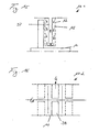
- a device 10 according to the invention in a pilot plant for sieve filtration of a suspension consisting of polyol and polystyrene particles contained therein will be explained in connection with FIG.
- a suspension tank 24 the suspension to be treated is passed to an inlet 17 of the device 10.
- the system is designed so that before introduction into the device 10 additives by means of a pumping device 25 of the suspension can be supplied.
- the suspension is conducted by means of a drive shaft 16 and stirring members 18 mounted thereon from the inlet 17 to a drain 22, wherein the suspension flows past the individual separating elements 12 of the disk-shaped separating elements 12.
- the Drive shaft is rotated by a motor 26 in rotation, which is controlled depending on the operation of a Abschlämmventiles 27 at the outlet 22.
- Controllable valves 30 are arranged on the permeate lines 28, by which means the differential pressure at individual separating elements 12 or at groups of separating elements 12 can be adjusted. In particular, by closing the valves 30, the differential pressure can be lowered to zero. During the release of the differential pressure, the drive shaft 16 remains in motion. Due to the elimination of the differential pressure, particles attached to the separating elements 12 can be removed even at a relatively low rotational speed of the drive shaft 16.
- the concentrated suspension also called retentate, discharged to a Retentattank 31.
- sensors for measuring the temperature, the pressure and / or the flow rate are provided on certain separating elements 12. Based on the determined values, not only a control of the valves 30 but also a control of the motor 26 and the means for generating the differential pressure can be performed.
- pumps may be provided in known manner on the suspension tank 24, the permeate tank 29, the retentate tank 31 or on corresponding supply lines.
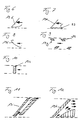
- FIG. 3 shows a preferred embodiment of a stirring blade 19a.
- the axial width of the stirring blade 19a decreases radially outward. This increases a distance s to the adjacent separating surfaces. Since the circumferential speed of the stirring blade 19a increases with increasing radial distance from the drive shaft, a constant shear gradient can be achieved in this way. This ensures a uniform and gentle treatment of the suspension.
- FIG. 4 shows a further embodiment of a stirring blade 19b.
- the cross-sectional shape of the stirring blade 19b changes in a radial direction.
- the cross-sectional shape is designed in this way that in a radial outer region of the stirring blade 19b, a suction effect is generated, while in a radially inner region in the stirring movement, an increased pressure is caused.
- the increased pressure effect has the advantage that a filter or sieve medium is increasingly pressed in the direction of the permeate space, so that even at a relatively low peripheral speed in the radially inner region an in-contact coming and thus wear between the stirring blade 19b and the filter - Or sieve medium is avoided.
- FIG. 5 shows in a cross-sectional view through a further embodiment of a stirring blade 19c a preferred flow profile, wherein the direction of movement of the stirring blade 19c is indicated by an arrow.
- a very strong gap flow is generated in a gap to the below in Figure 5 separating element due to the wedge-shaped configuration. Since the gap increases again in a region lying behind in the direction of movement, a diffuser effect is also achieved. This results in a reduction of the differential pressure, which promotes easier separation of particles and their subsequent swirling or mixing with the suspension.
- a stirring member having a plurality of stirring blades 19c By the movement of a stirring member having a plurality of stirring blades 19c, a rapid pressure pulsation with a strong cleaning effect is achieved.
- FIG. 6 shows a partial cross-sectional view of a further stirring blade 19d, in which only the region adjoining the separating element and forming the gap is formed with a flow profile for producing the diffuser effect.
- FIG. 8 shows a partial cross-sectional view of a further stirring blade 19f, in which the gap width is reduced counter to the direction of movement.
- a particularly high transverse flow velocity is achieved at the location of the smallest gap.
- FIG. 9 An energy-saving construction of individual web elements 34 of a stirring blade 19 g is shown in the cross-sectional view of FIG. 9.
- the webs 34 are provided only along the two adjacent separating surfaces, while the suspension can flow through a central region of the stirring blade 19g.
- a good suspension transport is alternatively achieved by a stirring blade 19h having a plate-like configuration, which results from the cross-sectional view of FIG.
- FIGS. 11 and 12 each show a double stirrer blade 19i and 19k. Both have an inner gap region through which a so-called suction bag is formed. In this case, a strong suction effect is achieved, at least in a lower region in the figures on the separating element, through which a base layer is particularly reliable detachable.
- FIG. 13 shows a schematic cross-sectional view of a further device 10a according to the invention.
- the stirring members 19 are formed as approximately disc-shaped rotors whose rotor planes are at an acute angle to an axis of rotation of the drive shaft 16.
- the stirring blades 19 Upon rotation, the stirring blades 19 perform a wobbling motion which causes additional pressure pulsation.
- Due to the parallel arrangement of the individual stirring members 19, a pressure and, on the other hand, a suction are exerted on a separating element 12 on the one hand. Due to the permeate space, these pressure forces influence and reinforce each other, so that an increased cleaning effect is achieved.
- FIG. 15 partially shows an embodiment of a device 10c according to the invention, in which a permeate is at a pressure difference which is largely independent of the radius can be dissipated.
- a trigger 37 is provided within the permeate space 15 of a separating element 12, in which the permeate can flow exclusively to a region and thus can flow, which lies in the radial direction close to the drive shaft 16.
- a cooling device 38 In the embodiment of a device 10d illustrated in FIG. 16, the use of a cooling device 38 is illustrated.
- the plate-shaped cooling device 38 is designed according to the shape of a separating element and provided instead of a separating element in a module 11 of the device 10c. By introducing a cooling liquid into the cooling device 38, a desired temperature setting can take place within the suspension space.
Landscapes
- Chemical & Material Sciences (AREA)
- Chemical Kinetics & Catalysis (AREA)
- Engineering & Computer Science (AREA)
- Water Supply & Treatment (AREA)
- Filtration Of Liquid (AREA)
- Centrifugal Separators (AREA)
- Separation Using Semi-Permeable Membranes (AREA)
Claims (24)
- Procédé pour séparer une suspension en un rétentat et un perméat, dans lequel :- la suspension est introduite dans un espace (14) de suspension comportant plusieurs modules (11) de type chambre, dans lesquels à chaque fois au moins un élément de séparation perméable (12) est prévu, avec une surface de séparation (13),- dans chaque module (11), au moins un organe d'agitation (18) est déplacé dans l'espace (14) de suspension à une faible distance au-dessus de la surface de séparation (13) et par rapport à celle-ci, de telle sorte qu'un écoulement transversal à la surface de séparation (13) est produit dans une fente entre l'organe d'agitation (18) et la surface de séparation (13),- une différence de pression est instaurée entre l'espace (14) de suspension et un espace (15) à perméat, qui se trouve sur un côté de l'élément de séparation (12) opposé à l'espace de suspension,- le perméat, qui traverse l'élément de séparation (12) en raison de la différence de pression existante, est évacué par une conduite (28) pour le perméat,- tandis que le rétentat épaissi est évacué de l'espace (14) de suspension par une évacuation (22),- pour nettoyer la surface de séparation (13) à des intervalles de temps déterminés, la différence de pression est supprimée pendant une durée définie, et- pendant l'intervalle de temps pendant lequel la différence de pression est supprimée, les organes (18) d'agitation continuent à bouger au-dessus de la surface de séparation (13),caractérisé en ce que- pour nettoyer les surfaces de séparation (13), la différence de pression est pilotée séparément et instaurée individuellement sur les différents éléments de séparation (12), la différence de pression étant mise à zéro sur certains éléments de séparation (12), tandis que la différence de pression demeure sur d'autres éléments de séparation (12).
- Procédé selon la revendication 1, caractérisé en ce que la suppression de la différence de pression est provoquée par une commande, en particulier l'interruption d'une alimentation en suspension, d'une évacuation du rétentat et/ou d'une évacuation du perméat.
- Procédé selon la revendication 1 ou 2, caractérisé en ce que la suspension est envoyée de l'alimentation (17) à l'évacuation (22) à travers plusieurs modules (11) de type chambre, dans' lesquels est placé à chaque fois au moins un élément de séparation (12) avec une conduite (28) pour le perméat, et en ce qu'une concentration de la suspension a lieu en direction de l'évacuation (22).
- Procédé selon la revendication 3, caractérisé en ce que l'évacuation du perméat depuis le module (11) est commandée séparément au moyen d'une vanne (30) placée sur la conduite (28) pour le perméat.
- Procédé selon l'une quelconque des revendications 1 à 4, caractérisé en ce qu'une filtration par tamis est effectuée, lors de laquelle l'élément de séparation (12) est conformé en milieu de tamisage, et en ce que le perméat est extrait avec une proportion de matières fines définie.
- Procédé selon l'une quelconque des revendications 1 à 5, caractérisé en ce que , dans l'intervalle de temps pendant lequel la différence de pression est supprimée, la vitesse de mouvement de l'organe d'agitation (18) est augmentée.
- Procédé selon l'une quelconque des revendications 1 à 6, caractérisé en ce que , dans l'intervalle de temps pendant lequel la différence de pression est supprimée, on procède à un rinçage du côté de l'espace (15) à perméat dans l'espace de suspension (14) .
- Procédé selon l'une quelconque des revendications 1 à 7, caractérisé en ce que la suspension est refroidie ou chauffée dans l'espace de suspension (14).
- Procédé selon l'une quelconque des revendications 1 à 8, caractérisé en ce que l'intervalle de temps pendant lequel la différence de pression est supprimée est fixé à une valeur comprise entre 5 secondes et 120 secondes.
- Procédé selon l'une quelconque des revendications 1 à 9, caractérisé en ce que les intervalles de temps entre deux suppressions successives de la différence de pression sont fixés entre 20 secondes et 1 heure.
- Procédé selon l'une quelconque des revendications 1 à 10, caractérisé en ce qu'on utilise une suspension comportant des particules molles de forme variable, en particulier une suspension contenant des particules de polymère, par exemple de polystyrène, dans un solvant organique, par exemple du polyol.
- Procédé selon l'une quelconque des revendications 1 à 11, caractérisé en ce que pour évacuer le rétentat, un organe de purge (27) placé sur l'évacuation (22) est ouvert brièvement selon des cycles temporels prédéfinis.
- Procédé selon l'une quelconque des revendications 1 à 12, caractérisé en ce qu' un liquide de lavage est introduit en plus dans l'espace de suspension (14), en particulier un lavage étant réalisé dans une direction allant de l'évacuation (22) à l'alimentation (17) .
- Dispositif pour séparer une suspension en un rétentat et un perméat, avec :- un espace (14) de suspension qui présente une alimentation (17) et une évacuation (22), l'espace (14) de suspension comprenant plusieurs modules (11),- au moins un élément de séparation perméable (12) dans chaque module (11) avec une surface de séparation (13) qui est voisine d'un espace (14) de suspension,- au moins un organe d'agitation (18) qui est placé dans l'espace (14) de suspension et est monté mobile à une faible distance au-dessus des surfaces de séparation (13),- un entraînement pour déplacer l'organe d'agitation (18) de manière relative au-dessus de la surface de séparation (13), de telle sorte qu'un écoulement transversal à la surface de séparation (13) puisse être produit dans une fente entre l'organe d'agitation (18) et la surface de séparation (13),- un espace (15) à perméat qui est séparé de l'espace de suspension (14) par l'élément de séparation (12), et- un dispositif pour produire une différence de pression entre l'espace de suspension (14) et l'espace (15) à perméat,caractérisé- en ce que des vannes (30) pouvant être commandées séparément sont prévues pour des conduites destinées à évacuer le perméat depuis l'espace (15) à perméat, et- en ce qu 'un dispositif de commande est prévu pour ouvrir et fermer individuellement les vannes (30) à des instants déterminés, les vannes (30) pouvant être commandées par le dispositif de commande pour supprimer la différence de pression, de telle manière que la différence de pression est mise à zéro sur certains éléments de séparation (12), tandis que la différence de pression demeure sur d'autres éléments de séparation (12).
- Dispositif selon la revendication 14, caractérisé en ce que l'élément de séparation perméable (12) est conformé en élément de tamisage avec des ouvertures de tamis qui présentent pour l'essentiel la même taille.
- Dispositif selon la revendication 14 ou 15, caractérisé
en ce que l'entraînement comprend un arbre d'entraînement (16) qui forme saillie dans l'espace (14) de suspension depuis le côté de l'alimentation (17) et est placé dans les modules au centre par rapport aux éléments de séparation (12) en forme de disque, et
en ce que les organes d'agitation (18) sont placés sur l'arbre d'entraînement (16). - Dispositif selon la revendication 16, caractérisé
en ce que l'organe d'agitation (18) entraîné autour d'un axe est conformé en rotor avec des pales agitatrices (19) d'extension essentiellement radiale,
en ce que les pales agitatrices (19) sont effilées radialement en direction de l'extérieur, de telle sorte qu'une distance entre la pale agitatrice (19) respective et la surface de séparation (13) s'élargit radialement en direction de l'extérieur. - Dispositif selon la revendication 16 ou 17, caractérisé
en ce que les pales agitatrices (19) d'un organe d'agitation (18) conformé en rotor sont disposées dans un plan de rotor,
en ce que les rotors sont disposés de façon décalée les uns par rapport aux autres selon un angle aigu par rapport à l'axe de l'arbre d'entraînement (16), et
en ce qu'entre les divers rotors est prévu à chaque fois un élément de séparation (12) comportant deux surfaces de séparation (13) opposées s'étendant pour l'essentiel radialement. - Dispositif selon l'une quelconque des revendications 14 à 18, caractérisé
en ce qu'un profil d'écoulement des pales agitatrices (19) est réalisé différemment sur une partie radialement intérieure et sur une partie radialement extérieure et
en ce qu 'une différence de pression plus grande peut être produite sur la partie radialement intérieure que sur la partie radialement extérieure des pales agitatrices (19). - Dispositif selon l'une quelconque des revendications 14 à 19, caractérisé en ce que les pales agitatrices (19) d'un organe d'agitation (18) conformé en rotor sont constituées chacune de plusieurs barres relativement étroites (34).
- Dispositif selon l'une quelconque des revendications 14 à 19, caractérisé en ce que les pales agitatrices (19) d'un organe d'agitation (18) conformé en rotor sont conformées chacune pour l'essentiel en plaque rectangulaire, qui est placée à angle droit par rapport à une surface de séparation (13) voisine.
- Dispositif selon l'une quelconque des revendications 14 à 21, caractérisé en ce qu'à l'intérieur de l'espace (15) à perméat est prévu un dispositif de rinçage par lequel un liquide de rinçage peut être envoyé de l'espace (15) à perméat à l'espace de suspension (14) à travers l'élément de séparation (12).
- Dispositif selon l'une quelconque des revendications 14 à 22, caractérisé en ce qu'à l'intérieur de l'espace de suspension (14) est placé au moins un dispositif de refroidissement (38) pour commander la température de la suspension.
- Dispositif selon l'une quelconque des revendications 14 à 23, caractérisé en ce qu'il est prévu un dispositif de lavage avec au moins une conduite de liquide de lavage qui débouche dans l'espace de suspension (14).
Applications Claiming Priority (2)
| Application Number | Priority Date | Filing Date | Title |
|---|---|---|---|
| DE19925397A DE19925397A1 (de) | 1999-06-02 | 1999-06-02 | Verfahren und Vorrichtung zur Fest-Flüssig-Trennung |
| DE19925397 | 1999-06-02 |
Publications (2)
| Publication Number | Publication Date |
|---|---|
| EP1057512A1 EP1057512A1 (fr) | 2000-12-06 |
| EP1057512B1 true EP1057512B1 (fr) | 2007-04-04 |
Family
ID=7910104
Family Applications (1)
| Application Number | Title | Priority Date | Filing Date |
|---|---|---|---|
| EP00101522A Expired - Lifetime EP1057512B1 (fr) | 1999-06-02 | 2000-01-26 | Méthode et dispositif de séparation solide-liquide |
Country Status (3)
| Country | Link |
|---|---|
| EP (1) | EP1057512B1 (fr) |
| AT (1) | ATE358518T1 (fr) |
| DE (2) | DE19925397A1 (fr) |
Families Citing this family (9)
| Publication number | Priority date | Publication date | Assignee | Title |
|---|---|---|---|---|
| DE10063484A1 (de) * | 2000-12-20 | 2002-07-04 | Bayer Ag | Siebfiltration von gefüllten Polyolen mit dynamischen Druckscheibenfiltern |
| DE10340366B4 (de) * | 2003-09-02 | 2008-12-18 | Khs Ag | Filtervorrichtung |
| WO2009075440A1 (fr) | 2007-12-11 | 2009-06-18 | Fil Max Co., Ltd. | Appareil de filtration utilisant un rotor pour un écoulement à étages multiples générant un tourbillon variable |
| DE102009004801A1 (de) * | 2009-01-13 | 2010-07-15 | Werner Lauth | Vorrichtung zum Filtern von Fluid-Feststoff-Gemischen |
| DE102010015871A1 (de) * | 2010-03-09 | 2011-09-15 | Tu Kaiserslautern | Vorrichtung zur verfahrenstechnischen Behandlung feststoffreicher Suspensionen |
| DE102010023020A1 (de) * | 2010-06-08 | 2011-12-08 | BOKELA Ingenieurgesellschaft für mechanische Verfahrenstechnik mbH | Verfahren und Vorrichtung zum Filtern eines Getränketrubes |
| CN103768846A (zh) * | 2014-01-10 | 2014-05-07 | 薛意 | 壁附式液体处理装置 |
| EP3241599B1 (fr) | 2016-05-03 | 2025-07-16 | BOKELA GmbH | Procede de separation d'une suspension a l'aide d'une filtration d'ecoulement transversal dans un concentre et produit de filtrage |
| CN111892127B (zh) * | 2020-08-27 | 2025-06-27 | 南京双强环境工程有限公司 | 一种新型一体化过滤装置 |
Family Cites Families (7)
| Publication number | Priority date | Publication date | Assignee | Title |
|---|---|---|---|---|
| US3884805A (en) * | 1974-05-13 | 1975-05-20 | Artisan Ind | Apparatus and process for continuous concentration of solids from a solids-containing fluid |
| US4066546A (en) * | 1974-10-25 | 1978-01-03 | Toshin Science Co., Ltd. | Continuous filtering process and an apparatus therefor |
| DE2836866A1 (de) * | 1978-08-23 | 1980-03-13 | Dynofag Ag | Verfahren und einrichtung zum abtrennen von fluessigkeiten aus suspensionen |
| PL139264B1 (en) * | 1983-01-19 | 1987-01-31 | Politechnika Warszawska | Dynamic filter |
| DE3927291A1 (de) * | 1988-08-26 | 1990-03-01 | Aquosmonic Wasserreinigungsger | Verfahren und vorrichtung zur umkehr-osmose |
| US5679249A (en) * | 1991-12-24 | 1997-10-21 | Pall Corporation | Dynamic filter system |
| EP0768112A1 (fr) * | 1995-10-16 | 1997-04-16 | Christ AG | Procédé et appareil pour produire de l'eau pure |
-
1999
- 1999-06-02 DE DE19925397A patent/DE19925397A1/de not_active Ceased
-
2000
- 2000-01-26 EP EP00101522A patent/EP1057512B1/fr not_active Expired - Lifetime
- 2000-01-26 AT AT00101522T patent/ATE358518T1/de active
- 2000-01-26 DE DE50014210T patent/DE50014210D1/de not_active Expired - Lifetime
Also Published As
| Publication number | Publication date |
|---|---|
| EP1057512A1 (fr) | 2000-12-06 |
| DE19925397A1 (de) | 2000-12-07 |
| DE50014210D1 (de) | 2007-05-16 |
| ATE358518T1 (de) | 2007-04-15 |
Similar Documents
| Publication | Publication Date | Title |
|---|---|---|
| EP0322649B1 (fr) | Procédé et dispositif de dégazage et de filtration des liquides | |
| DE3486197T2 (de) | Filtrierverfahren und Vorrichtung. | |
| DE2507202B2 (de) | Verfahren und Vorrichtung zur kontinuierlichen Trennung einer Feststoffeenthaltenden Flüssigkeit in eingedickten Schlamm und ein Filtrat | |
| DE19827473C1 (de) | Verbesserte Crossflow-Filterkassetten | |
| EP1967580B1 (fr) | Filtre à bière | |
| DE102011056633B4 (de) | Verfahren zum Reinigen eines Filters | |
| DE2545482A1 (de) | Filtrier-verfahren und -vorrichtung | |
| DE2323996A1 (de) | Geraet und verfahren zum absondern der traegerfluessigkeit von in ihr suspendierten teilchen | |
| EP2978519B1 (fr) | Dispositif de filtration et d'émulsification | |
| AT12648U1 (de) | Vorrichtung zum filtrieren von flüssigkeiten | |
| EP1154840A1 (fr) | Procede et dispositif de filtration a flux transversal | |
| WO1995015209A1 (fr) | Procede et dispositif de concentration de melanges solides/liquides selon une technologie faisant appel a des membranes | |
| EP1592489A2 (fr) | Dispositif de filtration et procede de filtration | |
| EP1057512B1 (fr) | Méthode et dispositif de séparation solide-liquide | |
| DE2251171A1 (de) | Filter | |
| DE2513751A1 (de) | Ultrafiltrationsanlage | |
| EP0577854A1 (fr) | Dispositif de filtration | |
| EP0353422B1 (fr) | Procédé et appareil de filtration | |
| DE2449817B2 (de) | Verfahren und einrichtung zur filtration fluessiger medien | |
| DE102010019873B4 (de) | Filtrationsvorrichtung | |
| WO2001096002A1 (fr) | Dispositif de filtration transversale de liquides | |
| DE4110943C1 (fr) | ||
| EP0747111B1 (fr) | Procédé pour augmenter la performance de filtration des filtres à courant transversal dans les modules des installations de filtration | |
| EP0525753A1 (fr) | Dispositif et procédé pour le filtrage des particules solides à partir de liquides | |
| EP1397190B1 (fr) | Dispositif de triage et de filtrage de melanges multiphases |
Legal Events
| Date | Code | Title | Description |
|---|---|---|---|
| PUAI | Public reference made under article 153(3) epc to a published international application that has entered the european phase |
Free format text: ORIGINAL CODE: 0009012 |
|
| 17P | Request for examination filed |
Effective date: 20000126 |
|
| AK | Designated contracting states |
Kind code of ref document: A1 Designated state(s): AT BE CH CY DE DK ES FI FR GB GR IE IT LI LU MC NL PT SE |
|
| AX | Request for extension of the european patent |
Free format text: AL;LT;LV;MK;RO;SI |
|
| RAP3 | Party data changed (applicant data changed or rights of an application transferred) |
Owner name: BOKELA INGENIEURGESELLSCHAFT FUER MECHANISCHE VERF |
|
| AKX | Designation fees paid |
Free format text: AT BE CH CY DE DK ES FI FR GB GR IE IT LI LU MC NL PT SE |
|
| 17Q | First examination report despatched |
Effective date: 20041126 |
|
| GRAP | Despatch of communication of intention to grant a patent |
Free format text: ORIGINAL CODE: EPIDOSNIGR1 |
|
| GRAS | Grant fee paid |
Free format text: ORIGINAL CODE: EPIDOSNIGR3 |
|
| GRAA | (expected) grant |
Free format text: ORIGINAL CODE: 0009210 |
|
| AK | Designated contracting states |
Kind code of ref document: B1 Designated state(s): AT BE CH CY DE DK ES FI FR GB GR IE IT LI LU MC NL PT SE |
|
| PG25 | Lapsed in a contracting state [announced via postgrant information from national office to epo] |
Ref country code: FI Free format text: LAPSE BECAUSE OF FAILURE TO SUBMIT A TRANSLATION OF THE DESCRIPTION OR TO PAY THE FEE WITHIN THE PRESCRIBED TIME-LIMIT Effective date: 20070404 |
|
| REG | Reference to a national code |
Ref country code: GB Ref legal event code: FG4D Free format text: NOT ENGLISH |
|
| REG | Reference to a national code |
Ref country code: CH Ref legal event code: EP |
|
| REG | Reference to a national code |
Ref country code: CH Ref legal event code: NV Representative=s name: SCHMAUDER & PARTNER AG PATENTANWALTSBUERO |
|
| REF | Corresponds to: |
Ref document number: 50014210 Country of ref document: DE Date of ref document: 20070516 Kind code of ref document: P |
|
| REG | Reference to a national code |
Ref country code: IE Ref legal event code: FG4D Free format text: LANGUAGE OF EP DOCUMENT: GERMAN |
|
| GBT | Gb: translation of ep patent filed (gb section 77(6)(a)/1977) |
Effective date: 20070517 |
|
| PG25 | Lapsed in a contracting state [announced via postgrant information from national office to epo] |
Ref country code: SE Free format text: LAPSE BECAUSE OF FAILURE TO SUBMIT A TRANSLATION OF THE DESCRIPTION OR TO PAY THE FEE WITHIN THE PRESCRIBED TIME-LIMIT Effective date: 20070704 |
|
| PG25 | Lapsed in a contracting state [announced via postgrant information from national office to epo] |
Ref country code: ES Free format text: LAPSE BECAUSE OF FAILURE TO SUBMIT A TRANSLATION OF THE DESCRIPTION OR TO PAY THE FEE WITHIN THE PRESCRIBED TIME-LIMIT Effective date: 20070715 |
|
| PG25 | Lapsed in a contracting state [announced via postgrant information from national office to epo] |
Ref country code: PT Free format text: LAPSE BECAUSE OF FAILURE TO SUBMIT A TRANSLATION OF THE DESCRIPTION OR TO PAY THE FEE WITHIN THE PRESCRIBED TIME-LIMIT Effective date: 20070904 |
|
| NLV1 | Nl: lapsed or annulled due to failure to fulfill the requirements of art. 29p and 29m of the patents act | ||
| ET | Fr: translation filed | ||
| REG | Reference to a national code |
Ref country code: IE Ref legal event code: FD4D |
|
| PG25 | Lapsed in a contracting state [announced via postgrant information from national office to epo] |
Ref country code: IE Free format text: LAPSE BECAUSE OF FAILURE TO SUBMIT A TRANSLATION OF THE DESCRIPTION OR TO PAY THE FEE WITHIN THE PRESCRIBED TIME-LIMIT Effective date: 20070404 Ref country code: DK Free format text: LAPSE BECAUSE OF FAILURE TO SUBMIT A TRANSLATION OF THE DESCRIPTION OR TO PAY THE FEE WITHIN THE PRESCRIBED TIME-LIMIT Effective date: 20070404 Ref country code: NL Free format text: LAPSE BECAUSE OF FAILURE TO SUBMIT A TRANSLATION OF THE DESCRIPTION OR TO PAY THE FEE WITHIN THE PRESCRIBED TIME-LIMIT Effective date: 20070404 |
|
| PLBE | No opposition filed within time limit |
Free format text: ORIGINAL CODE: 0009261 |
|
| STAA | Information on the status of an ep patent application or granted ep patent |
Free format text: STATUS: NO OPPOSITION FILED WITHIN TIME LIMIT |
|
| 26N | No opposition filed |
Effective date: 20080107 |
|
| PG25 | Lapsed in a contracting state [announced via postgrant information from national office to epo] |
Ref country code: IT Free format text: LAPSE BECAUSE OF FAILURE TO SUBMIT A TRANSLATION OF THE DESCRIPTION OR TO PAY THE FEE WITHIN THE PRESCRIBED TIME-LIMIT Effective date: 20070404 Ref country code: GR Free format text: LAPSE BECAUSE OF FAILURE TO SUBMIT A TRANSLATION OF THE DESCRIPTION OR TO PAY THE FEE WITHIN THE PRESCRIBED TIME-LIMIT Effective date: 20070705 |
|
| BERE | Be: lapsed |
Owner name: BOKELA INGENIEURGESELLSCHAFT FUR MECHANISCHE VERF Effective date: 20080131 |
|
| PG25 | Lapsed in a contracting state [announced via postgrant information from national office to epo] |
Ref country code: MC Free format text: LAPSE BECAUSE OF NON-PAYMENT OF DUE FEES Effective date: 20080131 |
|
| PG25 | Lapsed in a contracting state [announced via postgrant information from national office to epo] |
Ref country code: BE Free format text: LAPSE BECAUSE OF NON-PAYMENT OF DUE FEES Effective date: 20080131 |
|
| PG25 | Lapsed in a contracting state [announced via postgrant information from national office to epo] |
Ref country code: CY Free format text: LAPSE BECAUSE OF FAILURE TO SUBMIT A TRANSLATION OF THE DESCRIPTION OR TO PAY THE FEE WITHIN THE PRESCRIBED TIME-LIMIT Effective date: 20070404 |
|
| REG | Reference to a national code |
Ref country code: CH Ref legal event code: PCAR Free format text: SCHMAUDER & PARTNER AG PATENT- UND MARKENANWAELTE VSP;ZWAENGIWEG 7;8038 ZUERICH (CH) |
|
| PG25 | Lapsed in a contracting state [announced via postgrant information from national office to epo] |
Ref country code: LU Free format text: LAPSE BECAUSE OF NON-PAYMENT OF DUE FEES Effective date: 20080126 |
|
| REG | Reference to a national code |
Ref country code: FR Ref legal event code: PLFP Year of fee payment: 16 |
|
| PGFP | Annual fee paid to national office [announced via postgrant information from national office to epo] |
Ref country code: FR Payment date: 20150126 Year of fee payment: 16 Ref country code: AT Payment date: 20150127 Year of fee payment: 16 Ref country code: GB Payment date: 20150121 Year of fee payment: 16 |
|
| PGFP | Annual fee paid to national office [announced via postgrant information from national office to epo] |
Ref country code: DE Payment date: 20160129 Year of fee payment: 17 Ref country code: CH Payment date: 20160204 Year of fee payment: 17 |
|
| REG | Reference to a national code |
Ref country code: AT Ref legal event code: MM01 Ref document number: 358518 Country of ref document: AT Kind code of ref document: T Effective date: 20160126 |
|
| GBPC | Gb: european patent ceased through non-payment of renewal fee |
Effective date: 20160126 |
|
| REG | Reference to a national code |
Ref country code: FR Ref legal event code: ST Effective date: 20160930 |
|
| PG25 | Lapsed in a contracting state [announced via postgrant information from national office to epo] |
Ref country code: GB Free format text: LAPSE BECAUSE OF NON-PAYMENT OF DUE FEES Effective date: 20160126 |
|
| PG25 | Lapsed in a contracting state [announced via postgrant information from national office to epo] |
Ref country code: FR Free format text: LAPSE BECAUSE OF NON-PAYMENT OF DUE FEES Effective date: 20160201 Ref country code: AT Free format text: LAPSE BECAUSE OF NON-PAYMENT OF DUE FEES Effective date: 20160126 |
|
| REG | Reference to a national code |
Ref country code: DE Ref legal event code: R119 Ref document number: 50014210 Country of ref document: DE |
|
| REG | Reference to a national code |
Ref country code: CH Ref legal event code: PL |
|
| PG25 | Lapsed in a contracting state [announced via postgrant information from national office to epo] |
Ref country code: LI Free format text: LAPSE BECAUSE OF NON-PAYMENT OF DUE FEES Effective date: 20170131 Ref country code: CH Free format text: LAPSE BECAUSE OF NON-PAYMENT OF DUE FEES Effective date: 20170131 |
|
| PG25 | Lapsed in a contracting state [announced via postgrant information from national office to epo] |
Ref country code: DE Free format text: LAPSE BECAUSE OF NON-PAYMENT OF DUE FEES Effective date: 20170801 |