EP1057552A1 - Verfahren zum Zusammenbau eines Kugelgelenks und Dreieckslenker und Zusammenbau Kugelgelenk und Dreieckslenker hergestellt durch diesem Verfahren - Google Patents
Verfahren zum Zusammenbau eines Kugelgelenks und Dreieckslenker und Zusammenbau Kugelgelenk und Dreieckslenker hergestellt durch diesem Verfahren Download PDFInfo
- Publication number
- EP1057552A1 EP1057552A1 EP00401348A EP00401348A EP1057552A1 EP 1057552 A1 EP1057552 A1 EP 1057552A1 EP 00401348 A EP00401348 A EP 00401348A EP 00401348 A EP00401348 A EP 00401348A EP 1057552 A1 EP1057552 A1 EP 1057552A1
- Authority
- EP
- European Patent Office
- Prior art keywords
- ball joint
- assembly method
- creep
- assembly
- orifice
- Prior art date
- Legal status (The legal status is an assumption and is not a legal conclusion. Google has not performed a legal analysis and makes no representation as to the accuracy of the status listed.)
- Granted
Links
- 238000000034 method Methods 0.000 title claims abstract description 30
- 239000000725 suspension Substances 0.000 title claims description 16
- 229910052751 metal Inorganic materials 0.000 claims abstract description 12
- 230000000750 progressive effect Effects 0.000 claims abstract description 4
- 238000004080 punching Methods 0.000 claims description 9
- 238000006073 displacement reaction Methods 0.000 claims description 5
- 239000000463 material Substances 0.000 claims description 4
- 230000035939 shock Effects 0.000 claims description 3
- 239000002184 metal Substances 0.000 abstract description 5
- 230000002045 lasting effect Effects 0.000 description 3
- 210000004417 patella Anatomy 0.000 description 3
- 208000031968 Cadaver Diseases 0.000 description 1
- 239000013013 elastic material Substances 0.000 description 1
- 230000002093 peripheral effect Effects 0.000 description 1
- 238000010008 shearing Methods 0.000 description 1
- 238000004513 sizing Methods 0.000 description 1
Images

Classifications
-
- B—PERFORMING OPERATIONS; TRANSPORTING
- B21—MECHANICAL METAL-WORKING WITHOUT ESSENTIALLY REMOVING MATERIAL; PUNCHING METAL
- B21K—MAKING FORGED OR PRESSED METAL PRODUCTS, e.g. HORSE-SHOES, RIVETS, BOLTS OR WHEELS
- B21K25/00—Uniting components to form integral members, e.g. turbine wheels and shafts, caulks with inserts, with or without shaping of the components
-
- B—PERFORMING OPERATIONS; TRANSPORTING
- B21—MECHANICAL METAL-WORKING WITHOUT ESSENTIALLY REMOVING MATERIAL; PUNCHING METAL
- B21D—WORKING OR PROCESSING OF SHEET METAL OR METAL TUBES, RODS OR PROFILES WITHOUT ESSENTIALLY REMOVING MATERIAL; PUNCHING METAL
- B21D39/00—Application of procedures in order to connect objects or parts, e.g. coating with sheet metal otherwise than by plating; Tube expanders
- B21D39/06—Application of procedures in order to connect objects or parts, e.g. coating with sheet metal otherwise than by plating; Tube expanders of tubes in openings, e.g. rolling-in
-
- B—PERFORMING OPERATIONS; TRANSPORTING
- B23—MACHINE TOOLS; METAL-WORKING NOT OTHERWISE PROVIDED FOR
- B23P—METAL-WORKING NOT OTHERWISE PROVIDED FOR; COMBINED OPERATIONS; UNIVERSAL MACHINE TOOLS
- B23P11/00—Connecting or disconnecting metal parts or objects by metal-working techniques not otherwise provided for
Definitions
- the invention relates to a method of assembling a first metallic element of generally cylindrical shape such as that a ball joint assembly with a second metallic element of thin such as a suspension triangle.
- the invention also relates to a ball and triangle assembly of suspension assembled according to the process.
- An object of the present invention is to provide a method of assembly, in particular of a suspension triangle and a ball joint assembly, overcoming all or part of the disadvantages of the prior art noted above.
- the method comprises a step of forming a circular groove on the periphery of the first element, the deformation step consisting of ensure the creep of the edge of the orifice of the second element in the throat of the first element.
- the method comprises a step of forming at least one shoulder or circular bulge on the periphery of the first element, the deformation step consisting in ensuring the creep of the bulge so as to crimp the first element into the orifice of the second element.
- the deformation step consists in ensuring the creep of the bulge so as to immobilize the edge of the orifice of the second element between on the one hand the distorted bulge and on the other hand a second shoulder formed on the periphery of the first element.
- the deformation stage is made by means of two punches respectively lower and higher, the material flow of the first and / or second element being obtained by progressive effort lasting the order of a few seconds and / or brief shock lasting for the order of a fraction of a second.
- the punches have creep angles between approximately 10 and 19 degrees.
- At least one of the punches includes elastic means ensuring, during punching, offsetting about half the displacement of the first element relative to the other punch.
- the elastic means of compensation consist of a piece of material compressible and elastic interposed between the base of the first element and lower punch.
- the lower punch comprises a movable piece for holding the base of the first element, the elastic means of compensation consist of a spring urging the holding piece against the base of the first element.
- the first piece is a housing or ball joint assembly and the second part is a triangle suspension.
- the invention provides a method of assembling a first metallic element 1 of generally cylindrical shape, with a second thin metal element 2.
- the invention will be described below in its application to assembling a ball joint assembly with a triangle suspension.
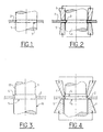
- the ball joint assembly 1 a circular groove 3.
- the ball joint assembly 1 is then placed or fitted into the orifice of the triangle suspension 2 so that the circular groove 3 is opposite of the border of the opening of triangle 2 (figure 1).
- the circular groove 3 has a corresponding width approximately the thickness of the suspension triangle 2.
- two punches respectively upper 7 and lower 6 can provide the creep of the metal from the edge of the orifice of the triangle in the throat.
- the creep of the triangle can be obtained by progressive force of the two punches 6, 7 with a duration of the order of a few seconds and / or by a brief shock lasting approximately one Fraction of a second.
- the punches 6 and 7 advantageously have angles of creep relative to the longitudinal axis of the ball joint assembly 1 between about 10 and 19 degrees, and preferably 15 degrees.
- Figures 3 and 4 show another form of carrying out the assembly process according to the invention in which the outer surface of the ball joint assembly 1 comprises three successive portions 10, 4, 11 having respectively three different diameters.
- the three portions 11, 4, 10 are arranged in order of increasing diameter in the direction of top to bottom of Figure 3.
- the middle portion 4, hereinafter called bulge has a small width, of the order for example twice the thickness of the suspension triangle 2.
- the diameter of the bulge 4 corresponds substantially the diameter of the orifice of the triangle 2.
- the ball joint assembly 1 is arranged in the opening of triangle 2.
- One of the faces of the border of the orifice rests on a shoulder 5 formed at the junction between the portion 10 which has the largest diameter and the bulge 4 (figure 4).
- a deformation is carried out or creep of the bulge 4 so as to immobilize the border of the orifice of the triangle 2 enters on the one hand the deformation bulge 4 and on the other hand the shoulder 5.
- FIG. 5 shows in more detail the means of punching mentioned above.
- At least one of the punches comprises preferably elastic means ensuring during punching compensation about half the displacement of the patella relative to the other punch.
- the compensation means are sized to avoid a shearing of parts 1, 2 assembled during punching.
- the elastic means of compensation can consist of a piece 8 in compressible and elastic material, such as rubber, interposed between the base of the ball joint assembly 1 and the punch lower 7.
- the elastic piece 8 allows to compensate downward for half the displacement of the parts 1, 2 with respect to the upper punch 7.
- FIG. 6 represents an alternative embodiment of the punching means in which a moving part in sliding 10 in the lower punch 6 maintains of the base of the ball joint assembly 1 by means of a spring 9.
- the movable piece 10 for holding and the spring 9 constitute means of compensating for the displacement of the ball joint assembly 1 with respect to the upper punch 7.
- Identical elements to those described above with reference to Figure 5 are designated by the same reference numerals.
- the method according to the invention allows to bind and immobilize a cylindrical element in a thin piece in a simple way, without require additional fasteners.
- This assembly process is particularly suitable for connection of a ball joint and suspension triangle assembly.
- the bond which is simplified, does not disturb the internal mechanism of the patella.
- the connection is rigid and not removable, without damaging the arm or the assembly patella.
- the assembly operation is less costly and faster than known traditional solutions.
Landscapes
- Engineering & Computer Science (AREA)
- Mechanical Engineering (AREA)
- Pivots And Pivotal Connections (AREA)
Applications Claiming Priority (2)
| Application Number | Priority Date | Filing Date | Title |
|---|---|---|---|
| FR9906943 | 1999-06-02 | ||
| FR9906943A FR2794387B1 (fr) | 1999-06-02 | 1999-06-02 | Procede d'assemblage d'un premier element metallique de forme generale cylindrique avec un second element matallique de faible epaisseur, et ensemble rotule et triangle de suspension assembles selon le procede |
Publications (2)
| Publication Number | Publication Date |
|---|---|
| EP1057552A1 true EP1057552A1 (de) | 2000-12-06 |
| EP1057552B1 EP1057552B1 (de) | 2004-02-25 |
Family
ID=9546269
Family Applications (1)
| Application Number | Title | Priority Date | Filing Date |
|---|---|---|---|
| EP20000401348 Expired - Lifetime EP1057552B1 (de) | 1999-06-02 | 2000-05-17 | Kombination von einem Kugelgelenk und einem Dreieckslenker |
Country Status (4)
| Country | Link |
|---|---|
| EP (1) | EP1057552B1 (de) |
| DE (1) | DE60008456T2 (de) |
| ES (1) | ES2213552T3 (de) |
| FR (1) | FR2794387B1 (de) |
Cited By (5)
| Publication number | Priority date | Publication date | Assignee | Title |
|---|---|---|---|---|
| EP1291121A3 (de) * | 2001-09-11 | 2003-12-03 | Moeller GmbH | Befestigungsverfahren, Montagewerkzeug und Stützhebel für ein Schaltschloss eines Leistungsschalters, bzw. Lasttrennschalters |
| WO2003074209A3 (en) * | 2002-03-06 | 2004-02-26 | Adcock Tech Ltd | A method of manufacture of a metallic component apparatus for use in the method and method of finishing a metallic component |
| GB2389066B (en) * | 2002-03-06 | 2005-08-17 | Adcock Tech Ltd | A method of manufacture of a metallic component,apparatus for use in the method and a method of finishing a metallic component |
| DE102005060719A1 (de) * | 2005-12-19 | 2007-06-21 | Siemens Ag | Verfahren zum Verstemmen eines ersten Teiles |
| EP2490243A1 (de) * | 2011-02-16 | 2012-08-22 | Eaton Corporation | Verriegelungsanordnung und elektrische Schaltvorrichtung damit |
Families Citing this family (1)
| Publication number | Priority date | Publication date | Assignee | Title |
|---|---|---|---|---|
| DE102007007932B3 (de) * | 2007-02-17 | 2008-12-18 | Daimler Ag | Verfahren und Vorrichtung zum Verbinden eines Anschlussbauteils mit einem Innenhochdruckumformteil |
Citations (6)
| Publication number | Priority date | Publication date | Assignee | Title |
|---|---|---|---|---|
| JPS57146444A (en) * | 1981-03-06 | 1982-09-09 | Hitachi Ltd | Joining structure of two metallic members |
| DE3145469A1 (de) * | 1981-11-16 | 1983-05-19 | Wabco Westinghouse Fahrzeugbremsen GmbH, 3000 Hannover | Verfahren und vorrichtung zur herstellung einer kraft- und formschluessigen verbindung |
| JPS58135735A (ja) * | 1982-02-05 | 1983-08-12 | Hitachi Ltd | 金属板に金属管を固着する方法 |
| EP0220165A2 (de) * | 1985-10-21 | 1987-04-29 | Bombardier-Rotax-Wien Produktions- und Vertriebsgesellschaft m.b.H. | Verfahren zum Sichern eines Schraubbolzens, insbesondere eines Stiftschraubbolzens, in einer Gewindebohrung eines Werkstückes, Schraubbolzen und Werkzeug zur Durchführung des Verfahrens |
| US4667989A (en) * | 1986-01-17 | 1987-05-26 | Murray Europe S.P.A. | Leak-free and vibration resistant pipe-flange coupling |
| US5630288A (en) * | 1994-02-04 | 1997-05-20 | Administration Des Monnaies Et Medailles | Process for manufacturing bimetallic coins or medals and coins or medals thus obtained |
-
1999
- 1999-06-02 FR FR9906943A patent/FR2794387B1/fr not_active Expired - Fee Related
-
2000
- 2000-05-17 DE DE2000608456 patent/DE60008456T2/de not_active Expired - Lifetime
- 2000-05-17 EP EP20000401348 patent/EP1057552B1/de not_active Expired - Lifetime
- 2000-05-17 ES ES00401348T patent/ES2213552T3/es not_active Expired - Lifetime
Patent Citations (6)
| Publication number | Priority date | Publication date | Assignee | Title |
|---|---|---|---|---|
| JPS57146444A (en) * | 1981-03-06 | 1982-09-09 | Hitachi Ltd | Joining structure of two metallic members |
| DE3145469A1 (de) * | 1981-11-16 | 1983-05-19 | Wabco Westinghouse Fahrzeugbremsen GmbH, 3000 Hannover | Verfahren und vorrichtung zur herstellung einer kraft- und formschluessigen verbindung |
| JPS58135735A (ja) * | 1982-02-05 | 1983-08-12 | Hitachi Ltd | 金属板に金属管を固着する方法 |
| EP0220165A2 (de) * | 1985-10-21 | 1987-04-29 | Bombardier-Rotax-Wien Produktions- und Vertriebsgesellschaft m.b.H. | Verfahren zum Sichern eines Schraubbolzens, insbesondere eines Stiftschraubbolzens, in einer Gewindebohrung eines Werkstückes, Schraubbolzen und Werkzeug zur Durchführung des Verfahrens |
| US4667989A (en) * | 1986-01-17 | 1987-05-26 | Murray Europe S.P.A. | Leak-free and vibration resistant pipe-flange coupling |
| US5630288A (en) * | 1994-02-04 | 1997-05-20 | Administration Des Monnaies Et Medailles | Process for manufacturing bimetallic coins or medals and coins or medals thus obtained |
Non-Patent Citations (2)
| Title |
|---|
| PATENT ABSTRACTS OF JAPAN vol. 006, no. 249 (M - 177) 8 December 1982 (1982-12-08) * |
| PATENT ABSTRACTS OF JAPAN vol. 007, no. 250 (M - 254) 8 November 1983 (1983-11-08) * |
Cited By (10)
| Publication number | Priority date | Publication date | Assignee | Title |
|---|---|---|---|---|
| EP1291121A3 (de) * | 2001-09-11 | 2003-12-03 | Moeller GmbH | Befestigungsverfahren, Montagewerkzeug und Stützhebel für ein Schaltschloss eines Leistungsschalters, bzw. Lasttrennschalters |
| WO2003074209A3 (en) * | 2002-03-06 | 2004-02-26 | Adcock Tech Ltd | A method of manufacture of a metallic component apparatus for use in the method and method of finishing a metallic component |
| GB2389066B (en) * | 2002-03-06 | 2005-08-17 | Adcock Tech Ltd | A method of manufacture of a metallic component,apparatus for use in the method and a method of finishing a metallic component |
| GB2412339A (en) * | 2002-03-06 | 2005-09-28 | Adcock Tech Ltd | Method of forming a gear |
| GB2412339B (en) * | 2002-03-06 | 2005-11-02 | Adcock Tech Ltd | A method of forming a gear |
| DE102005060719A1 (de) * | 2005-12-19 | 2007-06-21 | Siemens Ag | Verfahren zum Verstemmen eines ersten Teiles |
| EP2490243A1 (de) * | 2011-02-16 | 2012-08-22 | Eaton Corporation | Verriegelungsanordnung und elektrische Schaltvorrichtung damit |
| CN102683126A (zh) * | 2011-02-16 | 2012-09-19 | 伊顿公司 | 锁止组件及包含该锁止组件的电开关设备 |
| US8507817B2 (en) | 2011-02-16 | 2013-08-13 | Eaton Corporation | Latch assembly and electrical switching apparatus including the same |
| CN102683126B (zh) * | 2011-02-16 | 2015-10-21 | 伊顿公司 | 锁止组件及包含该锁止组件的电开关设备 |
Also Published As
| Publication number | Publication date |
|---|---|
| DE60008456T2 (de) | 2004-12-16 |
| DE60008456D1 (de) | 2004-04-01 |
| ES2213552T3 (es) | 2004-09-01 |
| FR2794387B1 (fr) | 2001-07-27 |
| EP1057552B1 (de) | 2004-02-25 |
| FR2794387A1 (fr) | 2000-12-08 |
Similar Documents
| Publication | Publication Date | Title |
|---|---|---|
| EP0751305A1 (de) | Anordnung zur Befestigung eines Elementes von einem Scheibenwischer an einer Kraftfahrzeugkarrosserie | |
| EP0755843B1 (de) | Höhenverstellbare Lenksäule mit Führungseinrichtung | |
| EP1175638A1 (de) | Federscharnierbauteil für brillenfassung | |
| FR2925636A1 (fr) | Systeme de montage de patin de frein a disque. | |
| EP0311498A1 (de) | Befestigungssysteme mit in Käfigen eingefassten Muttern | |
| WO2002095259A1 (fr) | Support antivibratoire et procede de fabrication d"un tel support | |
| EP1057552B1 (de) | Kombination von einem Kugelgelenk und einem Dreieckslenker | |
| EP1963688B1 (de) | Anordnung zur zusammensetzung zweier teile durch schraubbefestigung über ein schrauben-muttern-system | |
| EP0300857A1 (de) | Zusammenbauverfahren für einen Servomotor und nach diesem Verfahren Zusammengebauter Servomotor | |
| EP3070343B1 (de) | Vorrichtung zum befestigen, die einen teil mit einer öffnung und einem an diese öffnung befestigten metallband umfasst | |
| FR2815684A1 (fr) | Ecran de protection de disque de frein et ensemble pour le raccordement a rotation d'une roue a un vehicule routier, comportant un tel ecran | |
| EP2342404B1 (de) | Mechanisches modul für einen fahrzeugschlüssel und herstellungsverfahren dafür | |
| EP1882864A1 (de) | Befestigung eines Kupplungsausrücklagers mit einem Haltering für das Mittel, das die Selbstzentrierungskraft ausübt | |
| FR2691767A1 (fr) | Dispositif de liaison élastique à rotule. | |
| EP1588897B1 (de) | Haltemittel und zugehöriges Fahrzeug | |
| FR2910383A1 (fr) | Butee de suspension pourvue d'une coupelle et procede de fabrication d'une butee de suspension. | |
| EP1778422B1 (de) | Crimpwerkzeug | |
| EP1459869A2 (de) | Teil zum Auflegen auf ein Karosseriebauteil, Karosseriebauteil dafür geeignet und Baugruppe aus diesen beiden Teilen | |
| FR2732166A1 (fr) | Boitier de connecteur reguide | |
| WO2005108188A1 (fr) | Procédé de fabrication d'une pièce en tôle par emboutissage et pliage, dispositif de fabrication, pièce en tôle, berceau de véhicule, coquille de berceau et véhicule correspondants | |
| EP1317355A1 (de) | Befestigungsverfahren für mindestens einen führungseinsatz zwischen zwei koaxialen rohren, bevorzugt in einem kraftfahrzeug-stabilisator | |
| WO2005080816A1 (fr) | Embrayage a mecanisme perfectionne et procede de montage de cet embrayage | |
| WO1999008037A1 (fr) | Dispositif de raccordement rapide d'un tube a un element rigide | |
| EP3558761B1 (de) | Fahrzeugteil zum verschweissen mit einem karosserieelement | |
| EP3844405A1 (de) | Vorrichtung zum verbinden von rohrförmigen elementen |
Legal Events
| Date | Code | Title | Description |
|---|---|---|---|
| PUAI | Public reference made under article 153(3) epc to a published international application that has entered the european phase |
Free format text: ORIGINAL CODE: 0009012 |
|
| AK | Designated contracting states |
Kind code of ref document: A1 Designated state(s): DE ES GB IT |
|
| AX | Request for extension of the european patent |
Free format text: AL;LT;LV;MK;RO;SI |
|
| 17P | Request for examination filed |
Effective date: 20010216 |
|
| AKX | Designation fees paid |
Free format text: DE ES GB IT |
|
| 17Q | First examination report despatched |
Effective date: 20021014 |
|
| GRAP | Despatch of communication of intention to grant a patent |
Free format text: ORIGINAL CODE: EPIDOSNIGR1 |
|
| RTI1 | Title (correction) |
Free format text: ASSEMBLY OF A BALL JOINT AND A TRIANGULAR SUSPENSION ARM |
|
| GRAS | Grant fee paid |
Free format text: ORIGINAL CODE: EPIDOSNIGR3 |
|
| GRAA | (expected) grant |
Free format text: ORIGINAL CODE: 0009210 |
|
| AK | Designated contracting states |
Kind code of ref document: B1 Designated state(s): DE ES GB IT |
|
| REG | Reference to a national code |
Ref country code: GB Ref legal event code: FG4D Free format text: NOT ENGLISH |
|
| GBT | Gb: translation of ep patent filed (gb section 77(6)(a)/1977) |
Effective date: 20040225 |
|
| REF | Corresponds to: |
Ref document number: 60008456 Country of ref document: DE Date of ref document: 20040401 Kind code of ref document: P |
|
| REG | Reference to a national code |
Ref country code: ES Ref legal event code: FG2A Ref document number: 2213552 Country of ref document: ES Kind code of ref document: T3 |
|
| PLBE | No opposition filed within time limit |
Free format text: ORIGINAL CODE: 0009261 |
|
| STAA | Information on the status of an ep patent application or granted ep patent |
Free format text: STATUS: NO OPPOSITION FILED WITHIN TIME LIMIT |
|
| 26N | No opposition filed |
Effective date: 20041126 |
|
| PGFP | Annual fee paid to national office [announced via postgrant information from national office to epo] |
Ref country code: GB Payment date: 20050422 Year of fee payment: 6 |
|
| PGFP | Annual fee paid to national office [announced via postgrant information from national office to epo] |
Ref country code: ES Payment date: 20050505 Year of fee payment: 6 |
|
| PG25 | Lapsed in a contracting state [announced via postgrant information from national office to epo] |
Ref country code: GB Free format text: LAPSE BECAUSE OF NON-PAYMENT OF DUE FEES Effective date: 20060517 |
|
| PG25 | Lapsed in a contracting state [announced via postgrant information from national office to epo] |
Ref country code: ES Free format text: LAPSE BECAUSE OF NON-PAYMENT OF DUE FEES Effective date: 20060518 |
|
| PGFP | Annual fee paid to national office [announced via postgrant information from national office to epo] |
Ref country code: IT Payment date: 20060531 Year of fee payment: 7 |
|
| GBPC | Gb: european patent ceased through non-payment of renewal fee |
Effective date: 20060517 |
|
| REG | Reference to a national code |
Ref country code: ES Ref legal event code: FD2A Effective date: 20060518 |
|
| PG25 | Lapsed in a contracting state [announced via postgrant information from national office to epo] |
Ref country code: IT Free format text: LAPSE BECAUSE OF NON-PAYMENT OF DUE FEES Effective date: 20070517 |
|
| PGFP | Annual fee paid to national office [announced via postgrant information from national office to epo] |
Ref country code: DE Payment date: 20130423 Year of fee payment: 14 |
|
| REG | Reference to a national code |
Ref country code: DE Ref legal event code: R119 Ref document number: 60008456 Country of ref document: DE |
|
| REG | Reference to a national code |
Ref country code: DE Ref legal event code: R119 Ref document number: 60008456 Country of ref document: DE Effective date: 20141202 |
|
| PG25 | Lapsed in a contracting state [announced via postgrant information from national office to epo] |
Ref country code: DE Free format text: LAPSE BECAUSE OF NON-PAYMENT OF DUE FEES Effective date: 20141202 |