EP1057712A2 - Kraftfahrzeuglenkung - Google Patents
Kraftfahrzeuglenkung Download PDFInfo
- Publication number
- EP1057712A2 EP1057712A2 EP00110920A EP00110920A EP1057712A2 EP 1057712 A2 EP1057712 A2 EP 1057712A2 EP 00110920 A EP00110920 A EP 00110920A EP 00110920 A EP00110920 A EP 00110920A EP 1057712 A2 EP1057712 A2 EP 1057712A2
- Authority
- EP
- European Patent Office
- Prior art keywords
- steering column
- airbag
- steering
- motor vehicle
- driver
- Prior art date
- Legal status (The legal status is an assumption and is not a legal conclusion. Google has not performed a legal analysis and makes no representation as to the accuracy of the status listed.)
- Granted
Links
Images

Classifications
-
- B—PERFORMING OPERATIONS; TRANSPORTING
- B60—VEHICLES IN GENERAL
- B60R—VEHICLES, VEHICLE FITTINGS, OR VEHICLE PARTS, NOT OTHERWISE PROVIDED FOR
- B60R21/00—Arrangements or fittings on vehicles for protecting or preventing injuries to occupants or pedestrians in case of accidents or other traffic risks
- B60R21/02—Occupant safety arrangements or fittings, e.g. crash pads
- B60R21/16—Inflatable occupant restraints or confinements designed to inflate upon impact or impending impact, e.g. air bags
- B60R21/20—Arrangements for storing inflatable members in their non-use or deflated condition; Arrangement or mounting of air bag modules or components
- B60R21/203—Arrangements for storing inflatable members in their non-use or deflated condition; Arrangement or mounting of air bag modules or components in steering wheels or steering columns
-
- B—PERFORMING OPERATIONS; TRANSPORTING
- B62—LAND VEHICLES FOR TRAVELLING OTHERWISE THAN ON RAILS
- B62D—MOTOR VEHICLES; TRAILERS
- B62D1/00—Steering controls, i.e. means for initiating a change of direction of the vehicle
- B62D1/02—Steering controls, i.e. means for initiating a change of direction of the vehicle vehicle-mounted
- B62D1/16—Steering columns
- B62D1/18—Steering columns yieldable or adjustable, e.g. tiltable
- B62D1/19—Steering columns yieldable or adjustable, e.g. tiltable incorporating energy-absorbing arrangements, e.g. by being yieldable or collapsible
- B62D1/197—Steering columns yieldable or adjustable, e.g. tiltable incorporating energy-absorbing arrangements, e.g. by being yieldable or collapsible incorporating devices for preventing ingress of the steering column into the passengers space in case of accident
Definitions
- the invention is based on a motor vehicle steering, in particular one Commercial vehicle steering, according to the preamble of claim 1.
- Such a motor vehicle steering system contains a steering column, which usually has a Airbag provided steering wheel.
- the steering column is on an end wall of the Motor vehicle body supported and compared to this at a certain angle inclined.
- a frontal impact of the motor vehicle it occurs because of the Deformation of the front wall and due to the acceleration of the upper part of the steering column forward to a change in the steering column inclination in the form of an upward movement the steering wheel.
- An unfavorable position of the driver relative to that from the Steering wheel leaking airbag is the result.
- the result can be a high breast intrusion often because only the head is caught by the airbag and the chest of the Drives through on the lower steering wheel rim and not through as planned the airbag is supported.
- the steering column In the case of commercial vehicles, the steering column is already set relatively steeply in the initial state, so that the angle of the driver's torso relative to the steering wheel on impact assuming that the inclination of the frontal crash remains unchanged Steering column is unfavorable. As a rule, the steering column turns in the event of a frontal crash but still further, so that the problem of a commercial vehicle particularly low support of the chest area by the steering wheel airbag results.
- DE 35 44 345 A1 discloses a motor vehicle steering system in which the Steering column by means of an energy store that can be released by a collision sensor is pivotable about a pivot axis to the unwanted inclination of the To compensate for the steering wheel.
- the energy store according to the known document can be a cylinder piston drive act, which has a force-transmitting connection with the Steering column is connected and in the event of a collision by pressurizing the steering column pivots in the desired manner about the pivot axis.
- the appears Time required to pressurize the cylinder piston drive measured by the sudden upper body displacement of the driver long to ensure timely tilt adjustment of the steering column.
- to supply the cylinder-piston drive pressure medium in constantly be stored in a container, whereby by inevitable with time Leakage losses there is a risk of ineffectiveness of the inclination adjustment.
- the energy store contains one in operative connection with the steering column and under tension Spring, whereby in the event of a collision the locking of the steering column is released by detonation and thereby the spring a torque on the now freely pivoting steering column can exercise.
- the disadvantage here is that the spring is constantly under tension stands, which is why it wears off over time.
- the present invention is based on the object, a motor vehicle steering of the type mentioned at the outset, by means of which in the event of a collision a pivoting of the steering column towards the driver with the commanded high speed and also reliable over a longer period of time is guaranteed.
- the motor vehicle steering system according to the invention has the advantage that the sudden and at the same time as the steering wheel airbag unfolds the additional Airbags reached the desired steering column tilt adjustment extremely quickly becomes. This means that the steering wheel airbag has unfavorable angular positions relative to the driver Can be corrected before the driver hits the steering wheel airbag is coming.
- the one generated by triggering the additional airbag The steering column swivels towards the driver regardless of the degree of deformation of the vehicle body, so that especially in commercial vehicles Even in the collision-free initial state, the angular position is unfavorable Steering column can be corrected even with slight deformations of the vehicle body.
- the locking of the Steering column opposite the vehicle body a driver-operated adjustment mechanism for tilt and axial adjustment of the steering column, the additional Airbag in collision-free operation not in operative connection with the steering column or stands the adjustment mechanism and in the event of a collision against a stop Steering column can be hit.
- the adjustment mechanism Steering column remains adjustable, unaffected by the additional airbag, on the other hand but the airbag when triggered in any adjustment position of the steering column, d. H. can exert forces on the steering column in any position relative to the airbag. Since the additional airbag due to the lack of an active connection a distance to the stop has on the steering column, has its shell when hitting the stop an already high speed. Compared to a solution in which the airbag cover is coupled directly to the steering column, the high stroke impulse has a special effect quick release of the locking of the steering column.
- the additional airbag is an airbag commonly used as a side airbag is and can be triggered by a signal from an airbag control unit, which a Passenger airbag is intended.
- an airbag control unit which a Passenger airbag is intended.
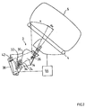
- the vehicle steering system designated overall by 1 in FIG. 1 is according to the preferred one Embodiment a commercial vehicle steering.
- the commercial vehicle steering 1 contains a steering wheel 4 arranged at the upper end of a steering column 2 with a steering wheel airbag 6, which according to the collision-free state shown in Fig.1 Commercial vehicle is not deployed.
- the steering column 2 contains an upper steering column part 8 with a tubular casing 10, in which rotatably received a steering spindle connected to the steering wheel 4 is, which in turn is connected to a steering gear, not shown.
- the upper steering column part 8 takes a steering column inclination ⁇ relative to the vertical, which is relatively low in commercial vehicles and is derived from this an unfavorable impact angle of the driver on the steering wheel 4 results.
- the upper steering column part 8 closes a lower, compared to the upper Steering column part 8 at an obtuse-angled steering column part, which as a U-shaped, downwardly sliding plate 12 is formed.
- the two legs 14 of the U-shaped sliding plate 12 are of two cheeks 16 one on the vehicle body attached steering column bracket 18 encompassed and within the cheeks 16 by means of a sliding guide 20 guided and pivoted, because of the Side view according to Figure 1 only one leg 14 and one cheek 16 can be seen are.
- the link guide 20 forms part of a driver-operated adjustment mechanism 22 of the steering column 2, which in addition 1 in the area of the link guide 20 pneumatic cylinder-piston unit shown by a dashed circular line 24 and a pivot axis 26.
- the pneumatic cylinder-piston unit 24 is on the steering column bracket 18 parallel to the pivot axis 26 between the two legs 14 of the lower steering column part forming U-shaped sliding plate 12 is added, at the free ends of their Piston and cylinder jaws 28 are formed, which also in Fig.1 are indicated by a dashed arc.
- the pneumatic cylinder-piston unit 24 is pressurized and actuated by the driver can be relieved of pressure, whereby when pressurized by the then inward moving jaws 28, the legs 14 of the U-shaped sliding plate 12 to cancel an existing frictional connection from the inside of the cheeks 16 of the steering column bracket 18 relax and thus a shift and Swiveling of the steering column 2 relative to the stationary steering column bracket 18 in The scope of the scope given by the guide 20 is made possible.
- the guide 20 comprises on the one hand as straight cutouts in the cheeks 16 of the steering column bracket 18 formed and parallel to the upper steering column part 8 extending sliding scenes 30 and on the other hand as circular arc sections formed in the legs 14 of the U-shaped sliding plate 12 and in the circumferential direction of an imaginary circular path about the pivot axis 26 extending pivot link 32, the sliding link 30 and the Cover swivel links 32 crossing in pairs on both sides and by means of the Clamping jaws 28 of the pneumatic cylinder-piston unit 24 axially centered to the outside protruding stub axles 34 are guided against each other.
- the pivot axis consists of a with the upper end of the U-shaped sliding plate 12 related and transverse to this Roller 26, the ends of which in guide rails 36 in the cheeks 16 of the steering column bracket 18 are guided on both sides. To enable adjustment in the same direction, are the guide rails 36 parallel to the longitudinal extent of the sliding link 30 arranged.
- the steering column When the pneumatic cylinder-piston unit 24 is under pressure, the steering column can thus 2 relative to the steering column bracket 18 along the sliding link 30 axially and at the same time their inclination can be adjusted about the pivot axis 26, whereby they are about the pivot axis held in the guide rails 36 of the steering column bracket 18 26 is supported and the pivoting movement is guided through the pivot link 32 becomes.
- the set position of the steering column 2 is then by the driver-operated Relief of pressure and via spring spring of the pneumatic cylinder-piston unit 24 generated friction between the legs 14 of the lower steering column part 12 and the cheeks 16 of the steering column bracket 18 can be fixed.
- An inventive provided and designed as an additional airbag 38 Actuator for suddenly adjusting the inclination of the steering column 2 during a frontal collision is attached to a lower strut 40 of the steering column bracket 18 and lies in the undeployed state at a distance from a webbing 42, which is arranged at the lower end of the lower steering column part 12 and its connects both legs 14 with a slight sag.
- the Legs 14 tabs provided through which the ends of the webbing 42nd are led. Due to the spacing from the webbing 42, the additional airbag is available 38 in collision-free operation not in operative connection with the steering column 2, which is why this remains unaffected by the additional airbag 38 driver-operated adjustable.
- the additional airbag 38 is a conventional in the preferred embodiment airbag used as a side airbag and one by a signal of the channel Airbag control unit 44 can be triggered, which is a passenger airbag in a passenger car would be assigned. As no passenger airbags are provided for commercial vehicles are, the additional airbag 38 can occupy the free channel of the passenger airbag.
- a trigger signal for the additional airbag 38 and for the steering wheel airbag 6 from Airbag control unit 44 are controlled at the same time, so that both airbags 6, 38 unfold at the same time.
- the additional airbag 38 deploys in the direction of the webbing 42 closes and strikes it, which then moves upwards evasive because of its slight sag it can nestle against him and transmits the stop pulse to the steering column 2, which is because of the between the belt strap 42 and the pivot axis 26 formed lever arm a torque is generated on the steering column 2 about the pivot axis 26. Because the additional Airbag 38 and the pivot axis 26 at different ends of the lower steering column part 12 are arranged, there is a relatively large lever arm length, what has a favorable effect on the swivel torque generated.
- the impact pulse of the additional airbag 38 against the webbing could 42 be so large that the frictional engagement between the steering column 2 and the Steering column bracket 18 can be overcome without loosening the friction connection.
- the steering column pivots through the impulse of the additional airbag 38 clockwise until the lower ends of the in the legs 14 of the lower steering column part 12 formed pivot link 32 on the stub axles 34 of the stationary pneumatic cylinder-piston unit Strike 24.
Landscapes
- Engineering & Computer Science (AREA)
- Mechanical Engineering (AREA)
- Chemical & Material Sciences (AREA)
- Combustion & Propulsion (AREA)
- Transportation (AREA)
- Air Bags (AREA)
- Steering Controls (AREA)
Abstract
Description
- Fig. 1
- eine Seitenansicht einer Nutzfahrzeuglenkung mit einem Lenkrad-Airbag und mit einem zusätzlichen Airbag zur Verstellung der Lenksäulenneigung, wobei sich die Airbags im unausgelösten Zustand befinden;
- Fig. 2
- eine Seitenansicht der Nutzfahrzeuglenkung von Fig.1, wobei der Lenkrad-Airbag und der zusätzliche Airbag entfaltet sind.
Claims (11)
- Kraftfahrzeuglenkung (1), insbesondere Nutzfahrzeuglenkung, mit einer ein Lenkrad (4) mit einem Lenkrad-Airbag (6) tragenden Lenksäule (2), wobei die Lenksäule (2) an einem Fahrzeugaufbau (18) abgestützt und diesem gegenüber nach Überwinden oder Lösen einer Arretierung (22) mittels eines im Kollisionsfall aktivierten Stellelementes (38) um eine im wesentlichen quer zur Fahrzeuglängsachse verlaufende horizontale Schwenkachse (26) schwenkbar ist, dadurch gekennzeichnet, daß das Stellelement durch einen zusätzlichen, am Fahrzeugaufbau (18) abgestützten Airbag (38) gebildet wird, welcher im Kollisionsfall zeitgleich mit dem Lenkrad-Airbag (6) auslösbar und durch welchen im entfalteten Zustand ein Drehmoment auf die Lenksäule (2) um die Schwenkachse (26) derart erzeugbar ist, daß die Lenksäule (2) in Richtung auf den Fahrer zuschwenkbar ist.
- Kraftfahrzeuglenkung nach Anspruch 1, dadurch gekennzeichnet, daß die Arretierung einen fahrerbetätigbaren Verstellmechanismus (22) zur Neigungs- und Axialverstellung der Lenksäule (2) beinhaltet.
- Kraftfahrzeuglenkung nach Anspruch 2, dadurch gekennzeichnet, daß der zusätzliche Airbag (38) im kollisionsfreien Betrieb nicht in Wirkverbindung mit der Lenksäule (2) oder dem Verstellmechanismus (22) steht und im Kollisionsfall gegen einen Anschlag (42) der Lenksäule (2) anschlagbar ist.
- Kraftfahrzeuglenkung nach Anspruch 3, dadurch gekennzeichnet, daß der fahrerbetätigbare Verstellmechanismus (22) eine Kulissenführung (20) beinhaltet, durch welche die Schenkel (14) eines unteren, als U-förmiges Verschiebeblech ausgebildeten Lenksäulenteiles (12) innerhalb von Wangen (16) eines am Fahrzeugaufbau befestigten Lenksäulenbockes (18) verschieb- und schwenkbar geführt sind.
- Kraftfahrzeuglenkung nach Anspruch 4, dadurch gekennzeichnet, daß die Kulissenführung (20) einerseits als gerade Ausschnitte in den Wangen (16) des Lenksäulenbockes (18) ausgebildete und parallel zur Lenksäulenlängsrichtung verlaufende Verschiebekulissen (30) und andererseits als Kreisbogenausschnitte in den Schenkeln (14) des U-förmigen Verschiebebleches (12) ausgebildete Schwenkkulissen (32) umfaßt, wobei die Verschiebekulissen (30) und die Schwenkkulissen (32) sich beidseits paarweise kreuzend überdecken und durch sie hindurchragende Achsen (34) gegeneinander geführt sind.
- Kraftfahrzeuglenkung nach Anspruch 5, dadurch gekennzeichnet, daß die Schwenkachse vom fahrerbetätigbaren Verstellmechanismus (22) umfaßt ist und eine Rolle (26) beinhaltet, welche mit dem oberen Ende des U-förmigen Verschiebebleches (12) in Verbindung stehend quer zu diesem verläuft und deren Enden in Führungsschienen (36) in den Wangen (16) des Lenksäulenbockes (18) beidseitig geführt sind, welche parallel zur Längserstreckung der Verschiebekulissen (30) angeordnet sind.
- Kraftfahrzeuglenkung nach Anspruch 6, dadurch gekennzeichnet, daß der Anschlag der Lenksäule (2) für den zusätzlichen Airbag (38) als ein die Enden der Schenkel (14) des U-förmigen Verschiebebleches (12) verbindendes Gurtband (42) ausgebildet ist, welches dem zusätzlichen Airbag (38) mit Abstand gegenüberliegt.
- Kraftfahrzeuglenkung nach Anspruch 7, dadurch gekennzeichnet, daß der fahrerbetätigbare Verstellmechanismus (22) eine Zylinder-Kolben-Einheit aufweist, vorzugsweise eine druckluftbetätigbare Pneumatikzylinder-Kolben-Einheit (24), durch welche bei fahrerbetätigter Druckbeaufschlagung ein vorhanderer Reibschluß zwischen der Lenksäule (2) und dem Lenksäulenbock (18) aufhebbar und eine Verschiebung und Drehung der Lenksäule (2) gegenüber dem Lenksäulenbock (18) ermöglichbar ist.
- Kraftfahrzeuglenkung nach Anspruch 8, dadurch gekennzeichnet, daß mittels der druckluftbetätigbaren Pneumatikzylinder-Kolben-Einheit (24) die Schenkel (14) des U-fömigen Verschiebebleches (12) zur Erzeugung des Reibschlusses von innen gegen die Wangen (16) des Lenksäulenbockes (18) spannbar sind.
- Kraftfahrzeuglenkung nach Anspruch 9, dadurch gekennzeichnet, daß die Pneumatik-Zylinder-Kolben-Einheit (24) zeitgleich mit der Auslösung des zusätzlichen Airbags (38) druckbeaufschlagbar und hierdurch der Reibschluß zwischen der Lenksäule (2) und dem Lenksäulenbock (18) schlagartig lösbar ist.
- Kraftfahrzeuglenkung nach einem der vorhergehenden Ansprüche, dadurch gekennzeichnet, daß der zusätzliche Airbag (38) ein üblicherweise als Seiten-Airbag verwendeter Airbag ist und durch ein Signal eines Airbag-Steuergerätes (44) auslösbar ist, welches einem Beifahrer-Airbag zugedacht ist.
Applications Claiming Priority (2)
| Application Number | Priority Date | Filing Date | Title |
|---|---|---|---|
| DE1999125207 DE19925207A1 (de) | 1999-06-01 | 1999-06-01 | Kraftfahrzeuglenkung |
| DE19925207 | 1999-06-01 |
Publications (3)
| Publication Number | Publication Date |
|---|---|
| EP1057712A2 true EP1057712A2 (de) | 2000-12-06 |
| EP1057712A3 EP1057712A3 (de) | 2004-03-24 |
| EP1057712B1 EP1057712B1 (de) | 2005-11-30 |
Family
ID=7909968
Family Applications (1)
| Application Number | Title | Priority Date | Filing Date |
|---|---|---|---|
| EP20000110920 Expired - Lifetime EP1057712B1 (de) | 1999-06-01 | 2000-05-24 | Kraftfahrzeuglenkung |
Country Status (2)
| Country | Link |
|---|---|
| EP (1) | EP1057712B1 (de) |
| DE (2) | DE19925207A1 (de) |
Cited By (4)
| Publication number | Priority date | Publication date | Assignee | Title |
|---|---|---|---|---|
| WO2005030558A1 (en) * | 2003-09-29 | 2005-04-07 | Autoliv Development Ab | Improvements in or relating to a tilting mechanism |
| US7406894B2 (en) * | 2003-04-01 | 2008-08-05 | Lucas Automotive Gmbh | Steering column assembly |
| US9663054B2 (en) | 2015-07-06 | 2017-05-30 | Autoliv Asp, Inc. | Displaceable airbag cushion safety systems and related methods |
| US9994178B2 (en) | 2016-05-17 | 2018-06-12 | Autoliv Asp, Inc. | Displaceable steering wheel safety systems and related methods |
Families Citing this family (1)
| Publication number | Priority date | Publication date | Assignee | Title |
|---|---|---|---|---|
| DE102005016789A1 (de) * | 2005-04-12 | 2006-10-19 | Zf Lenksysteme Gmbh | Anordnung einer Lenksäule |
Citations (1)
| Publication number | Priority date | Publication date | Assignee | Title |
|---|---|---|---|---|
| DE3544345A1 (de) | 1984-12-24 | 1986-07-03 | Volkswagen AG, 3180 Wolfsburg | Kraftfahrzeuglenkung mit einer teleskoplenksaeule |
Family Cites Families (3)
| Publication number | Priority date | Publication date | Assignee | Title |
|---|---|---|---|---|
| JPH05105014A (ja) * | 1991-04-11 | 1993-04-27 | Hino Motors Ltd | エアバツク形の安全装置 |
| US5507521A (en) * | 1995-02-27 | 1996-04-16 | Trw Vehicle Safety Systems Inc. | Automatic tilt mechanism for steering wheel with inflatable restraint |
| JPH09142311A (ja) * | 1995-11-24 | 1997-06-03 | Tokai Rika Co Ltd | エアバッグを備えたステアリング装置 |
-
1999
- 1999-06-01 DE DE1999125207 patent/DE19925207A1/de not_active Withdrawn
-
2000
- 2000-05-24 EP EP20000110920 patent/EP1057712B1/de not_active Expired - Lifetime
- 2000-05-24 DE DE50011727T patent/DE50011727D1/de not_active Expired - Lifetime
Patent Citations (1)
| Publication number | Priority date | Publication date | Assignee | Title |
|---|---|---|---|---|
| DE3544345A1 (de) | 1984-12-24 | 1986-07-03 | Volkswagen AG, 3180 Wolfsburg | Kraftfahrzeuglenkung mit einer teleskoplenksaeule |
Cited By (5)
| Publication number | Priority date | Publication date | Assignee | Title |
|---|---|---|---|---|
| US7406894B2 (en) * | 2003-04-01 | 2008-08-05 | Lucas Automotive Gmbh | Steering column assembly |
| WO2005030558A1 (en) * | 2003-09-29 | 2005-04-07 | Autoliv Development Ab | Improvements in or relating to a tilting mechanism |
| US7455319B2 (en) | 2003-09-29 | 2008-11-25 | Autoliv Development Ab | Tilting mechanism |
| US9663054B2 (en) | 2015-07-06 | 2017-05-30 | Autoliv Asp, Inc. | Displaceable airbag cushion safety systems and related methods |
| US9994178B2 (en) | 2016-05-17 | 2018-06-12 | Autoliv Asp, Inc. | Displaceable steering wheel safety systems and related methods |
Also Published As
| Publication number | Publication date |
|---|---|
| EP1057712A3 (de) | 2004-03-24 |
| DE50011727D1 (de) | 2006-01-05 |
| EP1057712B1 (de) | 2005-11-30 |
| DE19925207A1 (de) | 2000-12-07 |
Similar Documents
| Publication | Publication Date | Title |
|---|---|---|
| DE60020160T2 (de) | Passives sicherheitssystem für ein kraftfahrzeug | |
| DE69213658T2 (de) | Gaskissenschutzvorrichtung zur Vermeidung der Verletzung von Kraftfahrzeuginsassen bei Unfällen | |
| DE60110870T2 (de) | Stossenergie aufnehmende Lenksäule | |
| DE10324514B4 (de) | Ausfahrbarer Frontspoiler | |
| DE3544345C2 (de) | Sicherheits-Lenksäule für Kraftfahrzeuge | |
| EP0332830A2 (de) | Aufprallvorrichtungssystem für Nutzfahrzeuge | |
| EP2288514B1 (de) | Vorrichtung zur ansteuerung wenigstens eines führerhausstellglieds und/oder wenigstens eines sitzstellglieds und/oder wenigstens eines lenksäulenstellglieds eines nutzfahrzeugs | |
| DE112014006087T5 (de) | Aktives Fussgängerschutzsystem | |
| EP1554164B1 (de) | Vorrichtung zum schutz von personen bei einem frontalaufprall auf ein kraftfahrzeug | |
| EP2231463B1 (de) | Lenksäulenanordnung für kraftfahrzeuge | |
| EP0952033A1 (de) | Fahrzeugsitz mit einer Kopfstütze | |
| DE10204594A1 (de) | Crashaktive Fronthaube an einem Fahrzeug, insbesondere an einem Kraftfahrzeug | |
| DE3624156C1 (en) | Table for vehicles, in particular for motor vehicles | |
| DE102014006550B3 (de) | Lenkradanordnung mit einem Airbag, zugehöriges Kraftfahrzeug und Betriebsverfahren | |
| EP1057712A2 (de) | Kraftfahrzeuglenkung | |
| DE19806766A1 (de) | Überrollschutz für ein offenes Kraftfahrzeug, insbesondere für ein Cabriolet | |
| EP1057710B1 (de) | Kraftfahrzeuglenkung | |
| DE19546242C1 (de) | Schutzeinrichtung für die Insassen eines Kraftfahrzeuges | |
| DE3808813A1 (de) | Aufprallvorrichtung fuer nutzfahrzeuge | |
| DE19542491C1 (de) | Sicherheitslenksäule für Kraftfahrzeuge | |
| EP3917809B1 (de) | Gassackmodul für ein fahrzeuginsassen-rückhaltesystem sowie verfahren zum betreiben eines fahrzeuginsassen-rückhaltesystems mit einem solchen gassackmodul | |
| DE2826543C2 (de) | ||
| DE10031526A1 (de) | Stoßfängervorrichtung für ein Fahrzeug, insbesondere für ein Kraftfahrzeug | |
| DE2402498A1 (de) | Sitz mit verstellbarer kopfstuetze | |
| DE10258627B4 (de) | Kraftfahrzeug mit einer Fronthaube |
Legal Events
| Date | Code | Title | Description |
|---|---|---|---|
| PUAI | Public reference made under article 153(3) epc to a published international application that has entered the european phase |
Free format text: ORIGINAL CODE: 0009012 |
|
| AK | Designated contracting states |
Kind code of ref document: A2 Designated state(s): AT BE CH CY DE DK ES FI FR GB GR IE IT LI LU MC NL PT SE |
|
| AX | Request for extension of the european patent |
Free format text: AL;LT;LV;MK;RO;SI |
|
| PUAL | Search report despatched |
Free format text: ORIGINAL CODE: 0009013 |
|
| AK | Designated contracting states |
Kind code of ref document: A3 Designated state(s): AT BE CH CY DE DK ES FI FR GB GR IE IT LI LU MC NL PT SE |
|
| AX | Request for extension of the european patent |
Extension state: AL LT LV MK RO SI |
|
| RIC1 | Information provided on ipc code assigned before grant |
Ipc: 7B 62D 1/18 A Ipc: 7B 62D 1/19 B |
|
| 17P | Request for examination filed |
Effective date: 20040722 |
|
| AKX | Designation fees paid |
Designated state(s): DE FR IT NL SE |
|
| 17Q | First examination report despatched |
Effective date: 20041221 |
|
| GRAP | Despatch of communication of intention to grant a patent |
Free format text: ORIGINAL CODE: EPIDOSNIGR1 |
|
| GRAS | Grant fee paid |
Free format text: ORIGINAL CODE: EPIDOSNIGR3 |
|
| GRAA | (expected) grant |
Free format text: ORIGINAL CODE: 0009210 |
|
| AK | Designated contracting states |
Kind code of ref document: B1 Designated state(s): DE FR IT NL SE |
|
| REF | Corresponds to: |
Ref document number: 50011727 Country of ref document: DE Date of ref document: 20060105 Kind code of ref document: P |
|
| REG | Reference to a national code |
Ref country code: SE Ref legal event code: TRGR |
|
| ET | Fr: translation filed | ||
| PLBE | No opposition filed within time limit |
Free format text: ORIGINAL CODE: 0009261 |
|
| STAA | Information on the status of an ep patent application or granted ep patent |
Free format text: STATUS: NO OPPOSITION FILED WITHIN TIME LIMIT |
|
| 26N | No opposition filed |
Effective date: 20060831 |
|
| REG | Reference to a national code |
Ref country code: NL Ref legal event code: TD Effective date: 20110420 |
|
| REG | Reference to a national code |
Ref country code: FR Ref legal event code: CD |
|
| REG | Reference to a national code |
Ref country code: DE Ref legal event code: R081 Ref document number: 50011727 Country of ref document: DE Owner name: MAN TRUCK & BUS AG, DE Free format text: FORMER OWNER: MAN NUTZFAHRZEUGE AG, 80995 MUENCHEN, DE Effective date: 20110518 |
|
| REG | Reference to a national code |
Ref country code: FR Ref legal event code: PLFP Year of fee payment: 17 |
|
| REG | Reference to a national code |
Ref country code: FR Ref legal event code: PLFP Year of fee payment: 18 |
|
| REG | Reference to a national code |
Ref country code: FR Ref legal event code: PLFP Year of fee payment: 19 |
|
| PGFP | Annual fee paid to national office [announced via postgrant information from national office to epo] |
Ref country code: NL Payment date: 20190527 Year of fee payment: 20 |
|
| PGFP | Annual fee paid to national office [announced via postgrant information from national office to epo] |
Ref country code: IT Payment date: 20190524 Year of fee payment: 20 |
|
| PGFP | Annual fee paid to national office [announced via postgrant information from national office to epo] |
Ref country code: FR Payment date: 20190528 Year of fee payment: 20 Ref country code: SE Payment date: 20190527 Year of fee payment: 20 |
|
| REG | Reference to a national code |
Ref country code: DE Ref legal event code: R081 Ref document number: 50011727 Country of ref document: DE Owner name: MAN TRUCK & BUS SE, DE Free format text: FORMER OWNER: MAN TRUCK & BUS AG, 80995 MUENCHEN, DE |
|
| PGFP | Annual fee paid to national office [announced via postgrant information from national office to epo] |
Ref country code: DE Payment date: 20190731 Year of fee payment: 20 |
|
| REG | Reference to a national code |
Ref country code: DE Ref legal event code: R071 Ref document number: 50011727 Country of ref document: DE |
|
| REG | Reference to a national code |
Ref country code: NL Ref legal event code: MK Effective date: 20200523 |
|
| REG | Reference to a national code |
Ref country code: SE Ref legal event code: EUG |