EP1057726B1 - Roue d'enveloppement pour machine d'emballage de cigarettes - Google Patents
Roue d'enveloppement pour machine d'emballage de cigarettes Download PDFInfo
- Publication number
- EP1057726B1 EP1057726B1 EP00112024A EP00112024A EP1057726B1 EP 1057726 B1 EP1057726 B1 EP 1057726B1 EP 00112024 A EP00112024 A EP 00112024A EP 00112024 A EP00112024 A EP 00112024A EP 1057726 B1 EP1057726 B1 EP 1057726B1
- Authority
- EP
- European Patent Office
- Prior art keywords
- folding
- axis
- relative
- path
- wrapping wheel
- Prior art date
- Legal status (The legal status is an assumption and is not a legal conclusion. Google has not performed a legal analysis and makes no representation as to the accuracy of the status listed.)
- Expired - Lifetime
Links
- 235000019504 cigarettes Nutrition 0.000 title claims description 16
- 238000012856 packing Methods 0.000 title claims description 8
- 241000208125 Nicotiana Species 0.000 description 1
- 235000002637 Nicotiana tabacum Nutrition 0.000 description 1
- 238000010586 diagram Methods 0.000 description 1
- 238000000034 method Methods 0.000 description 1
- 230000002093 peripheral effect Effects 0.000 description 1
Images
Classifications
-
- B—PERFORMING OPERATIONS; TRANSPORTING
- B65—CONVEYING; PACKING; STORING; HANDLING THIN OR FILAMENTARY MATERIAL
- B65B—MACHINES, APPARATUS OR DEVICES FOR, OR METHODS OF, PACKAGING ARTICLES OR MATERIALS; UNPACKING
- B65B49/00—Devices for folding or bending wrappers around contents
- B65B49/12—Rotary folders
-
- B—PERFORMING OPERATIONS; TRANSPORTING
- B65—CONVEYING; PACKING; STORING; HANDLING THIN OR FILAMENTARY MATERIAL
- B65B—MACHINES, APPARATUS OR DEVICES FOR, OR METHODS OF, PACKAGING ARTICLES OR MATERIALS; UNPACKING
- B65B11/00—Wrapping, e.g. partially or wholly enclosing, articles or quantities of material, in strips, sheets or blanks, of flexible material
- B65B11/06—Wrapping articles, or quantities of material, by conveying wrapper and contents in common defined paths
- B65B11/28—Wrapping articles, or quantities of material, by conveying wrapper and contents in common defined paths in a curved path, e.g. on rotary tables or turrets
- B65B11/30—Wrapping articles, or quantities of material, by conveying wrapper and contents in common defined paths in a curved path, e.g. on rotary tables or turrets to fold the wrappers in tubular form about contents
- B65B11/32—Wrapping articles, or quantities of material, by conveying wrapper and contents in common defined paths in a curved path, e.g. on rotary tables or turrets to fold the wrappers in tubular form about contents and then to form closing folds of similar form at opposite ends of the tube
Definitions
- the present invention relates to a wrapping wheel of a cigarette packing machine.
- a continuous cigarette packing machine which comprises a wrapping wheel mounted to rotate continuously about a respective axis of rotation, and in turn comprising at least one seat for a respective group of cigarettes enclosed in a respective tubular wrapping oriented with its longitudinal axis parallel to the axis of rotation of the wrapping wheel.
- the tubular wrapping normally has two tubular end portions, each projecting axially beyond a respective end surface of the group of cigarettes, and each comprising two parallel walls.
- each end surface of the group of cigarettes is conveyed at a given speed and in a given traveling direction along a respective annular path, which extends crosswise to said two walls of the respective tubular end portion of the tubular wrapping and in a respective plane about the axis of rotation of the wrapping wheel.
- folding devices engage and fold said two walls of each tubular portion onto the relative end surface of the group of cigarettes.
- Said folding devices normally comprise, for each seat on the wrapping wheel, a movable folding device supported by the wrapping wheel and for folding, of said two walls, the one located at the rear in the traveling direction; and a fixed folding device supported by the packing machine in a fixed position along the path of the seats, and for folding, of said two walls, the one located at the front in the traveling direction of the seats.
- One possible solution to the problem is to fit the wrapping wheel, for each seat, with a movable folding device for the rear wall, and a further movable folding device for the front wall.
- Such a wrapping wheel is relatively complicated and expensive, on account of the relatively complex movements performed by the movable folding devices, and which therefore call for relatively expensive, normally cam-type, actuating devices.
- EP0806347A1 disclose a method and device for folding end portions of tubular wrappings, whereby a product enclosed inside a wrapping is fed along a path extending through a folding station, the wrapping having at least one end portion projecting in relation to an end surface of the product, and the end portion having a front portion which is folded onto the end surface by a movable folding plate located at the station; a drive device is provided to insert the plate between two sides of the end portion by so orienting the plate as to keep a lateral folding surface of the plate equidistant from, and substantially contacting, both sides.
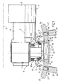
- Number 1 in Figure 1 indicates as a whole a wrapping wheel of a cigarette packing machine.
- Wheel 1 comprises a drum 2, which is fitted to a powered shaft (not shown) to rotate continuously at a given speed in a direction 4 (clockwise in Figure 6) about an axis 5.
- Drum 2 comprises a number of peripheral conveying and wrapping units (or even only one conveying and wrapping unit), only one of which is shown and indicated 6 in Figure 1.
- Unit 6 extends radially outwards, is fed by wheel 1 in direction 4, and comprises a frame 7 extending radially outwards from the periphery of drum 2 and fitted on the inner end with a shaft 8, which is fitted in rotary manner through drum 2 and oscillated, with respect to drum 2 and about an axis 9 parallel to axis 5, by a known cam actuating device (not shown).
- Unit 6 comprises a substantially U-shaped seat 10 fitted to a free end of respective frame 7 and having a concavity facing radially outwards.
- Seat 10 which is of known type, comprises a bottom wall 11 extending parallel to axis 9, and two lateral walls (not shown) parallel to the Figure 1 plane, and houses a substantially parallelepipedal, substantially rectangular-section group 12 of cigarettes 13.
- group 12 is enclosed in a tubular wrapping 14 having a longitudinal axis 15 and comprising two tubular end portions 16, each of which projects axially beyond a respective end surface 17 of group 12 and comprises two parallel minor walls 18 and two parallel major walls 19 perpendicular to walls 18.
- axis 15 of wrapping 14 is parallel to axis 9; one of walls 18 - hereinafter indicated 18a - is located at the front in direction 4; and the other wall 18 - hereinafter indicated 18b - is located at the rear in direction 4.
- unit 6 comprises a gripping device 20, which cooperates with bottom wall 11 and with the lateral walls (not shown) of seat 10 to retain group 12 inside seat 10.
- Gripping device 20 in turn comprises two jaws 21, each of which comprises a gripping head 22 and a curved rod 23, which is hinged to the free end of frame 7 and oscillated - with respect to frame 7 and by a known actuating device 20a with cam-controlled rods (not shown) - about a pin 24, crosswise to axis 9 and perpendicular to the Figure 1 plane, to and from a position gripping respective group 12 against wall 11.
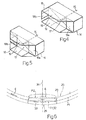
- wheel 1 feeds group 12 in direction 4, and therefore feeds each end surface 17 along a respective annular path P1 ( Figure 6), which extends in a plane 25 coincident with the Figure 6 plane and crosswise to walls 18 of relative tubular portion 16, and through a folding station 26.
- wheel 1 also comprises two folding devices 27 located at folding station 26 and each comprising a respective star-shaped wheel 28, which has a substantially truncated-cone-shaped outer surface 29 tangent to relative path P1, and is of a thickness - measured parallel to a respective generating line - approximately equal to but no greater than the distance between major walls 19 of wrapping 14. It should be pointed out that, for producing the outer wrappings of soft packs of cigarettes, for example, wheel 1 may comprise only one folding device 27.
- each wheel 28 comprises a central hub 30, which is fitted to an output shaft 31 of a known actuating device 32 for rotating wheel 28 in a direction 33 (clockwise in Figure 6) about an axis 34 of shaft 31. More specifically, and as shown in Figure 1, axis 34 is so oriented as to converge towards relative plane 25 and towards the axis 34 of the other device 27.
- Each wheel 28 also comprises three substantially boot-shaped folding members 35 equally spaced about axis 34.
- Each folding member 35 comprises an arm 36 extending radially outwards from hub 30; and a folding head 37, which is integral with the free end of arm 36, and is defined by an end surface 38 forming part of outer surface 29 of wheel 28, and by two lateral surfaces, one of which is located to the front in direction 33 and hereinafter indicated 39, and the other of which is located to the rear in direction 33 and hereinafter indicated 40.
- Surface 40 extends in a substantially radial direction with respect to hub 30, while surface 39 extends in a direction substantially crosswise to surface 40, and is connected to surface 38 by a plowshare-shaped tip 41.
- each head 37 travels along a relative path P2 tangent to relative path P1. Because of the orientation of axis 34 with respect to relative plane 25, the projection of circular path P2 in plane 25 is an elongated ellipse A, which extends inside relative path P1 and has a portion T2 substantially coincident with a portion T1 of relative path P1.
- a wheel 1 comprising one seat 10 housing a group 12 of cigarettes 13 having a tubular wrapping 14, of which is considered only one tubular portion 16 cooperating with relative folding device 27.
- wheel 1 feeds seat 10 to folding station 26 where wheel 1 comprises a plate 42 ( Figure 1) coaxial with axis 5 and defining, together with bottom wall 11, a channel 43 for the passage of group 12.
- wheel 1 comprises a plate 42 ( Figure 1) coaxial with axis 5 and defining, together with bottom wall 11, a channel 43 for the passage of group 12.
- the two jaws 21 may therefore be moved into an open position, and plate 42 cooperates with wall 11 and with said lateral walls (not shown) of seat 10 to retain group 12 firmly inside seat 10.
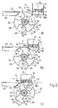
- Actuating device 32 of the folding device 27 considered is activated in time with conveying and wrapping unit 6 at the input of station 26, so as to bring the free edge of wall 18a of the tubular portion 16 considered into contact with the free edge of surface 40 of a relative folding member 35 ( Figure 2a).
- Device 32 is a variable-speed device for imparting a variable angular speed to wheel 28 and, hence, a variable linear speed to each head 37. More specifically, when the free edge of wall 18a is positioned contacting the free edge of surface 40 of relative folding member 35, the linear speed of relative head 37 is so controlled as to be less than the speed of seat 10 and so enable wrapping 14 to move over folding member 35, and folding member 35 to fold wall 18a onto relative end surface 17.
- the linear speed of folding member 35 is also so controlled as to keep said free edge of folding member 35 permanently contacting the free edge of wall 18a, and so substantially prevent any relative slide between folding member 35 and wall 18a ( Figures 2b and 2c).
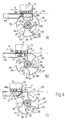
- wall 18a of wrapping 14 is maintained contacting relative end surface 17 ( Figure 3a) by a retaining plate 44 tangent to plane 25 and extending along a portion of path P1 from the output of station 26.
- wheel 28 is accelerated by device 32 to a speed greater than that of seat 10 to enable the next folding member 35, following the folding member 35 which has just folded wall 18a, to catch up with seat 10 and bring surface 39, in particular tip 41, into contact with wall 18b of wrapping 14 (Figure 3a)
- the linear speed of relative head 37 is then so controlled further as to be greater than the speed of seat 10 and so enable the folding member 35 considered to move over wrapping 14 and fold wall 18b (Figure 3b) onto relative end surface 17.
- wheel 1 may be step-operated; in which case, folding members 35 of wheel 28 act on walls 18a and 18b in the course of rotation steps of wheel 1.
Landscapes
- Engineering & Computer Science (AREA)
- Mechanical Engineering (AREA)
- Wrapping Of Specific Fragile Articles (AREA)
Claims (11)
- Roue d'enveloppement (1) d'une machine d'emballage de cigarettes ;
la roue d'enveloppement (1) comporte un premier axe (5) de rotation qui comprend au moins un siège (10) pour un groupe respectif (12) de cigarettes (13) logé dans une enveloppe tubulaire respective (14) orientée au moyen d'un deuxième axe longitudinal respectif (15) parallèle audit premier axe (5) et comportant au moins une partie d'extrémité tubulaire (16), qui fait saillie de manière axiale au-delà d'une surface d'extrémité respective (17) dudit groupe (12) et comprend deux parois parallèles (18) ;
la roue d'enveloppement (1) est montée pour tourner autour dudit premier axe (5) afin de mettre en mouvement ladite surface d'extrémité (17) à une première vitesse et dans un premier sens donné (4) le long d'un premier chemin annulaire correspondant (P1) perpendiculaire aux dites deux parois (18) et s'étendant dans un plan correspondant (25) autour du premier axe (5) ;
la roue d'enveloppement (1) comprend un moyen de pliage (27) pour plier lesdites deux parois (18) de ladite partie d'extrémité tubulaire (16) sur ladite surface d'extrémité correspondante (17) ; où le moyen de pliage (27) comprend au moins un dispositif de pliage (27), qui comporte une surface externe (29) tangente à un dit premier chemin correspondant (P1) et comprend au moins un élément de pliage (35), et un moyen d'actionnement (32) pour déplacer l'élément de pliage (35) dans un deuxième sens donné (33) le long d'un deuxième chemin annulaire (P2) ;
la roue d'enveloppement (1) est caractérisée en ce que le deuxième chemin (P2) est un chemin circulaire autour d'un troisième axe (34) convergeant vers ledit premier axe (5) et une saillie du deuxième chemin (P2) dans ledit plan correspondant (25) comprend une partie (T2) coïncidant essentiellement avec une partie (T1) du premier chemin (P1). - Roue d'enveloppement selon la revendication 1, dans laquelle chacune desdites enveloppes tubulaires (14) comprend deux parties d'extrémité tubulaires (16), dont chacune fait saillie de manière axiale au-delà de la surface d'extrémité correspondante (17) du groupe correspondant (12) et comprend deux parois parallèles (18) ; ledit moyen de pliage (27) comprend deux dits dispositifs de pliage (27), dont chacun comporte une surface externe (29) tangente à un dit premier chemin correspondant (P1) et comprend au moins un élément de pliage (35), et un moyen d'actionnement (32) pour déplacer l'élément de pliage (35) dans un deuxième sens donné (33) le long dudit deuxième chemin annulaire (P2), dont une saillie dans ledit plan correspondant (25) comprend une partie (T2) coïncidant essentiellement avec une partie (T1) du premier chemin (P1).
- Roue d'enveloppement selon la revendication 2, dans laquelle chacun desdits deuxièmes chemins (P2) est un chemin circulaire s'étendant autour d'un troisième axe (34) de rotation respectif .
- Roue d'enveloppement selon la revendication 3, dans laquelle lesdits troisièmes axes (34) convergent les uns vers les autres et vers ledit premier axe (5).
- Roue d'enveloppement selon l'une quelconque des revendications 1 à 4, dans laquelle chacune desdites surfaces externes (29) est une surface conique tronquée comportant un troisième axe (34) convergeant vers ledit plan correspondant (25) et vers ledit premier axe (5).
- Roue d'enveloppement selon l'une quelconque des revendications 1 à 5, dans laquelle ladite saillie présente essentiellement la forme d'une ellipse (A).
- Roue d'enveloppement selon l'une quelconque des revendications 3 à 6, dans laquelle ledit dispositif de pliage (27) comprend un moyeu central (30) relié audit moyen d'actionnement correspondant (32) pour tourner autour du troisième axe correspondant (34) ; et ledit élément de pliage (35) est essentiellement en forme de botte et comprend un bras (36) s'étendant de manière radiale à partir dudit moyeu (30), et une tête de pliage (37) faisant partie intégrante d'une extrémité libre dudit bras (36) et définie par une première surface d'extrémité (38) faisant partie de ladite surface externe (29), et par une deuxième et une troisième surface latérale (40, 39) situées respectivement à l'arrière et à l'avant dans ledit deuxième sens (33), et pour engager respectivement une première (18a) desdites parois (18), située à l'avant dans ledit premier sens (4), et une deuxième (18b) desdites parois (18), située à l'arrière dans ledit premier sens (4).
- Roue d'enveloppement selon la revendication 7, dans laquelle ladite deuxième surface latérale (40) s'étend dans un sens essentiellement radial par rapport audit moyeu (30) ; et où ladite troisième surface latérale (30) s'étend dans un sens essentiellement perpendiculaire à ladite deuxième surface latérale (40).
- Roue d'enveloppement selon la revendication 7 ou 8, dans laquelle chacun desdits dispositifs de pliage (27) comprend une roue étoilée de forme conique tronquée (28) tour à tour comprenant ledit moyeu (30) et au moins deux dits éléments de pliage (35) s'étendant vers l'extérieur à partir dudit moyeu (30).
- Roue d'enveloppement selon la revendication 9, dans laquelle lesdits éléments de pliage (35) sont au nombre de trois et espacés d'une distance égale autour dudit troisième axe (34).
- Roue d'enveloppement selon l'une quelconque des revendications 1 à 10, dans laquelle lesdits moyens d'actionnement (32) sont des moyens d'actionnement à vitesse variable pour donner à chacun desdits dispositifs de pliage (27) une deuxième vitesse qui est inférieure à ladite première vitesse lors d'un pliage d'une première (18a) desdites parois (18) située à l'avant dans ledit premier sens (4), et est supérieure à ladite première vitesse lors d'un pliage d'une deuxième (18b) desdites parois (18) située à l'arrière dans ledit premier sens (4).
Applications Claiming Priority (2)
| Application Number | Priority Date | Filing Date | Title |
|---|---|---|---|
| ITBO990303 | 1999-06-03 | ||
| IT1999BO000303A IT1309280B1 (it) | 1999-06-03 | 1999-06-03 | Ruota di incarto di una macchina impacchettatrice di sigarette. |
Publications (2)
| Publication Number | Publication Date |
|---|---|
| EP1057726A1 EP1057726A1 (fr) | 2000-12-06 |
| EP1057726B1 true EP1057726B1 (fr) | 2006-03-01 |
Family
ID=11344032
Family Applications (1)
| Application Number | Title | Priority Date | Filing Date |
|---|---|---|---|
| EP00112024A Expired - Lifetime EP1057726B1 (fr) | 1999-06-03 | 2000-06-02 | Roue d'enveloppement pour machine d'emballage de cigarettes |
Country Status (6)
| Country | Link |
|---|---|
| US (1) | US6381921B1 (fr) |
| EP (1) | EP1057726B1 (fr) |
| CN (1) | CN1195660C (fr) |
| DE (1) | DE60026200T2 (fr) |
| IT (1) | IT1309280B1 (fr) |
| RU (1) | RU2245827C2 (fr) |
Families Citing this family (6)
| Publication number | Priority date | Publication date | Assignee | Title |
|---|---|---|---|---|
| EP1316999A1 (fr) | 2001-11-28 | 2003-06-04 | Continental ISAD Electronic Systems GmbH & Co. oHG | Procédé et dispositif pour contacter des composants électroniques de puissance |
| ITBO20040498A1 (it) * | 2004-08-03 | 2004-11-03 | Azionaria Costruzioni Acma Spa | Dispositivo per la piegatura di coperchi di pacchetti rigidi in macchine per il confezionamento di detti pacchetti e macchina incorporante tale dispositivo |
| US7032359B1 (en) | 2004-11-29 | 2006-04-25 | Advanced Dynamics Corporation Ltd. | Roll wrap crimper |
| ITBO20080264A1 (it) * | 2008-04-24 | 2009-10-25 | Gima Spa | Apparato di avvolgimento e chiusura di un involucro attorno ad un articolo. |
| DE102011018839A1 (de) * | 2011-04-27 | 2012-10-31 | Winkler + Dünnebier Gmbh | Verfahren zum Verpacken von Produkten und Verpackungsanlage zur Durchführung des Verfahrens |
| ITBO20110631A1 (it) * | 2011-11-07 | 2013-05-08 | Gd Spa | Metodo di incarto per applicare un sovraincarto termosaldabile ad una confezione di articoli da fumo con apertura a scorrimento e con coperchio incernierato. |
Family Cites Families (10)
| Publication number | Priority date | Publication date | Assignee | Title |
|---|---|---|---|---|
| US2599393A (en) * | 1950-12-01 | 1952-06-03 | Bemis Bro Bag Co | Bag supporting means for bag closing and sealing machines |
| US2911779A (en) * | 1957-01-17 | 1959-11-10 | Package Machinery Co | Tucking mechanism for wrapping machines |
| US3269092A (en) * | 1963-08-23 | 1966-08-30 | St Regis Paper Co | Apparatus for closing bag tops and the like |
| US3602107A (en) * | 1969-06-20 | 1971-08-31 | Riegel Paper Corp | Carton flap folder |
| IT1028910B (it) * | 1975-03-07 | 1979-02-10 | Amf Sasib | Dispositivo piegatore d involucri in particolare per macchine impacchettatrici di sigarette |
| US4539002A (en) * | 1982-07-23 | 1985-09-03 | Post Machinery Company, Inc. | Control apparatus for trailing edge folder in carton folding machine |
| DD279451A1 (de) * | 1989-01-20 | 1990-06-06 | Nagema Veb K | Vorrichtung zur herstellung einer seitenfaltung |
| IT1252457B (it) * | 1991-07-29 | 1995-06-16 | Gd Spa | Dispositivo per la saldatura di involucri in macchine incartatrici e/o sovraincartatrici di prodotti, in particolare di pacchetti di sigarette |
| IT1285922B1 (it) * | 1996-05-06 | 1998-06-26 | Gd Spa | Metodo e dispositivo per la piegatura di lembi di estremita' di involucri tubolari |
| IT1304028B1 (it) * | 1998-07-08 | 2001-03-02 | Gd Spa | Metodo e macchina per l'incarto di un prodotto in un foglio di incartodi materiale termosaldabile. |
-
1999
- 1999-06-03 IT IT1999BO000303A patent/IT1309280B1/it active
-
2000
- 2000-06-02 RU RU2000114204/12A patent/RU2245827C2/ru not_active IP Right Cessation
- 2000-06-02 DE DE60026200T patent/DE60026200T2/de not_active Expired - Fee Related
- 2000-06-02 CN CNB001087762A patent/CN1195660C/zh not_active Expired - Fee Related
- 2000-06-02 EP EP00112024A patent/EP1057726B1/fr not_active Expired - Lifetime
- 2000-06-02 US US09/586,244 patent/US6381921B1/en not_active Expired - Fee Related
Also Published As
| Publication number | Publication date |
|---|---|
| EP1057726A1 (fr) | 2000-12-06 |
| DE60026200D1 (de) | 2006-04-27 |
| IT1309280B1 (it) | 2002-01-22 |
| US6381921B1 (en) | 2002-05-07 |
| CN1276322A (zh) | 2000-12-13 |
| ITBO990303A0 (it) | 1999-06-03 |
| DE60026200T2 (de) | 2006-11-23 |
| CN1195660C (zh) | 2005-04-06 |
| ITBO990303A1 (it) | 2000-12-03 |
| RU2245827C2 (ru) | 2005-02-10 |
Similar Documents
| Publication | Publication Date | Title |
|---|---|---|
| US5003755A (en) | Method and device for producing tubular wrappings | |
| US5275275A (en) | Method of transferring products between continuously-moving conveyors | |
| KR102586941B1 (ko) | 담배 제품들의 2 개의 구분된 그룹들을 포함하는 담배 제품들의 패킷을 제조하는 래핑 방법 및 포장 기계 | |
| EP0970885B1 (fr) | Dispositif pour amener des ébauches à une machine d'emballage | |
| US4144695A (en) | Device for folding the head portions of inner wrappers in a machine for packeting cigarettes into hinged-lid type packets | |
| EP1057726B1 (fr) | Roue d'enveloppement pour machine d'emballage de cigarettes | |
| US3968627A (en) | Twist finger device for a candy wrapping machine | |
| US6286291B1 (en) | Method and machine for wrapping a product | |
| US5771666A (en) | Method of continuously wrapping products | |
| US6189296B1 (en) | Method and machine for packing a product | |
| GB2277507A (en) | Folding apparatus for folding wrappers around articles | |
| EP0792807B1 (fr) | Procédé et dispositif de pliage de feuilles d'emballage le long de lignes de pliage préformées | |
| CN112292328B (zh) | 用于形成双包装的领口的设备和用于形成双包装的包装线 | |
| EP0769453B1 (fr) | Procédé continu pour envelopper des produits | |
| US5246098A (en) | Output conveyor unit for rigid hinged-lid cigarette packing machines | |
| US5694738A (en) | Body flap folding apparatus in packaging machine | |
| US6513533B2 (en) | Method for forming tubular wrappings on a cigarette packing machine | |
| US6601369B2 (en) | Method and unit for closing the ends of tubular wrappings on a cigarette packing machine | |
| EP1531127B1 (fr) | Procédé et dispositif pour la formation d'une enveloppe tubulaire | |
| ITBO980076A1 (it) | Metodo per il trasferimento di articoli. | |
| EP1748942B1 (fr) | Procede et tambour d'emballage de produits pour machine de conditionnement | |
| JPH08217005A (ja) | 包装機の胴折り込み装置におけるフラップ保持装置 | |
| EP1497179B1 (fr) | Procede et dispositif permettant de former des groupes d'emballages d'un produit alimentaire pateux |
Legal Events
| Date | Code | Title | Description |
|---|---|---|---|
| PUAI | Public reference made under article 153(3) epc to a published international application that has entered the european phase |
Free format text: ORIGINAL CODE: 0009012 |
|
| AK | Designated contracting states |
Kind code of ref document: A1 Designated state(s): DE FR GB IT |
|
| AX | Request for extension of the european patent |
Free format text: AL;LT;LV;MK;RO;SI |
|
| 17P | Request for examination filed |
Effective date: 20010529 |
|
| AKX | Designation fees paid |
Free format text: DE FR GB IT |
|
| RAP1 | Party data changed (applicant data changed or rights of an application transferred) |
Owner name: G.D SOCIETA' PER AZIONI |
|
| 17Q | First examination report despatched |
Effective date: 20050509 |
|
| GRAP | Despatch of communication of intention to grant a patent |
Free format text: ORIGINAL CODE: EPIDOSNIGR1 |
|
| GRAS | Grant fee paid |
Free format text: ORIGINAL CODE: EPIDOSNIGR3 |
|
| GRAA | (expected) grant |
Free format text: ORIGINAL CODE: 0009210 |
|
| AK | Designated contracting states |
Kind code of ref document: B1 Designated state(s): DE FR GB IT |
|
| REG | Reference to a national code |
Ref country code: GB Ref legal event code: FG4D |
|
| REF | Corresponds to: |
Ref document number: 60026200 Country of ref document: DE Date of ref document: 20060427 Kind code of ref document: P |
|
| PGFP | Annual fee paid to national office [announced via postgrant information from national office to epo] |
Ref country code: IT Payment date: 20060630 Year of fee payment: 7 |
|
| ET | Fr: translation filed | ||
| PLBE | No opposition filed within time limit |
Free format text: ORIGINAL CODE: 0009261 |
|
| STAA | Information on the status of an ep patent application or granted ep patent |
Free format text: STATUS: NO OPPOSITION FILED WITHIN TIME LIMIT |
|
| 26N | No opposition filed |
Effective date: 20061204 |
|
| PGFP | Annual fee paid to national office [announced via postgrant information from national office to epo] |
Ref country code: FR Payment date: 20090617 Year of fee payment: 10 |
|
| PG25 | Lapsed in a contracting state [announced via postgrant information from national office to epo] |
Ref country code: IT Free format text: LAPSE BECAUSE OF NON-PAYMENT OF DUE FEES Effective date: 20070602 |
|
| PGFP | Annual fee paid to national office [announced via postgrant information from national office to epo] |
Ref country code: GB Payment date: 20090625 Year of fee payment: 10 Ref country code: DE Payment date: 20090629 Year of fee payment: 10 |
|
| GBPC | Gb: european patent ceased through non-payment of renewal fee |
Effective date: 20100602 |
|
| REG | Reference to a national code |
Ref country code: FR Ref legal event code: ST Effective date: 20110228 |
|
| PG25 | Lapsed in a contracting state [announced via postgrant information from national office to epo] |
Ref country code: DE Free format text: LAPSE BECAUSE OF NON-PAYMENT OF DUE FEES Effective date: 20110101 |
|
| PG25 | Lapsed in a contracting state [announced via postgrant information from national office to epo] |
Ref country code: FR Free format text: LAPSE BECAUSE OF NON-PAYMENT OF DUE FEES Effective date: 20100630 |
|
| PG25 | Lapsed in a contracting state [announced via postgrant information from national office to epo] |
Ref country code: GB Free format text: LAPSE BECAUSE OF NON-PAYMENT OF DUE FEES Effective date: 20100602 |