EP1057760A2 - Appareil pour alimenter des feuilles - Google Patents
Appareil pour alimenter des feuilles Download PDFInfo
- Publication number
- EP1057760A2 EP1057760A2 EP00304492A EP00304492A EP1057760A2 EP 1057760 A2 EP1057760 A2 EP 1057760A2 EP 00304492 A EP00304492 A EP 00304492A EP 00304492 A EP00304492 A EP 00304492A EP 1057760 A2 EP1057760 A2 EP 1057760A2
- Authority
- EP
- European Patent Office
- Prior art keywords
- sheet supply
- adjusting
- rotationally
- separating
- urging
- Prior art date
- Legal status (The legal status is an assumption and is not a legal conclusion. Google has not performed a legal analysis and makes no representation as to the accuracy of the status listed.)
- Granted
Links
Images


Classifications
-
- B—PERFORMING OPERATIONS; TRANSPORTING
- B65—CONVEYING; PACKING; STORING; HANDLING THIN OR FILAMENTARY MATERIAL
- B65H—HANDLING THIN OR FILAMENTARY MATERIAL, e.g. SHEETS, WEBS, CABLES
- B65H3/00—Separating articles from piles
- B65H3/46—Supplementary devices or measures to assist separation or prevent double feed
- B65H3/52—Friction retainers acting on under or rear side of article being separated
- B65H3/5207—Non-driven retainers, e.g. movable retainers being moved by the motion of the article
- B65H3/5215—Non-driven retainers, e.g. movable retainers being moved by the motion of the article the retainers positioned under articles separated from the top of the pile
- B65H3/5223—Retainers of the pad-type, e.g. friction pads
-
- B—PERFORMING OPERATIONS; TRANSPORTING
- B65—CONVEYING; PACKING; STORING; HANDLING THIN OR FILAMENTARY MATERIAL
- B65H—HANDLING THIN OR FILAMENTARY MATERIAL, e.g. SHEETS, WEBS, CABLES
- B65H2515/00—Physical entities not provided for in groups B65H2511/00 or B65H2513/00
- B65H2515/30—Forces; Stresses
- B65H2515/34—Pressure, e.g. fluid pressure
Definitions
- the present invention relates to a sheet supply apparatus of a so-called frictional separating method type.
- the sheet supply apparatus of such type can separate a sheet from sheets stacked therein by utilizing friction between a sheet supply roller and a separating plate.
- a sheet supply apparatus is such a machine that separates and feeds out stacked sheets one by one.
- Such sheet supply apparatus is usually installed in a printing machine, for example.
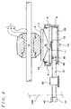
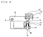
- FIGS. 8 to 10 illustrate one example of such conventional sheet supply apparatus.
- the sheet supply apparatus includes a sheet supply roller 1 and a separating base 2.
- the sheet supply roller 1, a separating member, is situated to a predetermined position and driven to rotate.
- the separating base 2, a separating member, is situated below the sheet supply roller 1.
- the sheet supply roller 1 includes a core 3 and a roller member 4 integrally connected to an outer circumferential surface of the core 3.
- the core 3 is connected to a sheet supply shaft 5.
- the sheet supply shaft 5 is connected to a not-shown drive shaft.
- the separating base 2 includes a high-friction member 6 and a curved stainless plate member 7 situated to a sheet-entrance side of the base.
- the sheet supply roller 1 contacts the high-friction member 6 of the separating base 2. Sheets fed thereto are separated from each other so that only one of the sheets can be conveyed forward.
- a supporting plate 8 is fixed to a predetermined position.
- a lever 10 is pivotally movably attached to the supporting plate 8 by a support screw 9.
- the separating base 2 is attached to the lever 10 by a pin 11 so as to rotate around the pin.
- the separating base 2 can be detached from the pin 11.
- the supporting plate 8 has an attachment plate 12 integrally formed therewith. Through holes 8a and 12a are formed in a bottom of the supporting plate 8 and the attachment plate 12, respectively.
- a pressing pole 13 as a pressing member is inserted through the through holes 8a and 12a.
- the pressing pole 13 can move vertically along an axial direction of itself.
- a flange 14 is attached to the pressing pole 13 between the bottom of the supporting plate 8 and the attachment plate 12.
- An adjusting plate 15 as adjusting means is slidably situated on an upper surface of the bottom of the supporting plate 8.
- the adjusting plate 15 is longitudinal in a sliding direction of itself and narrow in a width direction.
- a slit 16 is formed in the adjusting plate 15 along the longitudinal direction thereof.
- the pressing pole 13 is inserted through the slit.
- An operating surface 17 is formed on both sides of the slit 16 on an upper surface of the adjusting plate 15.
- One end portion of the adjusting plate 15 is designated as an operating end 18 and situated inside a casing of the present sheet supply apparatus.
- a spring 19 as urging means is disposed around the pressing pole 13 between the flange 14 and the adjusting plate 15.
- the printing sheet may not be conveyed, or a plurality of the printing sheets is conveyed while not being separated from each other.
- the former phenomenon is called “conveyance failure", and the latter "multiple conveyance”.
- the adjusting means explained above is used to properly arrange the difference among the frictional forces.
- the surface of the printing sheet is rough because it is composed of intertwined fibers.
- the frictional force between the sheet supply roller 1 and the printing sheet is enlarged and stabilized. If the nip width is small, the frictional force tends to decrease due to surface abrasion of the sheet supply roller 1 and paper powder generated from the printing sheets. Since many types of the printing sheets are in use, the frictional force among the sheets is varied accordingly. Therefore, stable conveyance of the printing sheet of many types inevitably requires the above-explained adjusting means for adjusting separating pressure.
- the separating pressure is to be adjusted by users so as to conform to a type of the sheet to be used.
- the pressing pole 13 is elastically urged upward by the spring 19 relative to the supporting plate 8. A top end of the pressing pole 13 presses up the lever 10. The separating base 2 attached to the lever 10 is urged upward to contact the sheet supply roller 1.
- the separating pressure exerted on the sheet supply roller 1 by the separating base 2 can be adjusted by operating the adjusting plate 15.
- a user is to detach a part of a casing of the present apparatus to expose the operating end 18.
- the user is to take the operating end 18 and pull the adjusting plate 15 to slide along the longitudinal direction thereof.
- the height of the operating surface 17 of the adjusting plate 15 is changed at a position where the spring 19 is disposed.
- FIGS. 8 and 10 show that the spring 19 is supported by a relatively low operating surface 17, which means the separating pressure is small.
- FIG. 9 shows that the spring 19 is supported by a relatively high operating surface 17, which means the separating pressure is large.
- the part is attached to the casing, and then the sheet supply apparatus is actually operated to feed the printing sheets, so that effect of adjusting the separating pressure is confirmed. If no effect is confirmed, the part of the casing is again detached and the adjustment is conducted once more.
- the adjusting plate 15 is required to be made in a longitudinal form along the sliding direction. Additionally, any other parts or members can not be allowed to be placed in a space where the adjusting plate 15 slides so as to prevent interference therewith. Thus, in the conventional sheet supply apparatus, an inside space thereof is not utilized effectively.
- the slidable adjusting plate 15 is downsized to its limit so as to utilize any of the inside space. Accordingly, the operating end 18 of the adjusting plate 15 must be placed inside the apparatus. This means that the operating end 18 cannot project out the apparatus. Therefore, when adjustment of the separating pressure is needed, the casing must be opened by detaching the part therefrom.
- An object of the present invention is to provide a sheet supply apparatus which is enough compact to be situated in a small space and can be easily operated from the outside thereof.
- a sheet supply apparatus comprising a sheet supply member for supplying printing sheets; a separating member movably situated adjacent to the sheet supply member; a pressing member movably situated adjacent to the separating member; urging device disposed near the pressing member for urging the pressing member toward the separating member so that the separating member contacts the sheet supply member, and adjusting device connected to the urging device for adjusting an urging force exerted on the pressing member by the urging device, the adjusting device including a rotationally operating portion and a rotationally adjusting portion connected to the rotationally operating portion, the rotationally adjusting portion being situated adjacent to the pressing member and the urging member and adjusting the urging force while being operated by the rotationally operating portion.
- a sheet supply apparatus comprising a sheet supply roller for supplying printing sheets; a separating member pivotally movably situated adjacent to the sheet supply roller; a pressing member movably situated adjacent to the separating member for pressing the separating member toward the sheet supply roller; operating portion pivotally movably situated adjacent to the pressing member; urging device situated between the pressing member and the operating portion, the urging device urging the pressing member toward the separating member; rotationally adjusting portion cooperating with the operating portion, the rotationally adjusting portion moving the operating portion while being rotated so that an urging force exerted on the separating member by the urging device through the pressing member is adjusted; and a rotationally operating portion connected to the rotationally adjusting portion for rotating the rotationally adjusting portion.
- a sheet supply apparatus comprising a sheet supply roller for supplying printing sheets; a separating member pivotally movably situated adjacent to the sheet supply roller; a pressing member movably situated adjacent to the separating member for pressing the separating member toward the sheet supply roller; a cam rotatably situated adjacent to the pressing member; urging device situated between the pressing member and the cam, the urging device urging the pressing member toward the separating member; and a rotationally operating portion connected to the cam for rotating the cam so that an urging force exerted on the separating member by the urging device through the pressing member is adjusted.
- a sheet supply apparatus as defined in a fourth aspect of the present invention in the second aspect of the present invention, further comprises a case containing the sheet supply roller and the separating member therein, and the rotationally operating portion is operated from an outside of the case.
- a sheet supply apparatus as defined in a fifth aspect of the present invention in the second aspect of the present invention, further comprises fixing device situated at the rotationally operating portion, and the fixing means fixes the rotationally operating portion to an optional position in a rotational direction thereof.
- a sheet supply apparatus as defined in a sixth aspect of the present invention in the third aspect of the present invention, further comprises a case containing the sheet supply roller and the separating member therein, and the rotationally operating portion is operated from an outside of the case.
- a sheet supply apparatus as defined in a seventh aspect of the present invention in the third aspect of the present invention, further comprises fixing device situated at the rotationally operating portion, and the fixing device fixes the rotationally operating portion to an optional position in a rotational direction thereof.
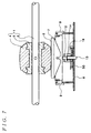
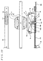
- Figs. 1 to 3 show a first embodiment of a sheet supply apparatus of the present invention.
- the sheet supply apparatus includes a sheet supply roller 1 situated to a predetermined position as a sheet supply member and a separating base 2 situated below the sheet supply roller 1 as a separating member.
- the separating base 2 has a high-friction member 6 and a curved stainless plate member 7 situated to an entrance side of a printing sheet.
- the sheet supply roller 1 contacts the high-friction member 6 of the separating base 2. Sheets fed thereto are separated from each other so that only one of the sheets can be conveyed forward.
- the sheet supply roller 1 includes a core 3 and a roller member 4 integrally connected to an outer circumferential surface of the core 3.
- the core 3 is connected to a sheet supply shaft 5.
- the sheet supply shaft 5 is connected to a not-shown drive shaft.
- a supporting plate 8 is fixed to a predetermined position.
- a lever 10 is pivotally movably attached to the supporting plate 8 by a support screw 9.
- the separating base 2 is attached to the lever 10 by a pin 11 so as to be rotationally movable around the pin 11.
- the separating base 2 can be detached from the pin 11.
- the supporting plate 8 has an attachment plate 12 integrally formed therewith.
- An operating plate 20 as an operating portion is attached to the supporting plate 8 by the support screw 9.
- a forward end portion of the operating plate 20 protrudes over each of forward end portions of the supporting plate 8 and the separating base 2.
- the operating plate 20 and the separating base 2 are rotationally movable relative to the supporting plate 8 in an independent manner with each other.
- Through holes 8a, 20a, and 12a are formed in a bottom of the supporting plate 8, a forward portion of the operating plate 20, and the attachment plate 12, respectively.
- a pressing pole 13 as a pressing member is inserted through the through holes 8a, 20a, and 12a.
- the pressing pole 13 can move axially vertically.
- a flange 14 is attached to an upper portion of the pressing pole 13 between the operating plate 20 and the attachment plate 12.
- a spring 19 as urging means is fitted on the pressing pole 13 between the flange 14 and the attachment plate 12. The spring 19 urges the pressing pole 13 toward the separating base 2.
- the sheet supply apparatus includes adjusting means for adjusting the urging force of the spring 19.
- the adjusting means includes a rotationally adjusting portion 30 for pivotally moving the operating plate 20 and a rotationally operating portion 40 for operating the rotationally adjusting portion 30.
- the rotationally adjusting portion 30 has an adjusting shaft 31.
- the adjusting shaft 31 is supported by a bearing 32 situated to a predetermined position in a case 100.
- the bearing 32 applies appropriate rotational resistance to the adjusting shaft 31 so that the adjusting shaft 31 can be optionally positioned in a rotational direction.
- a pin 33 is attached to a circumferential surface of one end of the adjusting shaft 31.
- the pin 33 can contact the operating plate 20. Accordingly, if the adjusting shaft 31 is rotated, the pin 33 moves the operating plate 20.
- the other end of the adjusting shaft 31 protrudes outside the case 100 of the apparatus.
- an adjusting knob 41 is attached as the rotationally operating portion.
- the pressing pole 13 is urged upward relative to the supporting plate 8 by elasticity of the spring 19.
- the top end of the pressing pole 13 pushes up the lever 10.
- the separating base 2 attached to the lever 10 is urged upward to contact the sheet supply roller 1.
- Figs. 1 and 3 illustrate a condition where the operating plate 20 is positioned low and the separating pressure is small.
- Fig. 2 illustrates a condition where the operating plate 20 is positioned high and the separating pressure is large.
- the sheet supply apparatus is operated to feed printing sheets actually, so that whether the adjustment of the separating pressure is satisfactory can be confirmed. If not, the adjusting knob 41 can be operated outside the apparatus. It is not necessary to detach a part of the case and operate the inside mechanism.
- the separating pressure acting between the sheet supply roller 1 and the separating base 2 is determined by the urging force of the pressing pole 13, and the urging force is adjusted by the operating plate 20 moved by the pin 33 of the rotating adjusting shaft 31. Therefore, in comparison with the conventional adjustment mechanism with the sliding longitudinal cam plate, the adjusting means of the present embodiment occupies smaller space inside the apparatus. Additionally, operation of the present apparatus is convenient since it can be conducted from outside of the case 100 by the adjusting knob 41.
- Figs. 4 to 7 illustrate a second embodiment of the sheet supply apparatus of the present invention.
- This sheet supply apparatus has adjusting means structurally different from that of the first embodiment. Substantially the same portions as that of the first embodiment will be referred to by the reference numerals of Figs 1 to 3, and explanation thereof may be omitted.
- the adjusting means of the present embodiment includes a cam 50 of a disc-form as the rotationally adjusting portion for adjusting the urging force of the spring 19.
- a supporting shaft 51 is formed on the upper surface of the supporting plate 8.
- the supporting shaft 51 is inserted into a supporting hole formed in the center of the cam 50 so that the cam 50 can rotate relative to the supporting plate 8.
- the cam 50 has a groove 52 circumferentially formed in an upper surface thereof.
- an operating surface 53 is formed on the upper surface of the cam 50 along the groove 52 for operating the pressing pole 13. The height of the operating surface 53, a thickness of the cam 50, changes gradually along the circumferential direction of the cam.
- the pressing pole 13 is inserted through the groove 52.
- the pressing pole 13 is axially vertically movable.
- a flange 14 is attached to an upper portion of the pressing pole 13 between the cam 50 and the attachment plate 12.
- a spring 19 as urging means is fitted on the pressing pole 13 between the flange 14 and the cam 50.
- a washer 54 as receiving means is situated between the lower end of the spring 19 and the cam 50.
- the spring 19 urges the pressing pole 13 toward the separating base 2 relative to the supporting plate 8.
- An outer circumferential surface of the cam 50 is formed as a warm wheel 55.
- the warm wheel 55 engages a warm 56.
- the warm 56 is attached to one end of a warm shaft 57.
- the warm shaft 57 is rotatably supported by a not-shown bearing and protruding outside the case 100.
- an adjusting knob 60 as the rotationally operating portion is attached to the other end of the warm shaft 57 outside the case 100. Rotation of the adjusting knob 60 makes the cam 50 to rotate.
- the pressing pole 13 is urged upward relative to the supporting plate 8 by an elastic force of the spring 19.
- the top of the pressing pole 13 pushes up the lever 10.
- the separating base 2 attached to the lever 10 is urged upward to contact the sheet supplying roller 1.
- Figs. 4 and 7 illustrate a condition where the operating surface 53 for pressing the spring 19 is positioned low so that the pressing force of the spring 19 is adjusted to be small. This is the case where the separating pressure is adjusted to be small.
- Fig. 6 illustrates a condition where the operating surface 53 for pressing the spring 19 is positioned high so that the pressing force of the spring 19 is adjusted to be large. This is the case where the separating pressure is adjusted to be large.
- the sheet supply apparatus is operated to feed printing sheets actually, so that whether the adjustment of the separating pressure is satisfactory can be confirmed. If not, the adjusting knob can be operated outside the apparatus. It is not necessary to detach a part of the case and operate the inside mechanism.
- the separating pressure acting between the sheet supply roller 1 and the separating base 2 is determined by the urging force of the pressing pole 13, and which force is adjusted by the rotating cam 50. Further, the cam 50 is rotated by the warm 56 and the warm wheel 55. Therefore, in comparison with the conventional adjustment mechanism with the sliding longitudinal cam plate, the adjusting means of the present embodiment occupies smaller space inside the apparatus. Additionally, the present apparatus is convenient in use since it can be operated from outside of the case 100 by the adjusting knob 60.
- the sheet supply apparatus of the present invention as explained above can be applicable to various kinds of machines that need function of separating stacked sheets.
- the invention can be applied to a printing machine or a gathering machine for feeding printed sheets into a plurality of bins.
- the present invention in a sheet supply apparatus in which printing sheets are separated by a sheet supply member and a separating member, a force urging the separating member to contact the sheet supply member is adjusted by a rotationally adjusting portion and a rotationally operating portion associated therewith. Therefore, the present invention facilitates more effective utilization of the space inside the apparatus in comparison with the conventional adjusting member of the sliding constitution. Additionally, operation is easy in the apparatus of the present invention since it can be conducted from the outside thereof. Further, since it is not necessary to form a groove in a structural member of the apparatus for guiding the conventional adjusting member to slide therein, strength of the structural member does not deteriorate.
- the present invention can provide the sheet supply apparatus that is enough compact to be situated in a small space and includes the separating pressure adjusting mechanism that is operable from the outside thereof.
Landscapes
- Engineering & Computer Science (AREA)
- Mechanical Engineering (AREA)
- Sheets, Magazines, And Separation Thereof (AREA)
Applications Claiming Priority (2)
| Application Number | Priority Date | Filing Date | Title |
|---|---|---|---|
| JP14669699A JP3618581B2 (ja) | 1999-05-26 | 1999-05-26 | 給紙装置 |
| JP14669699 | 1999-05-26 |
Publications (3)
| Publication Number | Publication Date |
|---|---|
| EP1057760A2 true EP1057760A2 (fr) | 2000-12-06 |
| EP1057760A3 EP1057760A3 (fr) | 2002-06-26 |
| EP1057760B1 EP1057760B1 (fr) | 2005-03-09 |
Family
ID=15413501
Family Applications (1)
| Application Number | Title | Priority Date | Filing Date |
|---|---|---|---|
| EP00304492A Expired - Lifetime EP1057760B1 (fr) | 1999-05-26 | 2000-05-26 | Appareil pour alimenter des feuilles |
Country Status (4)
| Country | Link |
|---|---|
| US (1) | US6398209B1 (fr) |
| EP (1) | EP1057760B1 (fr) |
| JP (1) | JP3618581B2 (fr) |
| DE (1) | DE60018507T2 (fr) |
Families Citing this family (4)
| Publication number | Priority date | Publication date | Assignee | Title |
|---|---|---|---|---|
| JP2001233491A (ja) * | 2000-02-24 | 2001-08-28 | Murata Mach Ltd | 自動シート搬送装置 |
| DE60123712T2 (de) * | 2000-08-08 | 2007-08-16 | Ricoh Co., Ltd. | Blattzuführverfahren und Vorrichtung für eine Bilderzeugungsvorrichtung |
| US6575452B2 (en) * | 2001-04-30 | 2003-06-10 | Silitek Corporation | Mechanism for automatically and adjustably feeding sheets |
| JP4127288B2 (ja) * | 2006-04-06 | 2008-07-30 | 村田機械株式会社 | 用紙搬送装置 |
Family Cites Families (6)
| Publication number | Priority date | Publication date | Assignee | Title |
|---|---|---|---|---|
| US4674737A (en) * | 1983-09-14 | 1987-06-23 | Ricoh Company, Ltd. | Automatic sheet feeding device |
| FR2588537B1 (fr) * | 1985-10-14 | 1988-05-13 | Telephonie Ind Commerciale | Distributeur de feuilles a frottement, notamment pour copieur automatique. |
| JPH048115Y2 (fr) * | 1986-05-30 | 1992-03-02 | ||
| JPH01118938U (fr) * | 1988-01-30 | 1989-08-11 | ||
| JP3406395B2 (ja) * | 1994-08-31 | 2003-05-12 | 理想科学工業株式会社 | 給紙装置 |
| JPH11180577A (ja) * | 1997-12-19 | 1999-07-06 | Canon Inc | 付勢力調整可能な付勢力付与機構及び該機構を備えた画像形成装置 |
-
1999
- 1999-05-26 JP JP14669699A patent/JP3618581B2/ja not_active Expired - Fee Related
-
2000
- 2000-05-22 US US09/576,385 patent/US6398209B1/en not_active Expired - Fee Related
- 2000-05-26 DE DE60018507T patent/DE60018507T2/de not_active Expired - Fee Related
- 2000-05-26 EP EP00304492A patent/EP1057760B1/fr not_active Expired - Lifetime
Also Published As
| Publication number | Publication date |
|---|---|
| EP1057760A3 (fr) | 2002-06-26 |
| JP3618581B2 (ja) | 2005-02-09 |
| US6398209B1 (en) | 2002-06-04 |
| EP1057760B1 (fr) | 2005-03-09 |
| DE60018507T2 (de) | 2006-04-06 |
| JP2000335767A (ja) | 2000-12-05 |
| DE60018507D1 (de) | 2005-04-14 |
Similar Documents
| Publication | Publication Date | Title |
|---|---|---|
| US8262084B2 (en) | Sheet feeding apparatus and image forming apparatus with sheet feeding cassette and associated locking means | |
| US4437656A (en) | Sheet feeding device | |
| JP2010202287A (ja) | 給紙装置、画像形成装置 | |
| US4928951A (en) | Automatic paper feed device | |
| EP0918028B1 (fr) | Dispositif d'alimentation en feuilles | |
| US6398209B1 (en) | Sheet supply apparatus | |
| US6053491A (en) | Sheet feeder | |
| US6089562A (en) | Device for feeding a recordable paper to an image forming apparatus | |
| US7455294B2 (en) | Paper-releasing mechanism | |
| US20040041332A1 (en) | Sheet separate-feeding apparatus | |
| JP3877413B2 (ja) | 画像形成装置 | |
| US5890711A (en) | Paper feeding pressure control apparatus for ink-jet printer | |
| US7891656B1 (en) | Sheet feeding apparatus with sheet releasing mechanism | |
| US5700005A (en) | Apparatus for controlling sheet feed-out from an automatic sheet feeder into a receiving tray | |
| JP4195401B2 (ja) | 紙折り機 | |
| JP2009269696A (ja) | シート給送装置及び画像形成装置 | |
| JP3436621B2 (ja) | 給紙装置 | |
| JP2002362760A (ja) | 給紙装置 | |
| JP3400604B2 (ja) | 給紙装置 | |
| JP3238990B2 (ja) | 給紙装置及び画像形成装置 | |
| JP7746137B2 (ja) | シート給送装置 | |
| KR20050077360A (ko) | 2 가지 방식의 용지 픽업 시스템 | |
| JP3666657B2 (ja) | シート材の供給装置 | |
| JP3628506B2 (ja) | 手差し給紙装置 | |
| JP2023081541A (ja) | シート給送装置 |
Legal Events
| Date | Code | Title | Description |
|---|---|---|---|
| PUAI | Public reference made under article 153(3) epc to a published international application that has entered the european phase |
Free format text: ORIGINAL CODE: 0009012 |
|
| 17P | Request for examination filed |
Effective date: 20000615 |
|
| AK | Designated contracting states |
Kind code of ref document: A2 Designated state(s): AT BE CH CY DE DK ES FI FR GB GR IE IT LI LU MC NL PT SE |
|
| AX | Request for extension of the european patent |
Free format text: AL;LT;LV;MK;RO;SI |
|
| PUAL | Search report despatched |
Free format text: ORIGINAL CODE: 0009013 |
|
| AK | Designated contracting states |
Kind code of ref document: A3 Designated state(s): AT BE CH CY DE DK ES FI FR GB GR IE IT LI LU MC NL PT SE |
|
| AX | Request for extension of the european patent |
Free format text: AL;LT;LV;MK;RO;SI |
|
| AKX | Designation fees paid |
Designated state(s): DE FR GB |
|
| 17Q | First examination report despatched |
Effective date: 20030407 |
|
| GRAP | Despatch of communication of intention to grant a patent |
Free format text: ORIGINAL CODE: EPIDOSNIGR1 |
|
| GRAS | Grant fee paid |
Free format text: ORIGINAL CODE: EPIDOSNIGR3 |
|
| GRAA | (expected) grant |
Free format text: ORIGINAL CODE: 0009210 |
|
| AK | Designated contracting states |
Kind code of ref document: B1 Designated state(s): DE FR GB |
|
| REG | Reference to a national code |
Ref country code: GB Ref legal event code: FG4D |
|
| REG | Reference to a national code |
Ref country code: IE Ref legal event code: FG4D |
|
| REF | Corresponds to: |
Ref document number: 60018507 Country of ref document: DE Date of ref document: 20050414 Kind code of ref document: P |
|
| PLBE | No opposition filed within time limit |
Free format text: ORIGINAL CODE: 0009261 |
|
| STAA | Information on the status of an ep patent application or granted ep patent |
Free format text: STATUS: NO OPPOSITION FILED WITHIN TIME LIMIT |
|
| 26N | No opposition filed |
Effective date: 20051212 |
|
| ET | Fr: translation filed | ||
| PGFP | Annual fee paid to national office [announced via postgrant information from national office to epo] |
Ref country code: DE Payment date: 20080529 Year of fee payment: 9 |
|
| PGFP | Annual fee paid to national office [announced via postgrant information from national office to epo] |
Ref country code: GB Payment date: 20080528 Year of fee payment: 9 |
|
| GBPC | Gb: european patent ceased through non-payment of renewal fee |
Effective date: 20090526 |
|
| REG | Reference to a national code |
Ref country code: FR Ref legal event code: ST Effective date: 20100129 |
|
| PG25 | Lapsed in a contracting state [announced via postgrant information from national office to epo] |
Ref country code: FR Free format text: LAPSE BECAUSE OF NON-PAYMENT OF DUE FEES Effective date: 20090602 |
|
| PGFP | Annual fee paid to national office [announced via postgrant information from national office to epo] |
Ref country code: FR Payment date: 20080514 Year of fee payment: 9 |
|
| PG25 | Lapsed in a contracting state [announced via postgrant information from national office to epo] |
Ref country code: GB Free format text: LAPSE BECAUSE OF NON-PAYMENT OF DUE FEES Effective date: 20090526 |
|
| PG25 | Lapsed in a contracting state [announced via postgrant information from national office to epo] |
Ref country code: DE Free format text: LAPSE BECAUSE OF NON-PAYMENT OF DUE FEES Effective date: 20091201 |