EP1058034A1 - Dispositif sélecteur pour boíte de vitesses de véhicule - Google Patents
Dispositif sélecteur pour boíte de vitesses de véhicule Download PDFInfo
- Publication number
- EP1058034A1 EP1058034A1 EP00111232A EP00111232A EP1058034A1 EP 1058034 A1 EP1058034 A1 EP 1058034A1 EP 00111232 A EP00111232 A EP 00111232A EP 00111232 A EP00111232 A EP 00111232A EP 1058034 A1 EP1058034 A1 EP 1058034A1
- Authority
- EP
- European Patent Office
- Prior art keywords
- housing
- selector lever
- switching device
- locking
- pivoting
- Prior art date
- Legal status (The legal status is an assumption and is not a legal conclusion. Google has not performed a legal analysis and makes no representation as to the accuracy of the status listed.)
- Granted
Links
- 230000005540 biological transmission Effects 0.000 claims description 11
- 238000001514 detection method Methods 0.000 claims description 9
- 238000000034 method Methods 0.000 claims 1
- 230000007935 neutral effect Effects 0.000 description 6
- 238000011161 development Methods 0.000 description 5
- 230000018109 developmental process Effects 0.000 description 5
- 238000004519 manufacturing process Methods 0.000 description 2
- 238000012986 modification Methods 0.000 description 2
- 230000004048 modification Effects 0.000 description 2
- 238000012545 processing Methods 0.000 description 2
- 238000012546 transfer Methods 0.000 description 2
- 229910000831 Steel Inorganic materials 0.000 description 1
- 230000006835 compression Effects 0.000 description 1
- 238000007906 compression Methods 0.000 description 1
- 238000013461 design Methods 0.000 description 1
- 238000004091 panning Methods 0.000 description 1
- 239000010959 steel Substances 0.000 description 1
- 238000012549 training Methods 0.000 description 1
- 230000007704 transition Effects 0.000 description 1
Images


Classifications
-
- F—MECHANICAL ENGINEERING; LIGHTING; HEATING; WEAPONS; BLASTING
- F16—ENGINEERING ELEMENTS AND UNITS; GENERAL MEASURES FOR PRODUCING AND MAINTAINING EFFECTIVE FUNCTIONING OF MACHINES OR INSTALLATIONS; THERMAL INSULATION IN GENERAL
- F16H—GEARING
- F16H59/00—Control inputs to control units of change-speed- or reversing-gearings for conveying rotary motion
- F16H59/02—Selector apparatus
- F16H59/08—Range selector apparatus
- F16H59/10—Range selector apparatus comprising levers
- F16H59/105—Range selector apparatus comprising levers consisting of electrical switches or sensors
-
- F—MECHANICAL ENGINEERING; LIGHTING; HEATING; WEAPONS; BLASTING
- F16—ENGINEERING ELEMENTS AND UNITS; GENERAL MEASURES FOR PRODUCING AND MAINTAINING EFFECTIVE FUNCTIONING OF MACHINES OR INSTALLATIONS; THERMAL INSULATION IN GENERAL
- F16H—GEARING
- F16H59/00—Control inputs to control units of change-speed- or reversing-gearings for conveying rotary motion
- F16H59/02—Selector apparatus
- F16H59/04—Ratio selector apparatus
- F16H59/06—Ratio selector apparatus the ratio being infinitely variable
-
- Y—GENERAL TAGGING OF NEW TECHNOLOGICAL DEVELOPMENTS; GENERAL TAGGING OF CROSS-SECTIONAL TECHNOLOGIES SPANNING OVER SEVERAL SECTIONS OF THE IPC; TECHNICAL SUBJECTS COVERED BY FORMER USPC CROSS-REFERENCE ART COLLECTIONS [XRACs] AND DIGESTS
- Y10—TECHNICAL SUBJECTS COVERED BY FORMER USPC
- Y10T—TECHNICAL SUBJECTS COVERED BY FORMER US CLASSIFICATION
- Y10T74/00—Machine element or mechanism
- Y10T74/20—Control lever and linkage systems
- Y10T74/20012—Multiple controlled elements
- Y10T74/20018—Transmission control
- Y10T74/2003—Electrical actuator
-
- Y—GENERAL TAGGING OF NEW TECHNOLOGICAL DEVELOPMENTS; GENERAL TAGGING OF CROSS-SECTIONAL TECHNOLOGIES SPANNING OVER SEVERAL SECTIONS OF THE IPC; TECHNICAL SUBJECTS COVERED BY FORMER USPC CROSS-REFERENCE ART COLLECTIONS [XRACs] AND DIGESTS
- Y10—TECHNICAL SUBJECTS COVERED BY FORMER USPC
- Y10T—TECHNICAL SUBJECTS COVERED BY FORMER US CLASSIFICATION
- Y10T74/00—Machine element or mechanism
- Y10T74/20—Control lever and linkage systems
- Y10T74/20012—Multiple controlled elements
- Y10T74/20018—Transmission control
- Y10T74/2014—Manually operated selector [e.g., remotely controlled device, lever, push button, rotary dial, etc.]
- Y10T74/20159—Control lever movable through plural planes
-
- Y—GENERAL TAGGING OF NEW TECHNOLOGICAL DEVELOPMENTS; GENERAL TAGGING OF CROSS-SECTIONAL TECHNOLOGIES SPANNING OVER SEVERAL SECTIONS OF THE IPC; TECHNICAL SUBJECTS COVERED BY FORMER USPC CROSS-REFERENCE ART COLLECTIONS [XRACs] AND DIGESTS
- Y10—TECHNICAL SUBJECTS COVERED BY FORMER USPC
- Y10T—TECHNICAL SUBJECTS COVERED BY FORMER US CLASSIFICATION
- Y10T74/00—Machine element or mechanism
- Y10T74/20—Control lever and linkage systems
- Y10T74/20012—Multiple controlled elements
- Y10T74/20201—Control moves in two planes
Definitions
- the invention relates to a switching device for Motor vehicle gearbox with a bearing in a housing Selector lever, which extends around a longitudinal axis in the longitudinal direction and around can pivot a transverse axis in the transverse direction.
- Selector lever which extends around a longitudinal axis in the longitudinal direction and around can pivot a transverse axis in the transverse direction.
- Position indicator elements or sensors arranged in such a way that the sensors when approaching position indicator elements address and the swivel position of the selector lever corresponding Send signals to a transmission control.
- EP-A-0 754 886 describes a gear shift lever arrangement with a lever mounted in a housing that is inside a guide slot that has a main slot and three over Cross slots connected to the main slot and to the Main slot has parallel sub-slots, in the longitudinal direction and can pivot in the transverse direction. Between one A sector part can be pivoted to the housing wall and the lever stored and is in a middle position by a spring crowded. By moving the lever within one Cross slot in the direction of a sub-slot can be Engage the lever with the sector part so that both can be pivoted together in the longitudinal direction, insofar as this is the the respective lower slot permits.
- the lever and the sector part each carry a magnet.
- the object underlying the invention is seen in to specify a switching device of the type mentioned at the outset, an automatic position detection of the electoral hoist in longitudinal and Transverse direction with any movements of the selector lever in Longitudinal and transverse direction allowed and an adjustment of the switching device allows for different applications.
- the housing attachable, interchangeable adapter element provided on which has at least one sensor, in particular a Hall sensor, is arranged. It can be used for each application differently equipped adapter elements with different Sensor arrangement can be used. Leave the adapter elements itself, for example, by screwing or latching onto the housing easy to assemble and easy to replace.
- the adapter element can preferably be used as a printed circuit board or Printed circuit board should be formed, which in addition to the sensors electrical components, for example for processing the Sensor signals, carries.
- the switching device can this in a particularly advantageous manner for different use cases, for example for in selector levers guided by different guide slots, use, at most slight, simple Adjustment measures must be taken. This allows the Manufacture of different switching devices in relative large quantities and enables a reduction in Manufacturing costs and rational warehousing.
- the operator Panning the selector lever senses when certain lever positions reached or exceeded.
- at least one on the housing and / or on a moving one Component that can be fastened, interchangeable component is provided, which is a locking scheme with at least one locking element having.
- the selector lever and / or yourself with the selector lever moving component carries at least one locking means, which defines a locking position with the locking element.
- interchangeable components are suitable for.
- the Position indicator elements and the sensors essentially arranged in two levels that are roughly parallel to the levels are aligned, which on the one hand by the swivel path in Longitudinal direction and on the other hand by the swivel path in Cross direction to be spanned.
- This enables the location the selector lever in both the longitudinal and transverse directions capture.
- a preferred embodiment of the invention provides in Housing a pivotable about a longitudinal axis fixed to the housing
- Provide swivel part, which is transverse to the longitudinal axis has transverse axis about which the selector lever can pivot.
- the selector lever can thus be used together with the swivel part in the longitudinal direction and relative to the swivel part in Swivel cross direction. It is like a universal joint stored in the housing, with the longitudinal axis fixed to the housing inner universal joint and the transverse transverse axis represents outer universal joint.
- sensors Hall sensors are preferably suitable as sensors Hall sensors. In principle, it is also possible to use the Hall sensors on the swivel part and the magnets on the housing fasten, however, the laying of the electrical Cables for stationary Hall sensors easier.
- a rotary encoder is particularly advantageous if if the switching device is to be used to Control signals for a vehicle drive with a continuously variable adjustable gear.
- the transmission ratio of the transmission analog to the position of the selector lever 14, which is detected by the rotary encoder will set.
- a contactless rotary encoder can preferably be used as the rotary encoder, for example an endless rotary sensor with Hall element, Find use, as for example by the company AB Electronics is offered.
- a preferred embodiment of the invention proposes that the swivel part or the selector lever carries latching means which with housing-fixed or on the swivel part Interlocking elements interacts to achieve locking positions Swiveling the selector lever in the longitudinal direction or in Define transverse direction.
- a ball pressure element whose Ball with a as a cam surface, for example Has depressions and / or surveys, trained Interlocking element interacts.
- the ball pressure element contains one spring-loaded, push-back ball.
- the Carrying part carries at least one position indicator element, especially a magnet, which when giving away the Carrying part in the detection area of at least one housing-fixed sensor, preferably a Hall sensor, entry.
- a simple, preferred training of the driver is through given a fork-shaped receptacle on the support member, the one in the recording slidable in the direction of the transverse axis aligned bracket of the selector lever. This allows one Swiveling the selector lever in the longitudinal direction, with the bracket within the fork-shaped receptacle in the longitudinal direction is moved without the support member being pivoted. If however, the selector lever is moved in the transverse direction, the transmits Bracket the pivoting movement on the supporting part, and swiveled this with the selector lever.
- the switching device shown in Figures 1 and 2 essentially includes a housing 10, a housing 10 guiding link 12 covering the top and a selector lever 14 its free, up through the guide link 12 from the Housing 10 protruding end by an operator actuatable shift knob 16 with not explained here Adjustment knob 17 is attached.
- the housing 10 contains a Base housing 18 and a side cover plate 20 with the Base housing 18 is screwed and through which Base housing 18 can be closed laterally.
- a Swivel part 26 also called quadrant, pivotally mounted is on an end wall 21 of the base housing 18 and on one Bearing 22 of the end wall 21 opposite Cover plate 20 .
- a Swivel part 26 also called quadrant, pivotally mounted is on the longitudinal axis 24 on which a Swivel part 26, also called quadrant, pivotally mounted is.
- the longitudinal axis 24 are between the pivot member 26 and the end wall 21 of the base housing 18 two steel disks 28, 30 and an intermediate friction disc 32 arranged, the represent a friction clutch and the pivoting movement of the Inhibit swivel part 26 in the longitudinal direction, so that the swivel part 26, and with it the selector lever 14, in its respective longitudinal position persists, provided no adjustment force is used.
- a first toothed segment 34 is fastened to the swivel part 26, whose axis of rotation coincides with the longitudinal axis 24.
- the first Tooth segment 34 meshes with a second tooth segment 36, the rotatably connected to the input shaft 38 of an encoder 40 is. This causes the pivoting movement of the pivoting part 26 to transmit the encoder 40.
- the encoder 40 is a Hall sensors containing contactless endless rotating Encoder.
- the encoder signals correspond to the respective Pivot position of the selector lever 14 in the longitudinal direction and on transmits a transmission control, not shown.
- a recess, not shown, of the swivel part 26 receives a locking means, which consists of a ball pressure element 60 exists and is aligned parallel to the longitudinal axis 24.
- the Ball pressure element 60 essentially contains a sleeve, inside which a compression spring is arranged, which is a ball pushes axially outwards.
- the ball is on the opposite side End wall 21 of the base housing 18 a replaceable Locking plate 62 attached in the present embodiment only has a locking bore 64.
- the lower area of the Selector lever 14 goes into two spaced legs 42, 44 over, whose lower, free ends by a bracket 46, or a fork are connected to each other.
- Switching device is the swivel part 26 in the area between the two legs 42, 44.
- a transverse bore 48 of the Swivel part 26 receives a transverse axis 50, the two ends of which engage in holes 52, 54 of the two brackets 42, 44 so that the selector lever 14 is supported on the swivel part 26 and opposite the swivel part 26 is pivotable in the transverse direction.
- two coil springs 56, 58 are provided, which 2 to the left, that is, in his Park position, push.
- a locking means is in an axial bore 66 of the selector lever 14 used in the form of a ball pressure element 68, which is similar designed as the ball pressure element 60 already described is.
- the ball of the ball pressure element 66 protrudes into the room between the two legs 42, 44 and acts with one Locking surface 70 of the swivel part 26 together. Over the rest area 70 extends parallel to the transverse axis 50, shown as a line, upstanding detent 72. Die Latch 72 forms for the ball pressure element 66 overcoming obstacle through which the operator when pivoting the selector lever 14 in the transverse direction feels when a certain lever position is passed through. This makes it easier the operation of the selector lever 14.
- the locking surface 70 is on one formed on the pivot member 26 replacement component.
- bearings 78, 80 are formed, in which a supporting part 82 with its axis of rotation 84 fixed to the housing is pivotally mounted.
- the support member 82 has one upwards open, transversely extending fork-shaped receptacle 86, which receives the bracket 46 of the selector lever 14.
- the bracket 46 slides in the longitudinal direction about the longitudinal axis 24 in its longitudinal direction within the receptacle 86 without that To pivot support member 82.
- the guide link 12 shown in FIG. 1 contains one Slot in which the selector lever 14 is guided.
- the slot contains a transverse neutral alley, the one Neutral position N connects to a parking position P.
- the first forward lane F1 opens into a staggered one second forward lane F2 likewise running in the longitudinal direction.
- FIG. 3 An opening 94 in the side wall 74 of the base housing 18 can be closed by a first printed circuit board 96.
- a Opening 98 in cover plate 20 is through a second Circuit board 100 lockable.
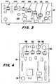
- Figures 3 and 4 show the two printed circuit boards 96, 100 from the inside of the housing. 3, are on the second circuit board 100 seven Hall sensors 102, 104, 106, 108, 110, 112, 114 arranged in an arc.
- Two mounting holes 116, 118 are used for mounting on the cover plate 20.
- FIG on the first printed circuit board 96 four Hall sensors 120, 122, 124, 126 arranged in an arc.
- Both circuit boards 96, 100 are equipped with other electrical components, which as Rectangles indicated in Figures 3 and 4, but not in more detail are designated. These are resistors, Voltage regulators, integrated modules and the like, that of the signal processing of the Hall sensors 102 to 114 and 120 serve up to 126.
- the support member 82 carries itself up substantially extending boom 88, at its upper end Permanent magnet 128 is attached.
- the support member 82 moves the permanent magnet 128 parallel to Surface of the first printed circuit board 96 along an arc, on which the Hall sensors 120, 122, 124, 126 of the first Printed circuit board 96 are arranged.
- the magnetic field of Permanent magnets 128 one after the other Hall sensors 120, 122, 124, 126 detected so that these according to the position of the selector lever 14 control signals to one Submit transmission control.
- the Hall sensor 120 responds to that Magnetic field of the permanent magnet 128 on reaching the Hallway R responds to Hall sensor 122 when it reaches Hall sensor 124 responds to first forward lane F1 and when the selector lever is in parking position P, the speaks Hall sensor 126 on.
- the pivot part 26 also carries one in its upper region Permanent magnets 130.
- the permanent magnet 130 moves parallel to the surface of the second printed circuit board 100 along an arc on which the Hall sensors 102, 104, 106, 108, 110, 112, 114 of the second Printed circuit board 100 are arranged.
- the magnetic field of the Permanent magnets 130 one after the other several of the Hall sensors 102, 104, 106, 108, 110, 112, 114 detected so that this according to the position of the selector lever 14th Send control signals to a transmission control.
- a microswitch can be located at point 132 of cover plate 20 be mounted, the trigger element in the swivel path of the Selector lever 14 is located and when the parking position P is reached appeals. Furthermore, a microswitch can be placed in place 134 of the base housing 18 are mounted, the trigger element also lies in the swivel path of the selector lever 14 and Reaching neutral position N responds. The signals of the Microswitches are not shown Transmission control supplied and evaluated there.
- the switching unit shown with the integrated Switching elements for preselecting the vehicle speed as well a degree of actuation for hand throttle is one Module for manual, stepless switching of a stepless Gearbox under load in agricultural tractors.
Landscapes
- Engineering & Computer Science (AREA)
- General Engineering & Computer Science (AREA)
- Mechanical Engineering (AREA)
- Arrangement Or Mounting Of Control Devices For Change-Speed Gearing (AREA)
- Control Of Transmission Device (AREA)
- Gear-Shifting Mechanisms (AREA)
Applications Claiming Priority (2)
| Application Number | Priority Date | Filing Date | Title |
|---|---|---|---|
| DE19924791 | 1999-05-29 | ||
| DE19924791A DE19924791C1 (de) | 1999-05-29 | 1999-05-29 | Schaltvorrichtung für Kraftfahrzeuggetriebe |
Publications (2)
| Publication Number | Publication Date |
|---|---|
| EP1058034A1 true EP1058034A1 (fr) | 2000-12-06 |
| EP1058034B1 EP1058034B1 (fr) | 2003-10-08 |
Family
ID=7909689
Family Applications (1)
| Application Number | Title | Priority Date | Filing Date |
|---|---|---|---|
| EP00111232A Revoked EP1058034B1 (fr) | 1999-05-29 | 2000-05-25 | Dispositif sélecteur pour boíte de vitesses de véhicule |
Country Status (8)
| Country | Link |
|---|---|
| US (1) | US6530293B1 (fr) |
| EP (1) | EP1058034B1 (fr) |
| AR (1) | AR024126A1 (fr) |
| AT (1) | ATE251726T1 (fr) |
| BR (1) | BR0002520A (fr) |
| CA (1) | CA2309067C (fr) |
| DE (2) | DE19924791C1 (fr) |
| TR (1) | TR200001507A2 (fr) |
Cited By (4)
| Publication number | Priority date | Publication date | Assignee | Title |
|---|---|---|---|---|
| EP1607659A3 (fr) * | 2004-06-17 | 2009-09-16 | Deere & Company | Levier de commande avec roue dans un espace semi-clos |
| CN103836172A (zh) * | 2012-11-27 | 2014-06-04 | 重庆长安汽车股份有限公司 | 汽车电子换档器及换档方法 |
| IT201600069273A1 (it) * | 2016-07-04 | 2018-01-04 | Silatech S R L | Dispositivo di comando cambio a struttura modulare. |
| DE102022108446A1 (de) | 2022-04-07 | 2023-10-12 | Autoliv Development Ab | Gurtaufroller mit einer Einrichtung zur Sensierung der Gurtbandauszugslänge |
Families Citing this family (45)
| Publication number | Priority date | Publication date | Assignee | Title |
|---|---|---|---|---|
| JP2002089676A (ja) * | 2000-09-13 | 2002-03-27 | Suzuki Motor Corp | 変速制御装置 |
| JP2002087100A (ja) * | 2000-09-13 | 2002-03-26 | Suzuki Motor Corp | シフトレバー装置 |
| US6564632B2 (en) * | 2001-01-11 | 2003-05-20 | Rochester Gauges, Inc. | Liquid level gauge with removable hall device |
| DE60214958T2 (de) * | 2001-11-22 | 2007-03-01 | Kabushiki Kaisha Tokai Rika Denki Seisakusho | Schaltvorrichtung |
| DE10231015B4 (de) * | 2002-07-09 | 2006-08-31 | ZF Lemförder Metallwaren AG | Bewegungsübersetzer für eine isodistante Schaltsensorik |
| JP2004138235A (ja) * | 2002-08-20 | 2004-05-13 | Tokai Rika Co Ltd | シフトレバー装置 |
| US6817262B2 (en) * | 2002-11-04 | 2004-11-16 | Grand Haven Stamped Products, Division Of Jsj Corporation | Interlock device with stamped lead frame |
| USPP15990P3 (en) * | 2003-04-23 | 2005-09-20 | J. C. Bakker & Sons Limited | Lilac plant named ‘Golden Eclipse’ |
| US7221248B2 (en) * | 2003-05-15 | 2007-05-22 | Grand Haven Stamped Products | Solenoid with noise reduction |
| US7393304B2 (en) | 2003-05-15 | 2008-07-01 | Grand Haven Stamped Products | Shifter with gear position indicator |
| US20060000304A1 (en) * | 2004-06-17 | 2006-01-05 | Deere & Company, A Delaware Corporation | Control lever with partially enclosed rotary wheel |
| US7293578B2 (en) | 2004-01-22 | 2007-11-13 | Rochester Gauges, Inc. | Gauge assembly having a stop fill device |
| US7921873B2 (en) | 2004-01-22 | 2011-04-12 | Rochester Gauges, Inc. | Service valve assembly having a stop-fill device and a liquid level indicating dial |
| US7726334B2 (en) | 2004-01-22 | 2010-06-01 | Rochester Gauges, Inc. | Service valve assembly having a stop-fill device and remote liquid level indicator |
| DE102004006150B3 (de) * | 2004-02-07 | 2005-09-15 | Teleflex Automotive Germany Gmbh | Steuereinrichtung zur elektronischen Schrittschaltsteuerung für Automatikgetriebe |
| JP2005271789A (ja) * | 2004-03-25 | 2005-10-06 | Atsumi Tec:Kk | 車両用自動変速操作装置 |
| JP2005273818A (ja) * | 2004-03-25 | 2005-10-06 | Atsumi Tec:Kk | 車両用自動変速操作装置 |
| JP2005306276A (ja) * | 2004-04-23 | 2005-11-04 | Tokai Rika Co Ltd | 二方向回動検出装置及びシフトレバー装置 |
| US7568404B2 (en) | 2004-07-26 | 2009-08-04 | Ghsp, A Division Of Jsj Corporation | Shifter having neutral lock |
| US7328782B2 (en) * | 2004-07-26 | 2008-02-12 | Grand Haven Stamped Products Company, A Division Of Jsj Corporation | Vehicle shifter with powered pawl having neutral lock |
| DE102004060771B4 (de) * | 2004-12-17 | 2006-12-21 | Audi Ag | Vorrichtung zum Schalten von Übersetzungsänderungen |
| JP3968104B2 (ja) * | 2005-03-18 | 2007-08-29 | ジヤトコ株式会社 | 自動変速機におけるマニュアルプレートの回動範囲規制構造 |
| DE102006044404B4 (de) * | 2005-09-16 | 2009-03-05 | Preh Gmbh | Vorrichtung und Verfahren zur Erkennung einer Winkelstellung eines Wählhebels |
| USD583693S1 (en) | 2006-03-30 | 2008-12-30 | Rochester Gauges, Inc. | Dial assembly for a gauge |
| US7563199B2 (en) * | 2006-06-28 | 2009-07-21 | Equipment Technology, Inc. | Apparatus and method for controlling rotational speed and direction of a crop sprayer |
| KR100783516B1 (ko) | 2006-08-17 | 2007-12-11 | 현대자동차주식회사 | 변속 레버 시스템 |
| KR100800126B1 (ko) * | 2006-08-17 | 2008-01-31 | 에스엘 주식회사 | 전자식 변속 레버 |
| WO2008022340A2 (fr) * | 2006-08-18 | 2008-02-21 | Rochester Gauges, Inc. | Ensemble de robinet de service doté d'un dispositif d'arrêt de remplissage et d'un indicateur du niveau de liquide |
| US7701203B2 (en) * | 2007-05-11 | 2010-04-20 | Caterpillar Inc. | Method of sensing a position of a movable component of an operator interface in a machine |
| US7761254B2 (en) * | 2007-05-11 | 2010-07-20 | Caterpillar Inc | Operator interface assembly including a Hall effect element and machine using same |
| JP4986742B2 (ja) * | 2007-06-28 | 2012-07-25 | 株式会社アツミテック | 車両用変速操作装置 |
| US7690323B2 (en) * | 2007-10-31 | 2010-04-06 | Rochester Gauges, Inc. | Gauge head assembly with non-magnetic insert |
| US8656802B2 (en) | 2011-09-30 | 2014-02-25 | Kongsberg Automotive Ab | Shifter assembly for providing mechanical and electronic actuation to a transmission of a vehicle and a method of operating the shifter assembly |
| JP6006027B2 (ja) * | 2012-07-18 | 2016-10-12 | 株式会社東海理化電機製作所 | ポジションセンサ |
| DE102012213177B4 (de) * | 2012-07-26 | 2019-12-19 | Schaeffler Technologies AG & Co. KG | Schaltdom für ein Schaltgetriebe eines Kraftfahrzeugs |
| EP3120048B1 (fr) * | 2014-03-18 | 2018-06-20 | Kongsberg Automotive AB | Système de changement de vitesse comprenant un ensemble capteur de position |
| WO2015173834A2 (fr) * | 2014-05-15 | 2015-11-19 | Pricol Limited | Levier de changement de vitesse électro-mécanique doté d'un éclairage pour des véhicules électriques |
| DE102014116990B4 (de) | 2014-11-20 | 2023-03-02 | Hyundai Motor Company | Kraftfahrzeuggetriebe mit Schalthebel und Getriebesensormodul |
| US9593770B2 (en) * | 2015-04-15 | 2017-03-14 | Fca Us Llc | Automatic transmission shifter with speed sensitive damping |
| EP3344899B1 (fr) | 2015-09-03 | 2019-05-22 | Kongsberg Automotive AB | Ensemble de changement de vitesse comprenant un ensemble de capteurs de position |
| US9879775B2 (en) * | 2015-11-13 | 2018-01-30 | Sl Corporation | Shifting lever assembly |
| US10012307B2 (en) * | 2016-02-25 | 2018-07-03 | Fca Us Llc | Automatic transmission shifter with speed sensitive damping |
| US10281028B2 (en) * | 2016-05-26 | 2019-05-07 | Dura Operating, Llc | Shifter location system for a motor vehicle |
| JP6391632B2 (ja) * | 2016-07-28 | 2018-09-19 | 株式会社東海理化電機製作所 | シフト装置 |
| US10871220B2 (en) * | 2017-04-11 | 2020-12-22 | Lokar, Inc. | Shifter mechanism with manual shift function |
Citations (6)
| Publication number | Priority date | Publication date | Assignee | Title |
|---|---|---|---|---|
| US4022078A (en) * | 1976-04-05 | 1977-05-10 | Clark Equipment Company | Shift control mechanism |
| US4116086A (en) * | 1976-11-26 | 1978-09-26 | Incom International, Inc. | Changeable gate plate means for lever control devices |
| US5277077A (en) * | 1992-09-28 | 1994-01-11 | Grand Haven Stamped Products, Div. Of Jsj Corporation | Modular vehicle shifter and method of manufacture |
| EP0620385A1 (fr) * | 1993-04-13 | 1994-10-19 | Jaeger | Ensemble de commande pour boîte de vitesses mécanique et système de commande incorporant celui-ci |
| EP0754885A2 (fr) * | 1993-12-01 | 1997-01-22 | Deere & Company | Agencement de levier de commande |
| WO1999011951A1 (fr) * | 1997-08-19 | 1999-03-11 | Kongsberg Automotive Ab | Dispositif de manoeuvre |
Family Cites Families (7)
| Publication number | Priority date | Publication date | Assignee | Title |
|---|---|---|---|---|
| DE3138827A1 (de) * | 1981-09-30 | 1983-04-14 | Wabco Westinghouse Fahrzeugbremsen GmbH, 3000 Hannover | Gangwaehler fuer ein getriebe |
| US4912997A (en) * | 1989-06-02 | 1990-04-03 | Chrysler Corporation | Electric shift selector mechanism for transmission |
| DE69212446T2 (de) * | 1991-12-19 | 1996-11-28 | Mitsubishi Heavy Ind Ltd | Elektronisch, gesteuertes, automatisches Getriebe eines Fahrzeugs |
| US5243871A (en) * | 1992-08-13 | 1993-09-14 | Ford New Holland, Inc. | Control lever apparatus for generating electrical control signals |
| JP2916889B2 (ja) * | 1996-01-11 | 1999-07-05 | ナイルス部品株式会社 | 車両の変速操作装置 |
| DE19650154C2 (de) * | 1996-12-04 | 1999-06-10 | Lemfoerder Metallwaren Ag | Schaltvorrichtung für ein Getriebe eines KFZ mit einer mit Sensoren, Leuchtdioden, Prozessen und anderen elektronischen Bauelementen bestückten Leiterplatte und Verfahren zur Herstellung einer gekrümmten Leiterplatte zur Verwendung in einer solchen Schaltvorrichtung |
| US5809835A (en) * | 1997-01-21 | 1998-09-22 | Ford Global Technologies, Inc. | Manual transmission shift lever |
-
1999
- 1999-05-29 DE DE19924791A patent/DE19924791C1/de not_active Expired - Lifetime
-
2000
- 2000-05-16 US US09/571,245 patent/US6530293B1/en not_active Expired - Lifetime
- 2000-05-19 CA CA002309067A patent/CA2309067C/fr not_active Expired - Fee Related
- 2000-05-25 TR TR2000/01507A patent/TR200001507A2/xx unknown
- 2000-05-25 EP EP00111232A patent/EP1058034B1/fr not_active Revoked
- 2000-05-25 AT AT00111232T patent/ATE251726T1/de active
- 2000-05-25 DE DE50003974T patent/DE50003974D1/de not_active Revoked
- 2000-05-26 AR ARP000102604A patent/AR024126A1/es active IP Right Grant
- 2000-05-29 BR BR0002520-8A patent/BR0002520A/pt not_active IP Right Cessation
Patent Citations (6)
| Publication number | Priority date | Publication date | Assignee | Title |
|---|---|---|---|---|
| US4022078A (en) * | 1976-04-05 | 1977-05-10 | Clark Equipment Company | Shift control mechanism |
| US4116086A (en) * | 1976-11-26 | 1978-09-26 | Incom International, Inc. | Changeable gate plate means for lever control devices |
| US5277077A (en) * | 1992-09-28 | 1994-01-11 | Grand Haven Stamped Products, Div. Of Jsj Corporation | Modular vehicle shifter and method of manufacture |
| EP0620385A1 (fr) * | 1993-04-13 | 1994-10-19 | Jaeger | Ensemble de commande pour boîte de vitesses mécanique et système de commande incorporant celui-ci |
| EP0754885A2 (fr) * | 1993-12-01 | 1997-01-22 | Deere & Company | Agencement de levier de commande |
| WO1999011951A1 (fr) * | 1997-08-19 | 1999-03-11 | Kongsberg Automotive Ab | Dispositif de manoeuvre |
Cited By (4)
| Publication number | Priority date | Publication date | Assignee | Title |
|---|---|---|---|---|
| EP1607659A3 (fr) * | 2004-06-17 | 2009-09-16 | Deere & Company | Levier de commande avec roue dans un espace semi-clos |
| CN103836172A (zh) * | 2012-11-27 | 2014-06-04 | 重庆长安汽车股份有限公司 | 汽车电子换档器及换档方法 |
| IT201600069273A1 (it) * | 2016-07-04 | 2018-01-04 | Silatech S R L | Dispositivo di comando cambio a struttura modulare. |
| DE102022108446A1 (de) | 2022-04-07 | 2023-10-12 | Autoliv Development Ab | Gurtaufroller mit einer Einrichtung zur Sensierung der Gurtbandauszugslänge |
Also Published As
| Publication number | Publication date |
|---|---|
| BR0002520A (pt) | 2001-01-02 |
| CA2309067A1 (fr) | 2000-11-29 |
| TR200001507A2 (tr) | 2000-12-21 |
| US6530293B1 (en) | 2003-03-11 |
| DE19924791C1 (de) | 2001-02-08 |
| DE50003974D1 (de) | 2003-11-13 |
| AR024126A1 (es) | 2002-09-04 |
| ATE251726T1 (de) | 2003-10-15 |
| CA2309067C (fr) | 2004-11-09 |
| EP1058034B1 (fr) | 2003-10-08 |
Similar Documents
| Publication | Publication Date | Title |
|---|---|---|
| EP1058034B1 (fr) | Dispositif sélecteur pour boíte de vitesses de véhicule | |
| EP0656492B1 (fr) | Disposition de levier de commande d'une boite de vitesses | |
| DE69814095T2 (de) | Manövervorrichtung | |
| EP2457002B1 (fr) | Dispositif de detection de la position d'un levier de changement et/ou de selection de vitesses pour une boite de vitesses et dispositif de commande pour la boite de vitesses d'un vehicule automobile | |
| DE3824296C2 (fr) | ||
| EP0175061A1 (fr) | Transmetteur pour la boîte de vitesse d'un véhicule automobile | |
| DE69023148T2 (de) | Getriebegangfühler. | |
| DE69622165T2 (de) | Schalteinrichtung mit mittel zum betätigen des zündschossmechanismus durch ein kabel | |
| WO1988009451A1 (fr) | Console de changement de vitesses | |
| EP0699853B1 (fr) | Tringlerie de sélection des vitesses pour boîte de vitesse d'un véhicule | |
| DE60116373T2 (de) | Gangschaltmechanismus für ein kraftfahrzeug | |
| EP1611376A2 (fr) | Changement de vitesses du type shift-by-wire avec position p | |
| EP1181469B1 (fr) | Dispositif de changement de vitesses pour une boite automatique d'un vehicule automobile | |
| EP1082557A1 (fr) | Dispositif de transmission pour vehicules | |
| DE102016122344B4 (de) | Betätigungseinrichtung und deren Verwendung für ein elektromechanisches oder hydromechanisches Kraftfahrzeuggetriebe insbesondere eines landwirtschaftlichen Nutzfahrzeugs | |
| EP1531290A2 (fr) | Dispositif de sélection de vitesse | |
| EP1488140A1 (fr) | Dispositif de selection pour commander la selection de rapports d'une boite de vitesses d'automobile | |
| DE10257631A1 (de) | Verstellbares Fußhebelwerk | |
| EP0230661A1 (fr) | Dispositif de changement de vitesse | |
| DE10218233A1 (de) | Betriebsart-Steuergerät für ein Automatikgetriebe | |
| DE4101010A1 (de) | Vorrichtung zur uebertragung einer steuer- oder schaltbewegung, insbesondere zum schalten eines kraftfahrzeuggetriebes | |
| EP0803664B1 (fr) | Dispositif de commande de vitesse manuelle pour commander une boíte de vitesses à plusieurs rapports | |
| EP0913604A1 (fr) | Arrêt avec ressort à lame pour boíte de vitesses | |
| DE19900412A1 (de) | Wählvorrichtung für ein Automatikgetriebe eines Kraftfahrzeuges | |
| DE69001529T2 (de) | Kontrollvorrichtung. |
Legal Events
| Date | Code | Title | Description |
|---|---|---|---|
| PUAI | Public reference made under article 153(3) epc to a published international application that has entered the european phase |
Free format text: ORIGINAL CODE: 0009012 |
|
| AK | Designated contracting states |
Kind code of ref document: A1 Designated state(s): AT BE CH CY DE DK ES FI FR GB GR IE IT LI LU MC NL PT SE |
|
| AX | Request for extension of the european patent |
Free format text: AL;LT;LV;MK;RO;SI |
|
| 17P | Request for examination filed |
Effective date: 20010606 |
|
| AKX | Designation fees paid |
Free format text: AT BE CH CY DE DK ES FI FR GB GR IE IT LI LU MC NL PT SE |
|
| 17Q | First examination report despatched |
Effective date: 20021129 |
|
| GRAH | Despatch of communication of intention to grant a patent |
Free format text: ORIGINAL CODE: EPIDOS IGRA |
|
| GRAA | (expected) grant |
Free format text: ORIGINAL CODE: 0009210 |
|
| GRAS | Grant fee paid |
Free format text: ORIGINAL CODE: EPIDOSNIGR3 |
|
| AK | Designated contracting states |
Kind code of ref document: B1 Designated state(s): AT BE CH CY DE DK ES FI FR GB GR IE IT LI LU MC NL PT SE |
|
| PG25 | Lapsed in a contracting state [announced via postgrant information from national office to epo] |
Ref country code: IE Free format text: LAPSE BECAUSE OF FAILURE TO SUBMIT A TRANSLATION OF THE DESCRIPTION OR TO PAY THE FEE WITHIN THE PRESCRIBED TIME-LIMIT Effective date: 20031008 Ref country code: CY Free format text: LAPSE BECAUSE OF FAILURE TO SUBMIT A TRANSLATION OF THE DESCRIPTION OR TO PAY THE FEE WITHIN THE PRESCRIBED TIME-LIMIT Effective date: 20031008 Ref country code: NL Free format text: LAPSE BECAUSE OF FAILURE TO SUBMIT A TRANSLATION OF THE DESCRIPTION OR TO PAY THE FEE WITHIN THE PRESCRIBED TIME-LIMIT Effective date: 20031008 |
|
| REG | Reference to a national code |
Ref country code: GB Ref legal event code: FG4D Free format text: NOT ENGLISH |
|
| REG | Reference to a national code |
Ref country code: CH Ref legal event code: EP |
|
| REG | Reference to a national code |
Ref country code: IE Ref legal event code: FG4D Free format text: GERMAN |
|
| REF | Corresponds to: |
Ref document number: 50003974 Country of ref document: DE Date of ref document: 20031113 Kind code of ref document: P |
|
| GBT | Gb: translation of ep patent filed (gb section 77(6)(a)/1977) |
Effective date: 20031117 |
|
| PG25 | Lapsed in a contracting state [announced via postgrant information from national office to epo] |
Ref country code: DK Free format text: LAPSE BECAUSE OF FAILURE TO SUBMIT A TRANSLATION OF THE DESCRIPTION OR TO PAY THE FEE WITHIN THE PRESCRIBED TIME-LIMIT Effective date: 20040108 Ref country code: SE Free format text: LAPSE BECAUSE OF FAILURE TO SUBMIT A TRANSLATION OF THE DESCRIPTION OR TO PAY THE FEE WITHIN THE PRESCRIBED TIME-LIMIT Effective date: 20040108 Ref country code: GR Free format text: LAPSE BECAUSE OF FAILURE TO SUBMIT A TRANSLATION OF THE DESCRIPTION OR TO PAY THE FEE WITHIN THE PRESCRIBED TIME-LIMIT Effective date: 20040108 |
|
| PG25 | Lapsed in a contracting state [announced via postgrant information from national office to epo] |
Ref country code: ES Free format text: LAPSE BECAUSE OF FAILURE TO SUBMIT A TRANSLATION OF THE DESCRIPTION OR TO PAY THE FEE WITHIN THE PRESCRIBED TIME-LIMIT Effective date: 20040119 |
|
| NLV1 | Nl: lapsed or annulled due to failure to fulfill the requirements of art. 29p and 29m of the patents act | ||
| PG25 | Lapsed in a contracting state [announced via postgrant information from national office to epo] |
Ref country code: LU Free format text: LAPSE BECAUSE OF NON-PAYMENT OF DUE FEES Effective date: 20040525 |
|
| PG25 | Lapsed in a contracting state [announced via postgrant information from national office to epo] |
Ref country code: BE Free format text: LAPSE BECAUSE OF NON-PAYMENT OF DUE FEES Effective date: 20040531 Ref country code: MC Free format text: LAPSE BECAUSE OF NON-PAYMENT OF DUE FEES Effective date: 20040531 Ref country code: CH Free format text: LAPSE BECAUSE OF NON-PAYMENT OF DUE FEES Effective date: 20040531 Ref country code: LI Free format text: LAPSE BECAUSE OF NON-PAYMENT OF DUE FEES Effective date: 20040531 |
|
| REG | Reference to a national code |
Ref country code: IE Ref legal event code: FD4D |
|
| ET | Fr: translation filed | ||
| PLBI | Opposition filed |
Free format text: ORIGINAL CODE: 0009260 |
|
| PLAX | Notice of opposition and request to file observation + time limit sent |
Free format text: ORIGINAL CODE: EPIDOSNOBS2 |
|
| 26 | Opposition filed |
Opponent name: ZF LEMFOERDER METALLWAREN AG Effective date: 20040708 |
|
| BERE | Be: lapsed |
Owner name: *DEERE & CY Effective date: 20040531 |
|
| PLBB | Reply of patent proprietor to notice(s) of opposition received |
Free format text: ORIGINAL CODE: EPIDOSNOBS3 |
|
| REG | Reference to a national code |
Ref country code: CH Ref legal event code: PL |
|
| RDAF | Communication despatched that patent is revoked |
Free format text: ORIGINAL CODE: EPIDOSNREV1 |
|
| APBP | Date of receipt of notice of appeal recorded |
Free format text: ORIGINAL CODE: EPIDOSNNOA2O |
|
| APAH | Appeal reference modified |
Free format text: ORIGINAL CODE: EPIDOSCREFNO |
|
| APBQ | Date of receipt of statement of grounds of appeal recorded |
Free format text: ORIGINAL CODE: EPIDOSNNOA3O |
|
| PG25 | Lapsed in a contracting state [announced via postgrant information from national office to epo] |
Ref country code: PT Free format text: LAPSE BECAUSE OF NON-PAYMENT OF DUE FEES Effective date: 20040308 |
|
| PGFP | Annual fee paid to national office [announced via postgrant information from national office to epo] |
Ref country code: DE Payment date: 20080421 Year of fee payment: 9 |
|
| PGFP | Annual fee paid to national office [announced via postgrant information from national office to epo] |
Ref country code: AT Payment date: 20080502 Year of fee payment: 9 |
|
| PGFP | Annual fee paid to national office [announced via postgrant information from national office to epo] |
Ref country code: FI Payment date: 20080530 Year of fee payment: 9 Ref country code: IT Payment date: 20080527 Year of fee payment: 9 |
|
| APBU | Appeal procedure closed |
Free format text: ORIGINAL CODE: EPIDOSNNOA9O |
|
| RDAG | Patent revoked |
Free format text: ORIGINAL CODE: 0009271 |
|
| STAA | Information on the status of an ep patent application or granted ep patent |
Free format text: STATUS: PATENT REVOKED |
|
| PGFP | Annual fee paid to national office [announced via postgrant information from national office to epo] |
Ref country code: GB Payment date: 20080529 Year of fee payment: 9 |
|
| 27W | Patent revoked |
Effective date: 20081014 |
|
| GBPR | Gb: patent revoked under art. 102 of the ep convention designating the uk as contracting state |
Effective date: 20081014 |
|
| PGFP | Annual fee paid to national office [announced via postgrant information from national office to epo] |
Ref country code: FR Payment date: 20080519 Year of fee payment: 9 |