EP1058063B1 - Flüssigbrennstoffeinspritzdüse für Gasturbinenbrenner - Google Patents
Flüssigbrennstoffeinspritzdüse für Gasturbinenbrenner Download PDFInfo
- Publication number
- EP1058063B1 EP1058063B1 EP00304601A EP00304601A EP1058063B1 EP 1058063 B1 EP1058063 B1 EP 1058063B1 EP 00304601 A EP00304601 A EP 00304601A EP 00304601 A EP00304601 A EP 00304601A EP 1058063 B1 EP1058063 B1 EP 1058063B1
- Authority
- EP
- European Patent Office
- Prior art keywords
- liquid fuel
- holes
- compressed air
- injector
- gas turbine
- Prior art date
- Legal status (The legal status is an assumption and is not a legal conclusion. Google has not performed a legal analysis and makes no representation as to the accuracy of the status listed.)
- Expired - Lifetime
Links
- 239000000446 fuel Substances 0.000 title claims description 58
- 239000007788 liquid Substances 0.000 title claims description 48
- 238000011144 upstream manufacturing Methods 0.000 claims description 3
- 238000002485 combustion reaction Methods 0.000 description 7
- 230000000694 effects Effects 0.000 description 2
- 238000000889 atomisation Methods 0.000 description 1
- 239000006227 byproduct Substances 0.000 description 1
- 239000003344 environmental pollutant Substances 0.000 description 1
- 239000012530 fluid Substances 0.000 description 1
- 239000012212 insulator Substances 0.000 description 1
- 238000002955 isolation Methods 0.000 description 1
- 239000000203 mixture Substances 0.000 description 1
- 231100000719 pollutant Toxicity 0.000 description 1
- 238000000926 separation method Methods 0.000 description 1
Images
Classifications
-
- F—MECHANICAL ENGINEERING; LIGHTING; HEATING; WEAPONS; BLASTING
- F23—COMBUSTION APPARATUS; COMBUSTION PROCESSES
- F23R—GENERATING COMBUSTION PRODUCTS OF HIGH PRESSURE OR HIGH VELOCITY, e.g. GAS-TURBINE COMBUSTION CHAMBERS
- F23R3/00—Continuous combustion chambers using liquid or gaseous fuel
- F23R3/02—Continuous combustion chambers using liquid or gaseous fuel characterised by the air-flow or gas-flow configuration
- F23R3/04—Air inlet arrangements
- F23R3/10—Air inlet arrangements for primary air
- F23R3/12—Air inlet arrangements for primary air inducing a vortex
-
- F—MECHANICAL ENGINEERING; LIGHTING; HEATING; WEAPONS; BLASTING
- F23—COMBUSTION APPARATUS; COMBUSTION PROCESSES
- F23D—BURNERS
- F23D11/00—Burners using a direct spraying action of liquid droplets or vaporised liquid into the combustion space
- F23D11/10—Burners using a direct spraying action of liquid droplets or vaporised liquid into the combustion space the spraying being induced by a gaseous medium, e.g. water vapour
- F23D11/101—Burners using a direct spraying action of liquid droplets or vaporised liquid into the combustion space the spraying being induced by a gaseous medium, e.g. water vapour medium and fuel meeting before the burner outlet
-
- F—MECHANICAL ENGINEERING; LIGHTING; HEATING; WEAPONS; BLASTING
- F23—COMBUSTION APPARATUS; COMBUSTION PROCESSES
- F23R—GENERATING COMBUSTION PRODUCTS OF HIGH PRESSURE OR HIGH VELOCITY, e.g. GAS-TURBINE COMBUSTION CHAMBERS
- F23R3/00—Continuous combustion chambers using liquid or gaseous fuel
- F23R3/28—Continuous combustion chambers using liquid or gaseous fuel characterised by the fuel supply
- F23R3/286—Continuous combustion chambers using liquid or gaseous fuel characterised by the fuel supply having fuel-air premixing devices
Definitions
- the present invention relates to a liquid fuel injector for burners in gas turbines.
- gas turbines are machines which consist of a compressor and of a turbine with one or more stages, wherein these components are connected to one another by a rotary shaft, and wherein a combustion chamber is provided between the compressor and the turbine.
- the compressor In order to pressurise the compressor, it is supplied with air obtained from the external environment.
- the compressed air passes through a series of pre-mixing chambers, which end in a nozzle or a converging portion, into each of which an injector supplies fuel which is mixed with the air, in order to form an air-fuel mixture to be burnt.
- the high-temperature, high-pressure gas reaches the turbine, which transforms the enthalpy of the gas into mechanical energy which is available to a user.
- burner units Between -the compressor and the combustion chamber there is provided a series of burner units, the functions of which include supplying the liquid fuel, obtained from a remote tank, to the combustion chamber.
- One such unit is shown in US-A-5 778 676 .
- Known burner units have a complex structure, inside which there is present an injector, contained in a converging body, which in the technical language is generally known as the shroud.
- the injector which, it will be appreciated, is connected to a supply duct for the liquid fuel, generally has a body which is provided with a cylindrical portion and a pointed end portion.
- the liquid fuel injectors for burners in known gas turbines have a duct which is used in order to permit passage of the fuel, and are provided with ducts for the inflow of compressed air from the compressor of the turbine.
- Both the duct for the fuel and the ducts for the compressed air end in corresponding outlet holes, wherein the air output from the injector is used to vaporise the fuel in order to improve the characteristics of the combustion.
- the converging body there is associated with the converging body an element which is generally known according to the art as the swirler, which is used to intercept the flow of air obtained from the compressor, and has a complex shape, consisting of two series of blades, oriented in opposite directions, which are designed to produce a turbulent flow of the compressed air obtained from the compressor, thus permitting corresponding mixing of the air itself with the liquid fuel injected by the injector into the pre-mixing chamber.
- the swirler which is used to intercept the flow of air obtained from the compressor, and has a complex shape, consisting of two series of blades, oriented in opposite directions, which are designed to produce a turbulent flow of the compressed air obtained from the compressor, thus permitting corresponding mixing of the air itself with the liquid fuel injected by the injector into the pre-mixing chamber.
- the present invention thus seeks to provide a liquid fuel injector for burners in gas turbines, which has an extremely simple and compact structure, whilst maintaining optimum fluid-dynamic characteristics, as previously described.
- the invention also seeks to provide a liquid fuel injector for burners in gas turbines, which permits optimum reliability of use of the machine.
- the invention further seeks to provide a liquid fuel injector for burners in gas turbines, which can be produced at a low cost, and consists of a reduced number of component parts.
- a gas turbine burner comprising a premixing chamber including a cylindrical section and a downstream converging portion and an element upstream of said converging portion to create turbulence in the flow of compressed air obtained from the compressor of the said gas turbine, and an injector comprising a body which ends in a tip and is provided with at least one duct for passage of the liquid fuel, and ducts for the inflow of compressed air from the said compressor, wherein the said duct for the liquid fuel and the ducts for the compressed air end in respective outlet holes in which the tip of the said injector ends at the median part of the converging portion of the said pre-mixing chamber.
- the holes for lateral discharge of the compressed air are located downstream from the holes from which the liquid fuel is discharged.
- each of the holes for lateral discharge of the compressed air is located on a line parallel to the axis of the injector, relative to the corresponding hole for discharge of the liquid fuel.
- the holes for lateral discharge of the compressed air, and the holes for discharge of the liquid fuel are located downstream from the element for the turbulence, and in a position which is clearly separated from the latter.
- the body of the injector has a plurality of intake ducts, in order to permit intake of the compressed air from the said compressor.
- the injector inside its own tip the injector has a duct which is in communication with the ducts for passage of the compressed air, and ends in a hole, from the front of which the compressed air is discharged.
- the injector according to the present invention is provided with a tube, which is outside the one for supply of the liquid fuel, and acts as a thermal insulator.
- the two tubes are kept equally spaced from one another by means of a corresponding spring.
- liquid fuel injector for burners in gas turbines is indicated as a whole by the reference number 10.
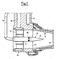
- the liquid fuel injector 10 for burners in gas turbines is of the type used inside burners which are provided with a pre-mixing chamber 62 and an element 13, generally known as a swirler, which is used in order to create appropriate turbulence in the flow of compressed air obtained from the compressor of the gas turbine.
- the pre-mixing chamber 62 has a first section 60, which is substantially cylindrical, and a final converging portion 61, which according to the art is known as the shroud.
- Figure 1 also shows the line 63 of separation between the cylindrical section 60 and the final converging portion 61.
- the injector 10 is connected to a tube 14, through which the liquid fuel is supplied, whereas there are also associated with the pre-mixing chamber 62 a primary gas duct 70 and a duct 71, which belong to the pilot circuit of the flame.
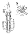
- the injector 10 comprises a body 11, which ends in a tip 12, and is provided with a duct 25 for passage of the fuel obtained from the tube 21.
- the duct 25 for the liquid fuel is extended inside a structure 26, which is described in greater detail hereinafter, and communicates with outlet holes 22 and 23 for the fuel.
- the injector 10 is inserted centrally relative to the swirler 13, for a section which corresponds to part of the length of the body 11.
- the tip 12 of the injector 10 ends at the median part of the converging portion 61 of the pre-mixing chamber 62, leaving a substantial space free before the outlet 64 of the converging portion 61.
- the injector is also provided with ducts indicated by the reference numbers 48 and 58, which permit inflow of compressed air obtained from the compressor (not shown) of the gas turbine.
- the ducts 48 and 58 communicate with outlet holes 20 and 21 for the compressed air.
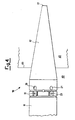
- the holes 20 and 21 for lateral discharge of the compressed air are located downstream from the holes 22 and 23, from which the liquid fuel is discharged.
- each of these holes 20 and 21 for lateral discharge of the compressed air is located on a line which is parallel to the axis of the said injector 10, relative to the corresponding holes 22 and 23 for discharge of the liquid fuel.
- An important characteristic of the injector according to the invention consists in the fact that the holes 20 and 21 for lateral discharge of the compressed air, and the holes 22 and 23 for discharge of the liquid fuel, are located downstream from the swirler 13, and in a position which is clearly separated from the latter.
- Figure 4 also shows in detail the fact that the holes 20, 21 for lateral discharge of the compressed air, and the holes 22 and 23 for discharge of the liquid fuel, are located inside the cylindrical section 60 of the pre-mixing chamber 62 of the burner.
- both the holes 20 and 21 for lateral discharge of the compressed air, and the holes 22 and 23 for discharge of the liquid fuel, have their own axis oriented radially relative to the body 11 of the injector 10.
- both the holes 20 and 21 for lateral discharge of the compressed air, and the holes 22 and 23 for discharge of the liquid fuel have an oval cross-section.
- the holes 22 and 23 are preferably smaller than the holes 20 and 21.
- the body 11 of the injector 10 has a central hole, inside which the tube 14 for supply of the liquid fuel is inserted.
- the body 11 of the injector 10 also has a plurality of intake ducts 18, 28, 38 in order to permit intake of the compressed air from the compressor.
- the injector 10 also has a channel 19, which communicates with the channels 48 and 58, and ends in a hole 17, from the front of which the compressed air is discharged.
- an air gap 40 is also present.
- the tube 14 for supply of the liquid fuel has an isolation gap 16, which is provided such as to surround, together with a spring 15, an inner pipe 20 which defines the duct 25 for the liquid fuel.
- the aforementioned drilled structure 26 the function of which is to connect the end portion of the tube 14 for supply of the liquid fuel, such as to create a single channel 25 for passage of the liquid fuel.
- the drilled structure 26 communicates with the holes 22 and 23, from which the liquid fuel is discharged.
- the liquid fuel is supplied from a remote tank, by means of the tube 14, to the injector 10, such as to supply to the main flame of the burner.
- the compressed air obtained from the burner is admitted upstream from the injector 10, and comes into contact with the swirler 13, such that turbulence is created in the flow of compressed air, and this makes it possible to stabilise the flame downstream from the injector 10.
- the liquid fuel travels along the duct 25, and is discharged from the holes 22 and 23, which are disposed radially along the body 11 of the injector 10.
- the air obtained from the compressor travels along the ducts 48 and 58, and is discharged from the outlet holes 20 and 21.
- the compressed air also follows the duct 19, which in turn communicates with the ducts 48 and 58, such as to be discharged at the front from the hole 17.
- tip 12 of the injector 10 ends at the median part of the converging portion 61 of the pre-mixing chamber 62.
- This characteristic in association with the converging shape of the portion 61, permits optimum properties of the flame.
Landscapes
- Engineering & Computer Science (AREA)
- Chemical & Material Sciences (AREA)
- Combustion & Propulsion (AREA)
- Mechanical Engineering (AREA)
- General Engineering & Computer Science (AREA)
- Fuel-Injection Apparatus (AREA)
- Nozzles (AREA)
- Gas Burners (AREA)
Claims (10)
- Gasturbinenbrenner, aufweisend: eine Vormischkammer (62) mit einem zylindrischen Abschnitt (60) und einem stromabwärts zusammenlaufenden Abschnitt (61) und einem Element (13) stromaufwärts von dem zusammenlaufenden Abschnitt (61), um eine Turbulenz in dem Strom der aus dem Kompressor der Gasturbine erhaltenen Druckluft zu erzeugen, und eine Einspritzdüse (10) mit einem Körper (11), welcher in einer Spitze (12) endet und mit wenigstens einem Kanal (25) für den Durchtritt von Flüssigbrennstoff, und Kanälen (48, 58) für den Einstrom von Druckluft aus dem Kompressor versehen ist, wobei der Kanal (25) für den Flüssigbrennstoff und die Kanäle für die Druckluft in entsprechenden Auslasslöchern (20, 21, 22, 23) enden, dadurch gekennzeichnet, dass die Spitze (12) der Einspritzdüse (10) an dem mittigen Teil des zusammenlaufenden Abschnitts (61) der Vormischkammer (62) endet.
- Gasturbinenbrenner nach Anspruch 1, dadurch gekennzeichnet, dass die Löcher (20, 21) für die seitliche Ausgabe der Druckluft stromabwärts von den Löchern (22, 23), aus welchen der Flüssigbrennstoff ausgegeben wird, angeordnet sind.
- Gasturbinenbrenner nach Anspruch 2, dadurch gekennzeichnet, dass jedes von den Löchern (20, 21) für die seitliche Ausgabe der Druckluft zu dem entsprechenden Loch (22, 23) für die Ausgabe des Flüssigbrennstoffs ausgerichtet ist.
- Gasturbinenbrenner nach Anspruch 3, dadurch gekennzeichnet, dass die Löcher (20, 21) für die seitliche Ausgabe der Druckluft und die Löcher (22, 23) für die Ausgabe des Flüssigbrennstoffs stromabwärts von dem Element (13) für die Turbulenz und in einer Position angeordnet sind, welche deutlich von der letzteren getrennt ist.
- Gasturbinenbrenner nach Anspruch 4, dadurch gekennzeichnet, dass die Löcher (20, 21) für die seitliche Ausgabe der Druckluft und die Löcher (22, 23) für die Ausgabe des Flüssigbrennstoffs in dem zylindrischen Abschnitt (60) der Vormischkammer (62) angeordnet sind.
- Gasturbinenbrenner nach Anspruch 4 oder Anspruch 5, dadurch gekennzeichnet, dass sowohl die Löcher (20, 21) für die seitliche Ausgabe der Druckluft als auch die Löcher (22, 23) für die Ausgabe des Flüssigbrennstoffs ihre eigene in Bezug auf den Körper (11) der Einspritzdüse (10) ausgerichtete Achse haben.
- Gasturbinenbrenner nach Anspruch 1, dadurch gekennzeichnet, dass der Körper (11) der Einspritzdüse (10) ein mittiges Loch hat, in welches ein Rohr (14) für die Zuführung des Flüssigbrennstoffs eingesetzt ist.
- Gasturbinenbrenner nach Anspruch 7, dadurch gekennzeichnet, dass der Körper (11) der Einspritzdüse (10) mehrere Einlasskanäle (18, 28, 38) hat, um einen Einlass der Druckluft aus dem Kompressor zu ermöglichen.
- Gasturbinenbrenner nach Anspruch 8, dadurch gekennzeichnet, dass er in der Spitze (12) einen Kanal (19) hat, wobei der Kanal (19) mit den Kanälen (48, 58) in Verbindung steht, und in einem Loch (17) endet, von dessen Vorderseite die Druckluft ausgeben wird.
- Gasturbinenbrenner nach Anspruch 9, dadurch gekennzeichnet, dass er einen Luftspalt (40) in der Spitze (12) und in Verbindung mit dem Kanal (19) aufweist.
Applications Claiming Priority (2)
| Application Number | Priority Date | Filing Date | Title |
|---|---|---|---|
| ITMI991204 | 1999-05-31 | ||
| IT1999MI001204A ITMI991204A1 (it) | 1999-05-31 | 1999-05-31 | Iniettore di combustibile liquido per bruciatori in turbine a gas |
Publications (2)
| Publication Number | Publication Date |
|---|---|
| EP1058063A1 EP1058063A1 (de) | 2000-12-06 |
| EP1058063B1 true EP1058063B1 (de) | 2008-01-23 |
Family
ID=11383079
Family Applications (1)
| Application Number | Title | Priority Date | Filing Date |
|---|---|---|---|
| EP00304601A Expired - Lifetime EP1058063B1 (de) | 1999-05-31 | 2000-05-31 | Flüssigbrennstoffeinspritzdüse für Gasturbinenbrenner |
Country Status (12)
| Country | Link |
|---|---|
| US (1) | US6334309B1 (de) |
| EP (1) | EP1058063B1 (de) |
| AR (1) | AR024165A1 (de) |
| BR (1) | BR0002534A (de) |
| DE (1) | DE60037850T2 (de) |
| DZ (1) | DZ3084A1 (de) |
| EG (1) | EG22570A (de) |
| ES (1) | ES2300247T3 (de) |
| IT (1) | ITMI991204A1 (de) |
| MX (1) | MXPA00005371A (de) |
| NO (1) | NO330494B1 (de) |
| RU (1) | RU2224953C2 (de) |
Families Citing this family (29)
| Publication number | Priority date | Publication date | Assignee | Title |
|---|---|---|---|---|
| DE10160997A1 (de) * | 2001-12-12 | 2003-07-03 | Rolls Royce Deutschland | Magervormischbrenner für eine Gasturbine sowie Verfahren zum Betrieb eines Magervormischbrenners |
| EP1499800B1 (de) * | 2002-04-26 | 2011-06-29 | Rolls-Royce Corporation | Kraftstoffvormischmodul für turbomotorbrennkammer |
| DE10219354A1 (de) * | 2002-04-30 | 2003-11-13 | Rolls Royce Deutschland | Gasturbinenbrennkammer mit gezielter Kraftstoffeinbringung zur Verbesserung der Homogenität des Kraftstoff-Luft-Gemisches |
| US7007486B2 (en) * | 2003-03-26 | 2006-03-07 | The Boeing Company | Apparatus and method for selecting a flow mixture |
| US7127899B2 (en) * | 2004-02-26 | 2006-10-31 | United Technologies Corporation | Non-swirl dry low NOx (DLN) combustor |
| CN101365913A (zh) * | 2005-11-04 | 2009-02-11 | 阿尔斯托姆科技有限公司 | 燃料喷管 |
| EP2023041A1 (de) * | 2007-07-27 | 2009-02-11 | Siemens Aktiengesellschaft | Vormischbrenner und Verfahren zum Betrieb eines Vormischbrenners |
| DE102007043626A1 (de) * | 2007-09-13 | 2009-03-19 | Rolls-Royce Deutschland Ltd & Co Kg | Gasturbinenmagerbrenner mit Kraftstoffdüse mit kontrollierter Kraftstoffinhomogenität |
| US20100089020A1 (en) * | 2008-10-14 | 2010-04-15 | General Electric Company | Metering of diluent flow in combustor |
| US8567199B2 (en) * | 2008-10-14 | 2013-10-29 | General Electric Company | Method and apparatus of introducing diluent flow into a combustor |
| US9121609B2 (en) | 2008-10-14 | 2015-09-01 | General Electric Company | Method and apparatus for introducing diluent flow into a combustor |
| US20100089022A1 (en) * | 2008-10-14 | 2010-04-15 | General Electric Company | Method and apparatus of fuel nozzle diluent introduction |
| EP2253888B1 (de) * | 2009-05-14 | 2013-10-16 | Alstom Technology Ltd | Gasturbinenbrenner mit einem Wirbelerzeuger mit Brennstofflanze |
| US9010119B2 (en) * | 2010-11-03 | 2015-04-21 | General Electric Company | Premixing nozzle |
| US20130232978A1 (en) * | 2012-03-12 | 2013-09-12 | Zhongtao Dai | Fuel air premixer for gas turbine engine |
| EP2743588A1 (de) * | 2012-12-11 | 2014-06-18 | Siemens Aktiengesellschaft | Ausgesparte Kraftstoffeinspritzerpositionierung |
| US9765973B2 (en) | 2013-03-12 | 2017-09-19 | General Electric Company | System and method for tube level air flow conditioning |
| US9534787B2 (en) | 2013-03-12 | 2017-01-03 | General Electric Company | Micromixing cap assembly |
| US9650959B2 (en) | 2013-03-12 | 2017-05-16 | General Electric Company | Fuel-air mixing system with mixing chambers of various lengths for gas turbine system |
| US9528444B2 (en) | 2013-03-12 | 2016-12-27 | General Electric Company | System having multi-tube fuel nozzle with floating arrangement of mixing tubes |
| US9759425B2 (en) * | 2013-03-12 | 2017-09-12 | General Electric Company | System and method having multi-tube fuel nozzle with multiple fuel injectors |
| US9651259B2 (en) | 2013-03-12 | 2017-05-16 | General Electric Company | Multi-injector micromixing system |
| US9671112B2 (en) | 2013-03-12 | 2017-06-06 | General Electric Company | Air diffuser for a head end of a combustor |
| JP6191918B2 (ja) * | 2014-03-20 | 2017-09-06 | 三菱日立パワーシステムズ株式会社 | ノズル、バーナ、燃焼器、ガスタービン、ガスタービンシステム |
| US10288291B2 (en) * | 2014-08-15 | 2019-05-14 | General Electric Company | Air-shielded fuel injection assembly to facilitate reduced NOx emissions in a combustor system |
| KR101657535B1 (ko) * | 2015-05-21 | 2016-09-19 | 두산중공업 주식회사 | 버닝 저감 연료공급노즐. |
| DE102017223113A1 (de) * | 2017-12-18 | 2019-06-19 | Sms Group Gmbh | Brenner |
| KR102119879B1 (ko) * | 2018-03-07 | 2020-06-08 | 두산중공업 주식회사 | 파일럿 연료 분사 장치, 이를 구비한 연료 노즐 및 가스 터빈 |
| US11371708B2 (en) * | 2018-04-06 | 2022-06-28 | General Electric Company | Premixer for low emissions gas turbine combustor |
Family Cites Families (9)
| Publication number | Priority date | Publication date | Assignee | Title |
|---|---|---|---|---|
| US4198815A (en) | 1975-12-24 | 1980-04-22 | General Electric Company | Central injection fuel carburetor |
| SU1553793A1 (ru) * | 1987-05-04 | 1990-03-30 | Научно-производственное объединение по топливной аппаратуре двигателей "ЦНИТА" | Жарова труба камеры сгорани |
| US4880194A (en) * | 1987-07-21 | 1989-11-14 | John Geise | Apparatus and method for supporting articles |
| US4854127A (en) * | 1988-01-14 | 1989-08-08 | General Electric Company | Bimodal swirler injector for a gas turbine combustor |
| US5394688A (en) * | 1993-10-27 | 1995-03-07 | Westinghouse Electric Corporation | Gas turbine combustor swirl vane arrangement |
| US5461865A (en) | 1994-02-24 | 1995-10-31 | United Technologies Corporation | Tangential entry fuel nozzle |
| US5822992A (en) | 1995-10-19 | 1998-10-20 | General Electric Company | Low emissions combustor premixer |
| US5778676A (en) | 1996-01-02 | 1998-07-14 | General Electric Company | Dual fuel mixer for gas turbine combustor |
| DE19803879C1 (de) * | 1998-01-31 | 1999-08-26 | Mtu Muenchen Gmbh | Zweistoffbrenner |
-
1999
- 1999-05-31 IT IT1999MI001204A patent/ITMI991204A1/it unknown
-
2000
- 2000-05-26 US US09/579,510 patent/US6334309B1/en not_active Expired - Lifetime
- 2000-05-29 DZ DZ000096A patent/DZ3084A1/xx active
- 2000-05-30 RU RU2000113796/06A patent/RU2224953C2/ru active
- 2000-05-30 NO NO20002764A patent/NO330494B1/no not_active IP Right Cessation
- 2000-05-31 AR ARP000102684A patent/AR024165A1/es not_active Application Discontinuation
- 2000-05-31 DE DE60037850T patent/DE60037850T2/de not_active Expired - Lifetime
- 2000-05-31 MX MXPA00005371A patent/MXPA00005371A/es unknown
- 2000-05-31 EG EG20000712A patent/EG22570A/xx active
- 2000-05-31 BR BR0002534-8A patent/BR0002534A/pt not_active IP Right Cessation
- 2000-05-31 ES ES00304601T patent/ES2300247T3/es not_active Expired - Lifetime
- 2000-05-31 EP EP00304601A patent/EP1058063B1/de not_active Expired - Lifetime
Also Published As
| Publication number | Publication date |
|---|---|
| EG22570A (en) | 2003-04-30 |
| NO330494B1 (no) | 2011-05-02 |
| ES2300247T3 (es) | 2008-06-16 |
| DE60037850T2 (de) | 2009-01-22 |
| EP1058063A1 (de) | 2000-12-06 |
| NO20002764L (no) | 2000-12-01 |
| ITMI991204A1 (it) | 2000-12-01 |
| NO20002764D0 (no) | 2000-05-30 |
| DE60037850D1 (de) | 2008-03-13 |
| US6334309B1 (en) | 2002-01-01 |
| RU2224953C2 (ru) | 2004-02-27 |
| BR0002534A (pt) | 2001-05-22 |
| MXPA00005371A (es) | 2002-04-24 |
| DZ3084A1 (fr) | 2004-06-20 |
| AR024165A1 (es) | 2002-09-04 |
| ITMI991204A0 (it) | 1999-05-31 |
Similar Documents
| Publication | Publication Date | Title |
|---|---|---|
| EP1058063B1 (de) | Flüssigbrennstoffeinspritzdüse für Gasturbinenbrenner | |
| EP3649404B1 (de) | Hilfsbrennerzündung | |
| EP3649403B1 (de) | Hilfsbrennerzündung | |
| JP4681113B2 (ja) | 気体燃料及び液体燃料の両方を使用するガスタービンの燃料を段階的に用いるための燃料装置構成とその方法 | |
| EP1323982B1 (de) | Brennstoffdüse für eine Gasturbine | |
| US5628192A (en) | Gas turbine engine combustion chamber | |
| EP2216600B1 (de) | Brennerdüse | |
| CN101713548B (zh) | 用于副燃料喷嘴的管状燃料喷射器 | |
| EP3341656B1 (de) | Brennstoffdüsenanordnung für eine gasturbine | |
| US12152780B2 (en) | Method of supplying fuel and air to a combustor with an ignition tube | |
| US6327860B1 (en) | Fuel injector for low emissions premixing gas turbine combustor | |
| JP2008534903A (ja) | ガスタービン燃焼器に用いられる予混合バーナ | |
| US6817183B2 (en) | Liquid fuel injector for burners of gas turbines | |
| CN109140503B (zh) | 具有气体和液体燃料能力的双燃料燃料喷嘴 | |
| US20240263786A1 (en) | Central air passage with radial fuel distributor | |
| US20230194094A1 (en) | Combustor with a fuel injector | |
| EP4220013B1 (de) | Turbinenmotor mit brennstoffmischer |
Legal Events
| Date | Code | Title | Description |
|---|---|---|---|
| PUAI | Public reference made under article 153(3) epc to a published international application that has entered the european phase |
Free format text: ORIGINAL CODE: 0009012 |
|
| AK | Designated contracting states |
Kind code of ref document: A1 Designated state(s): DE ES FR GB |
|
| AX | Request for extension of the european patent |
Free format text: AL;LT;LV;MK;RO;SI |
|
| 17P | Request for examination filed |
Effective date: 20010606 |
|
| AKX | Designation fees paid |
Free format text: DE ES FR GB |
|
| 17Q | First examination report despatched |
Effective date: 20041210 |
|
| 17Q | First examination report despatched |
Effective date: 20041210 |
|
| GRAP | Despatch of communication of intention to grant a patent |
Free format text: ORIGINAL CODE: EPIDOSNIGR1 |
|
| GRAS | Grant fee paid |
Free format text: ORIGINAL CODE: EPIDOSNIGR3 |
|
| GRAA | (expected) grant |
Free format text: ORIGINAL CODE: 0009210 |
|
| AK | Designated contracting states |
Kind code of ref document: B1 Designated state(s): DE ES FR GB |
|
| REG | Reference to a national code |
Ref country code: GB Ref legal event code: FG4D |
|
| REF | Corresponds to: |
Ref document number: 60037850 Country of ref document: DE Date of ref document: 20080313 Kind code of ref document: P |
|
| REG | Reference to a national code |
Ref country code: ES Ref legal event code: FG2A Ref document number: 2300247 Country of ref document: ES Kind code of ref document: T3 |
|
| PLBE | No opposition filed within time limit |
Free format text: ORIGINAL CODE: 0009261 |
|
| STAA | Information on the status of an ep patent application or granted ep patent |
Free format text: STATUS: NO OPPOSITION FILED WITHIN TIME LIMIT |
|
| 26N | No opposition filed |
Effective date: 20081024 |
|
| PGFP | Annual fee paid to national office [announced via postgrant information from national office to epo] |
Ref country code: ES Payment date: 20150526 Year of fee payment: 16 |
|
| REG | Reference to a national code |
Ref country code: FR Ref legal event code: PLFP Year of fee payment: 17 |
|
| REG | Reference to a national code |
Ref country code: FR Ref legal event code: PLFP Year of fee payment: 18 |
|
| REG | Reference to a national code |
Ref country code: FR Ref legal event code: PLFP Year of fee payment: 19 |
|
| PG25 | Lapsed in a contracting state [announced via postgrant information from national office to epo] |
Ref country code: ES Free format text: LAPSE BECAUSE OF NON-PAYMENT OF DUE FEES Effective date: 20160531 |
|
| REG | Reference to a national code |
Ref country code: ES Ref legal event code: FD2A Effective date: 20181128 |
|
| PG25 | Lapsed in a contracting state [announced via postgrant information from national office to epo] |
Ref country code: ES Free format text: LAPSE BECAUSE OF NON-PAYMENT OF DUE FEES Effective date: 20160601 |
|
| PGFP | Annual fee paid to national office [announced via postgrant information from national office to epo] |
Ref country code: DE Payment date: 20190418 Year of fee payment: 20 |
|
| PGFP | Annual fee paid to national office [announced via postgrant information from national office to epo] |
Ref country code: FR Payment date: 20190419 Year of fee payment: 20 |
|
| PGFP | Annual fee paid to national office [announced via postgrant information from national office to epo] |
Ref country code: GB Payment date: 20190423 Year of fee payment: 20 |
|
| REG | Reference to a national code |
Ref country code: DE Ref legal event code: R071 Ref document number: 60037850 Country of ref document: DE |
|
| REG | Reference to a national code |
Ref country code: GB Ref legal event code: PE20 Expiry date: 20200530 |
|
| PG25 | Lapsed in a contracting state [announced via postgrant information from national office to epo] |
Ref country code: GB Free format text: LAPSE BECAUSE OF EXPIRATION OF PROTECTION Effective date: 20200530 |