EP1058083A1 - Procédé et dispositif d'indication électronique d'emplacements d'impacts - Google Patents
Procédé et dispositif d'indication électronique d'emplacements d'impacts Download PDFInfo
- Publication number
- EP1058083A1 EP1058083A1 EP99110512A EP99110512A EP1058083A1 EP 1058083 A1 EP1058083 A1 EP 1058083A1 EP 99110512 A EP99110512 A EP 99110512A EP 99110512 A EP99110512 A EP 99110512A EP 1058083 A1 EP1058083 A1 EP 1058083A1
- Authority
- EP
- European Patent Office
- Prior art keywords
- measuring
- arrangement
- shot position
- transducers
- arrangements
- Prior art date
- Legal status (The legal status is an assumption and is not a legal conclusion. Google has not performed a legal analysis and makes no representation as to the accuracy of the status listed.)
- Withdrawn
Links
- 238000000034 method Methods 0.000 title claims abstract description 17
- 238000011156 evaluation Methods 0.000 claims description 17
- 238000005259 measurement Methods 0.000 claims description 16
- 238000004364 calculation method Methods 0.000 claims description 10
- 230000035939 shock Effects 0.000 abstract 1
- 230000035515 penetration Effects 0.000 description 5
- 238000001514 detection method Methods 0.000 description 3
- 238000010304 firing Methods 0.000 description 3
- 238000005352 clarification Methods 0.000 description 1
- 230000007423 decrease Effects 0.000 description 1
- 230000001419 dependent effect Effects 0.000 description 1
- 230000007613 environmental effect Effects 0.000 description 1
- 238000012067 mathematical method Methods 0.000 description 1
- 239000011159 matrix material Substances 0.000 description 1
- 239000002184 metal Substances 0.000 description 1
- 230000003287 optical effect Effects 0.000 description 1
- 230000002093 peripheral effect Effects 0.000 description 1
Images

Classifications
-
- F—MECHANICAL ENGINEERING; LIGHTING; HEATING; WEAPONS; BLASTING
- F41—WEAPONS
- F41J—TARGETS; TARGET RANGES; BULLET CATCHERS
- F41J5/00—Target indicating systems; Target-hit or score detecting systems
- F41J5/06—Acoustic hit-indicating systems, i.e. detecting of shock waves
Definitions
- the invention relates to a method for Shot position determination at a target according to the generic term of claim 1 or a device according to the preamble of claim 6.
- the invention further relates to a method for determining the shot position according to the generic term of Claim 11 or a device according to the preamble of Claim 13.
- the determination of the firing position in a target by measuring the transit time differences of the supersonic sound wave emanating from the projectile tip to acoustic transducers arranged at the target is basically known, for example, from CH-A-589 835.
- the transit time differences are measured by means of four microphones arranged in a lying T-shape below the target area.
- Figures 1 and 2 show schematically the target 5, the floor 6 and the microphones 1 to 4 in side view ( Figure 1) and in front view ( Figure 2) according to the prior art.
- the measured transit time differences .DELTA.t 3 , .DELTA.t 2 , .DELTA.t 1 are fed to a computer, which calculates the puncture point P through the target area in a known manner on the basis of the physical and geometric laws.
- the aforementioned T-shaped microphone arrangement (T measuring rail) with the three microphones 3, 2, 4 lying in series and the further microphone 1 lying in front of the microphone 2 results in mathematically closed solutions and a very good measurement accuracy within an in 3 shown area 8, within the detection area 7, wherein the size of the latter area results approximately from the length L of the T-measuring rail.
- Such T-measuring rails with a length of 1 to 6 meters are common.
- appropriately large T-measuring rails are used, eg 5-meter T-measuring rails.
- the invention is therefore based on the object firing position determination also for big targets and especially in the target edge area and for small projectiles to improve.
- the selection is preferably made by the evaluation all runtime differences and it becomes the one Measuring arrangement selected, the transit time differences on are shortest. It is further preferred if the measuring arrangements overlapping each other and common Sound transducers have what a good accuracy results with little effort. Preferably for the individual measuring arrangements with 4 microphones and preferably with a T-shaped arrangement of the microphones chosen.
- the invention is further based on the object to create a device that is accurate Shot position determination for large targets enabled.
- the, preferably T-shaped, Measuring arrangements overlapping each other with common ones Sound transducers arranged, making it easy Way the exact location of the transducers to each other can be and the effort is reduced.
- the invention is therefore the object based on creating a procedure in which the shot position accurate even when the shelling is not perpendicular can be determined or in which a larger deviation from the vertical both sideways and downwards and above is possible.
- a measuring arrangement with at least seven sound transducers can be used from the available at least 6 transit time differences the penetration of the Mach cone through the target with determine with great accuracy, even if this cone is arbitrary is at an oblique angle to the target surface.
- the invention is also based on the object to create a device that determines the shot position even with sloping sides or from below or the above shelling allowed.
- the solution is accurate Shot position determination for large targets or the solution for determining the shot position with oblique bombardment with each other combined so that big targets even with oblique bombardment can be evaluated according to the shooting situation.
- FIGS. 1 to 3 show a known device for determining the shot position.
- the microphones 1-4 are arranged in front of the target 5 in the form of a lying T, the microphones 3, 2 and 4 being on the crossbar of the T and the microphone 1 being in front of the microphone 2 at the free end of the T-spread.
- the transit time differences to the microphones 2, 3 and 4 are measured after the sound event arrives at the microphone 1. This results in the transit time differences ⁇ t 3 between the microphone 1 and the microphone 2 and the transit time differences ⁇ t 2 and ⁇ t 1 , as can be seen from the figure.
- FIG. 3 shows the determination field 7 within which the shot position can be determined in the known arrangement. This field depends on the length of the measuring rail L. Outside the area 8 of the determination field 7, the accuracy of the shot position determination decreases, since this is dependent on the transit time difference errors, which are directly proportional to the extent of the area. Adjusting or increasing the length L for large lines is common in the prior art, but this is at the expense of the accuracy of the shot position determination.
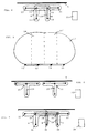
- Figure 4 shows a first embodiment according to the invention in a schematic plan view of the Sound transducers from above. These are preferably the same Way as shown in Figures 1-3, before the goal 5 lying, arranged below the bombardment area.
- Measurement arrangements are also preferred here with four microphones and used in a T-shaped arrangement. The principle of lining up several measuring arrangements and selection of one of them is for any measuring arrangement (number of microphones, arrangement the same) applicable.
- the measurement arrangements are shown in the Example arranged overlapping and combined with each other, so two of the transducers are the two T-shaped Measurement arrangements are common.
- the one T-shaped measuring arrangement with the microphones 13, 12 and 14 on the T-beam and the microphone 11 the T-spread in front of the microphone 12 is provided.
- the T-shaped microphone arrangement with the microphones 12, 14 and 15 on the T-bar and on the microphone 16 provided at the end of the T-spread.
- the microphones can be attached to metal rails in a known manner what will be shown later, which is shown in FIG are only indicated as lines 19.
- lines A and B is the T-shape of the two measuring arrangements highlighted for clarity. These lines do not correspond to any actually existing ones Structure in a real embodiment, but serve only the clarification in the drawing.
- An evaluation device 20 is in a basically known manner connected to the microphones and also serves on known ones Way to calculate shot position.
- Figure 5 accordingly shows the resultant Determination field 17.
- the evaluation device 20 from the runtime differences of all microphones compared to the microphone that receives the first signal delivers that T-measurement arrangement, in which the maturity differences are the smallest. This can be as Sum of the respective runtime differences for each measuring arrangement happen or considering the individual Values.
- the shot position is different in the beginning roughly determined, e.g. to known ones Way in front of the goal a light curtain with optical Transmitters and sensors can be built, which roughly the location of the incoming projectile. Based on these The responsible T-measuring arrangement can then determine the rough position selected, their term differences then in the manner known per se for the exact calculation of the Shot position is used. As a very precise area Determining the shot position gives the sum of the areas 18 and 18 'of the two measuring arrangements.
- the microphones are in a known manner electrical lines with the evaluation unit, e.g. one Computer, connected. There is a line saving Possibility of two microphones in parallel to be connected to the evaluation unit 20 by means of the same lines, since the signal order is clear, so for the microphones 13 and 14 and 12 and 15, so that the microphone signals of the microphones 13 and 14 over the same Go line or those of the microphones 12 and 15.
- FIG. 6 shows a further arrangement, at which two measuring arrangements, also T-shaped in the example, which is also only schematic in the figure are shown and designated only globally as 21 and 22 are placed in front of the target.
- the T measurement arrangements do not overlap and each has four individual microphones represented by dots that are not common to the two measuring arrangements.
- the measuring arrangements follows the one described First, determine which of the measuring arrangements is responsible for the incoming projectile and afterwards the calculation of the shot position based on the measured Term differences.
- FIG. 7 shows a further embodiment, where in front of goal 5 three, each T-shaped in the example, Measuring arrangements are arranged.
- This one too Execution is overlapped and used of individual microphones as common T-arrangements Microphones.
- the first T-shaped measuring arrangement which are also highlighted here by line A. includes the microphones 33, 32, 34 and 31.
- the second Measuring arrangement highlighted by line B comprises the microphones 32, 34, 35 and 36.
- the third measuring arrangement finally, highlighted by line C. the microphones 34, 35, 37 and 38.
- One of those already described Wise for an incoming projectile initially determined by the evaluation device of the T-shaped measuring arrangements A, B or C the most accurate To deliver the result for the shot position detection in the Location is.
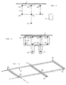
- Figure 8 shows an embodiment according to another aspect of the invention in which a Measuring arrangement with seven microphones arranged in front of target 5 is, so that a sound transducer arrangement with seven microphones. 8 is shown doing so in the same way as those previously explained Figures by drawing a top view of the Sound transducer arrangement or microphone arrangement shown is.
- the individual microphones can in turn by rails or any other elements connected together to precisely determine their position in space.
- the arrangement of the seven microphones is only an example to provide (and can be a double T-shaped arrangement be designated); the measuring arrangement could also any other arrangement of seven (or more) microphones include.
- the microphones with an evaluation device 20 connected which is based on the measured Term differences the determination of the entry point of the projectile through target 5.
- the microphones are here by lines not shown connected to the evaluation device. Also at In this embodiment, two microphones can be used the same line is connected to the evaluation device to save on cables.
- the illustrated The embodiment with seven microphones is used for this Penetration point from flying towards the target Projectiles through the target with good accuracy, even if the idea is very diagonal from the Side or from below or from above.
- the seven Microphones result in six runtime differences for the calculation the location of the Mach's cone of the projectile in the Room.
- the six maturity differences result in the rules of geometry and mathematics six equations, which are nonlinear equations, that cannot be solved in closed form.
- Figure 9 shows a combination of the embodiment of Figure 8 for detecting obliquely incident Projectiles with the embodiment of Figure 4.
- two measuring arrangements with seven microphones as an example arranged next to each other to determine the size of the precisely ascertainable To increase the hit location.
- the form of presentation is again so that the transducers or microphones are shown as dots from above, e.g. again with a rail system together are connected.
- auxiliary lines A, B shown how the individual measuring arrangements through which microphones are formed.
- the microphones are also here via lines, not shown, with the evaluation device 20 connected.
- the first step is determines which of the two adjacent measurement arrangements used to determine the point of passage becomes.
- this can be done using the measuring arrangement seven microphones with the microphones 53, 52, 54, 57, 51, 56 and 60, or the other measuring arrangement with seven Microphones, which are microphones 52, 54, 55, 51, 56, 58 and 59.
- the one of the measurement arrangements for the determination of the passage point is selected (which is done in the same way as above explained with reference to Figures 4 and 5), can be their transit time differences the determination of the passage point respectively. This is done, as already described, based on the six available Term differences.
- Figure 10 shows a perspective view a track arrangement with seven microphones, as in 8 is shown in plan view.
- Figure 10 indicated by broken lines, like this one Rail assembly is expanded when according to the embodiment of Figure 9 is configured.
- rail expansion modules can accordingly be provided be an extension of the rail assembly around three microphones each with the corresponding rails allow.
Landscapes
- Physics & Mathematics (AREA)
- Acoustics & Sound (AREA)
- Engineering & Computer Science (AREA)
- General Engineering & Computer Science (AREA)
- Measurement Of Velocity Or Position Using Acoustic Or Ultrasonic Waves (AREA)
Priority Applications (1)
| Application Number | Priority Date | Filing Date | Title |
|---|---|---|---|
| EP99110512A EP1058083A1 (fr) | 1999-05-31 | 1999-05-31 | Procédé et dispositif d'indication électronique d'emplacements d'impacts |
Applications Claiming Priority (1)
| Application Number | Priority Date | Filing Date | Title |
|---|---|---|---|
| EP99110512A EP1058083A1 (fr) | 1999-05-31 | 1999-05-31 | Procédé et dispositif d'indication électronique d'emplacements d'impacts |
Publications (1)
| Publication Number | Publication Date |
|---|---|
| EP1058083A1 true EP1058083A1 (fr) | 2000-12-06 |
Family
ID=8238277
Family Applications (1)
| Application Number | Title | Priority Date | Filing Date |
|---|---|---|---|
| EP99110512A Withdrawn EP1058083A1 (fr) | 1999-05-31 | 1999-05-31 | Procédé et dispositif d'indication électronique d'emplacements d'impacts |
Country Status (1)
| Country | Link |
|---|---|
| EP (1) | EP1058083A1 (fr) |
Cited By (4)
| Publication number | Priority date | Publication date | Assignee | Title |
|---|---|---|---|---|
| RU2231738C2 (ru) * | 2002-07-22 | 2004-06-27 | Институт прикладной механики УрО РАН | Способ определения внешнебаллистических характеристик полета пуль и снарядов |
| EP2040025A1 (fr) | 2007-09-21 | 2009-03-25 | Saab Ab | Système pour cible avec détermination automatique du point d'impact |
| RU2367885C1 (ru) * | 2008-03-24 | 2009-09-20 | Федеральное государственное унитарное предприятие "Центральный научно-исследовательский институт точного машиностроения" | Устройство для определения координат попадания пуль |
| FR3057367A1 (fr) * | 2016-10-10 | 2018-04-13 | Commissariat A L'energie Atomique Et Aux Energies Alternatives | Dispositif de localisation d'un impact contre une surface interactive, procede et programme d'ordinateur correspondants |
Citations (6)
| Publication number | Priority date | Publication date | Assignee | Title |
|---|---|---|---|---|
| US3678495A (en) * | 1970-02-26 | 1972-07-18 | Technical Management Services | Target indicating system and method |
| CH589835A5 (en) | 1975-03-17 | 1977-11-15 | Walti Hansruedi | Firing target with electronic hit evaluation - has several measuring sensors underneath target area and electronic computer for hit evaluation |
| FR2381271A1 (fr) * | 1977-02-21 | 1978-09-15 | Australasian Training Aids Pty | Appareils electroniques de controle d'un stand de tir |
| DE2921783A1 (de) | 1978-05-30 | 1979-12-06 | Australasian Training Aids Pty | Vorrichtung zur bestimmung der lage der geschossbahn eines geschosses mit ueberschallgeschwindigkeit |
| GB2083177A (en) * | 1979-01-08 | 1982-03-17 | Australasian Training Aids Pty | Improvements in or relating to position determining apparatus |
| WO1987005706A1 (fr) | 1986-03-12 | 1987-09-24 | Ms Instruments Plc | Appareil et procede de mesure de positions |
-
1999
- 1999-05-31 EP EP99110512A patent/EP1058083A1/fr not_active Withdrawn
Patent Citations (6)
| Publication number | Priority date | Publication date | Assignee | Title |
|---|---|---|---|---|
| US3678495A (en) * | 1970-02-26 | 1972-07-18 | Technical Management Services | Target indicating system and method |
| CH589835A5 (en) | 1975-03-17 | 1977-11-15 | Walti Hansruedi | Firing target with electronic hit evaluation - has several measuring sensors underneath target area and electronic computer for hit evaluation |
| FR2381271A1 (fr) * | 1977-02-21 | 1978-09-15 | Australasian Training Aids Pty | Appareils electroniques de controle d'un stand de tir |
| DE2921783A1 (de) | 1978-05-30 | 1979-12-06 | Australasian Training Aids Pty | Vorrichtung zur bestimmung der lage der geschossbahn eines geschosses mit ueberschallgeschwindigkeit |
| GB2083177A (en) * | 1979-01-08 | 1982-03-17 | Australasian Training Aids Pty | Improvements in or relating to position determining apparatus |
| WO1987005706A1 (fr) | 1986-03-12 | 1987-09-24 | Ms Instruments Plc | Appareil et procede de mesure de positions |
Cited By (5)
| Publication number | Priority date | Publication date | Assignee | Title |
|---|---|---|---|---|
| RU2231738C2 (ru) * | 2002-07-22 | 2004-06-27 | Институт прикладной механики УрО РАН | Способ определения внешнебаллистических характеристик полета пуль и снарядов |
| EP2040025A1 (fr) | 2007-09-21 | 2009-03-25 | Saab Ab | Système pour cible avec détermination automatique du point d'impact |
| RU2367885C1 (ru) * | 2008-03-24 | 2009-09-20 | Федеральное государственное унитарное предприятие "Центральный научно-исследовательский институт точного машиностроения" | Устройство для определения координат попадания пуль |
| FR3057367A1 (fr) * | 2016-10-10 | 2018-04-13 | Commissariat A L'energie Atomique Et Aux Energies Alternatives | Dispositif de localisation d'un impact contre une surface interactive, procede et programme d'ordinateur correspondants |
| WO2018069608A1 (fr) * | 2016-10-10 | 2018-04-19 | Commissariat à l'énergie atomique et aux énergies alternatives | Dispositif de localisation d'un impact contre une surface interactive, procede et programme d'ordinateur correspondants |
Similar Documents
| Publication | Publication Date | Title |
|---|---|---|
| DE2807101A1 (de) | Trefferanzeigevorrichtung fuer einen schiessplatz o.dgl. | |
| DE2921783A1 (de) | Vorrichtung zur bestimmung der lage der geschossbahn eines geschosses mit ueberschallgeschwindigkeit | |
| DE19704080C2 (de) | Minensuchgerät | |
| EP0474799B1 (fr) | Procede et dispositif permettant de controler le parallelisme d'axes de corps | |
| DE2738213C2 (de) | Einrichtung zur selbsttätigen elektronischen Ermittlung und Anzeige der Lage von Treffern auf einer Zielfläche | |
| DE69119583T2 (de) | Vorrichtung zur akustischen auswertung einer geschossflugbahn | |
| EP0157397B1 (fr) | Agencement de détermination du point d'impact, de la vitesse et de l'angle d'incidence d'un projectile atteignant une cible à vitesse ultrasonique | |
| CH589835A5 (en) | Firing target with electronic hit evaluation - has several measuring sensors underneath target area and electronic computer for hit evaluation | |
| DE2942355A1 (de) | Vorrichtung zum erfassen des durchganges eines projektils | |
| DE2332158A1 (de) | Leitsystem fuer flugzeugabwehrraketen | |
| EP1464984A1 (fr) | Procédé et programme informatique pour simuler la zone de détection d'un capteur | |
| DE2143116C1 (fr) | ||
| DE2149729C3 (de) | Führungssystem mit sich überlappenden Laserstrahlkeulen | |
| DE4106040C2 (de) | Verfahren und Vorrichtung zum Bestimmen der Geschwindigkeit von Geschossen | |
| DE102019108741A1 (de) | Rauschunterdrückungsvorrichtung für elektromagnetische Messsysteme, Radarmesssysteme und Verwendung desselben | |
| DE3528075A1 (de) | Verfahren und einrichtung zur stereoakustischen trefferablagemessung von geschossen | |
| EP0237714A1 (fr) | Méthode de vol à très basse altitude pour trouver automatiquement le cap | |
| DE4324780C2 (de) | Verfahren und Vorrichtung zur Bestimmung der Neigung zweier Bezugsebenen eines Körpers zueinander | |
| DE4209077C2 (de) | Verfahren zur Entfernungsmessung und Vorrichtung zur Durchführung des Verfahrens | |
| EP4111227A1 (fr) | Dispositif et procédé d'étalonnage d'un capteur numérique | |
| DE3414819C2 (de) | Verfahren und einrichtung zum feststellen und ueberwachen einer abmessung und der lage eines gegebenenfalls bewegten gegenstandes | |
| DE102019134541A1 (de) | Verfahren zur Steuerung eines Mikrofonarrays und Vorrichtung zur Steuerung eines Mikrofonarrays | |
| WO2007045104A1 (fr) | Procede et dispositif pour detecter l'emplacement d'impact d'objets volants sur un champ d'impact defini | |
| DE4106132C2 (de) | Verfahren zum Prüfen einer Gruppenantenne | |
| EP0519315B1 (fr) | Dispositif pour mesurer le profil en hauteur d'un vent au sol |
Legal Events
| Date | Code | Title | Description |
|---|---|---|---|
| PUAI | Public reference made under article 153(3) epc to a published international application that has entered the european phase |
Free format text: ORIGINAL CODE: 0009012 |
|
| AK | Designated contracting states |
Kind code of ref document: A1 Designated state(s): AT BE CH CY DE DK ES FI FR GB GR IE IT LI LU MC NL PT SE |
|
| AX | Request for extension of the european patent |
Free format text: AL;LT;LV;MK;RO;SI |
|
| AKX | Designation fees paid | ||
| STAA | Information on the status of an ep patent application or granted ep patent |
Free format text: STATUS: THE APPLICATION IS DEEMED TO BE WITHDRAWN |
|
| 18D | Application deemed to be withdrawn |
Effective date: 20010607 |
|
| REG | Reference to a national code |
Ref country code: DE Ref legal event code: 8566 |