EP1058087B1 - Détermination de la position d'un bord avec des capteurs répartis par la détermination du point tournant - Google Patents
Détermination de la position d'un bord avec des capteurs répartis par la détermination du point tournant Download PDFInfo
- Publication number
- EP1058087B1 EP1058087B1 EP00110943A EP00110943A EP1058087B1 EP 1058087 B1 EP1058087 B1 EP 1058087B1 EP 00110943 A EP00110943 A EP 00110943A EP 00110943 A EP00110943 A EP 00110943A EP 1058087 B1 EP1058087 B1 EP 1058087B1
- Authority
- EP
- European Patent Office
- Prior art keywords
- sensors
- web
- sensor
- point
- inflection
- Prior art date
- Legal status (The legal status is an assumption and is not a legal conclusion. Google has not performed a legal analysis and makes no representation as to the accuracy of the status listed.)
- Expired - Lifetime
Links
- 238000000034 method Methods 0.000 claims description 20
- 230000003287 optical effect Effects 0.000 claims description 6
- 230000004069 differentiation Effects 0.000 claims description 4
- 230000006870 function Effects 0.000 description 26
- 239000000463 material Substances 0.000 description 6
- 238000004422 calculation algorithm Methods 0.000 description 5
- 238000004364 calculation method Methods 0.000 description 4
- 238000001514 detection method Methods 0.000 description 4
- 239000000126 substance Substances 0.000 description 4
- 230000008901 benefit Effects 0.000 description 2
- 230000008859 change Effects 0.000 description 2
- 230000001419 dependent effect Effects 0.000 description 2
- 238000009795 derivation Methods 0.000 description 2
- 238000010586 diagram Methods 0.000 description 2
- 238000003708 edge detection Methods 0.000 description 2
- 230000000694 effects Effects 0.000 description 2
- 238000005259 measurement Methods 0.000 description 2
- 230000035945 sensitivity Effects 0.000 description 2
- 238000012549 training Methods 0.000 description 2
- 230000004888 barrier function Effects 0.000 description 1
- 230000015572 biosynthetic process Effects 0.000 description 1
- 239000003518 caustics Substances 0.000 description 1
- 238000006243 chemical reaction Methods 0.000 description 1
- 239000004020 conductor Substances 0.000 description 1
- 238000011109 contamination Methods 0.000 description 1
- 238000012937 correction Methods 0.000 description 1
- 230000002349 favourable effect Effects 0.000 description 1
- 239000000835 fiber Substances 0.000 description 1
- 239000007850 fluorescent dye Substances 0.000 description 1
- 239000011521 glass Substances 0.000 description 1
- 230000001771 impaired effect Effects 0.000 description 1
- 238000012886 linear function Methods 0.000 description 1
- 238000004519 manufacturing process Methods 0.000 description 1
- 230000008569 process Effects 0.000 description 1
- 238000012545 processing Methods 0.000 description 1
- 239000004065 semiconductor Substances 0.000 description 1
- 239000004753 textile Substances 0.000 description 1
- 238000012546 transfer Methods 0.000 description 1
- 230000007704 transition Effects 0.000 description 1
Images
Classifications
-
- G—PHYSICS
- G01—MEASURING; TESTING
- G01B—MEASURING LENGTH, THICKNESS OR SIMILAR LINEAR DIMENSIONS; MEASURING ANGLES; MEASURING AREAS; MEASURING IRREGULARITIES OF SURFACES OR CONTOURS
- G01B11/00—Measuring arrangements characterised by the use of optical techniques
- G01B11/02—Measuring arrangements characterised by the use of optical techniques for measuring length, width or thickness
- G01B11/028—Measuring arrangements characterised by the use of optical techniques for measuring length, width or thickness by measuring lateral position of a boundary of the object
-
- B—PERFORMING OPERATIONS; TRANSPORTING
- B65—CONVEYING; PACKING; STORING; HANDLING THIN OR FILAMENTARY MATERIAL
- B65H—HANDLING THIN OR FILAMENTARY MATERIAL, e.g. SHEETS, WEBS, CABLES
- B65H23/00—Registering, tensioning, smoothing or guiding webs
- B65H23/02—Registering, tensioning, smoothing or guiding webs transversely
- B65H23/0204—Sensing transverse register of web
-
- B—PERFORMING OPERATIONS; TRANSPORTING
- B65—CONVEYING; PACKING; STORING; HANDLING THIN OR FILAMENTARY MATERIAL
- B65H—HANDLING THIN OR FILAMENTARY MATERIAL, e.g. SHEETS, WEBS, CABLES
- B65H2553/00—Sensing or detecting means
- B65H2553/10—Sensing or detecting means using fluids, e.g. pneumatics
-
- B—PERFORMING OPERATIONS; TRANSPORTING
- B65—CONVEYING; PACKING; STORING; HANDLING THIN OR FILAMENTARY MATERIAL
- B65H—HANDLING THIN OR FILAMENTARY MATERIAL, e.g. SHEETS, WEBS, CABLES
- B65H2553/00—Sensing or detecting means
- B65H2553/30—Sensing or detecting means using acoustic or ultrasonic elements
-
- B—PERFORMING OPERATIONS; TRANSPORTING
- B65—CONVEYING; PACKING; STORING; HANDLING THIN OR FILAMENTARY MATERIAL
- B65H—HANDLING THIN OR FILAMENTARY MATERIAL, e.g. SHEETS, WEBS, CABLES
- B65H2553/00—Sensing or detecting means
- B65H2553/40—Sensing or detecting means using optical, e.g. photographic, elements
Definitions
- the invention relates to a method for detecting the position a running web according to the preamble of Claim 1 and a device for performing this method according to the preamble of the claim 9.
- DE 34 23 308 C2 describes a photoelectronic sensing device known, in which one light source several, opposite to each other acting receiver parts.
- the receiver parts are made of semiconductor photo elements formed optically on light-collecting Plastic surfaces are coupled.
- Each of these receiver parts covers a specific area of the web, wherein the photo element is a for covering by the web proportional signal.
- the web edge position is by comparing that of the photo elements emitted signals determined with a threshold.
- this Sensing device achievable resolution essentially of Corresponds to the width of the plastic plates. To achieve a high resolution with a large measuring range therefore a very large number of photo elements is required. In addition, in this case there is a very large number of photo elements to be queried in every measuring cycle.
- DE 42 09 546 C2 describes a device for determining the position of the edge of a running material web is known, with the multiple, separately controllable light sources one receiver part is opposite each other.
- This Receiver parts give a proportional to the coverage of the web Signal from that compared to a threshold becomes.
- the comparison result is a microcomputer fed, depending on the comparison result the light sources and receiver parts according to one successive approximation and in this way the position of the web edge is determined.
- To carry out the successive approximation must be a number of Comparison values of the receiver parts with the threshold value stored in a memory unit of the microcomputer become.
- the invention has for its object a method of the type mentioned at the outset to create a high Resolution achieved with a short measuring time.
- a inexpensive device for performing this method be created.
- Each sensor generates a signal that depending on the coverage of the sensor by the web is.
- the signal generated by the sensor is preferably proportional to the coverage by the web.
- each sensor delivers a position of the web edge dependent signal, with the individual sensors in different Areas are arranged in the measuring direction.
- the web is preferably scanned without contact, not even sensitive webs damaged by the sensors. It will also be on this prevents the sensors themselves from edge detection disturb, like this for example with a mechanical edge sensor is the case with spring force presses against the web edge.
- the web edge are those viewed from the center of the web inner sensors completely through the web covered, so that these sensors have a constant idle signal submit.
- the outer sensors are opposite not covered by the web in any way, making it a generate maximum signal.
- the sensors in the area around the Web edge provide signals between the idle signal and the maximum signal.
- the function of signals generated by the sensors from the sensor locations therefore two constant areas with approximately medium edge position different signal levels between which one continuous transition area is provided.
- At extreme Position of the web edge in the area of the innermost or outermost Sensor can be one of the constant ranges too are missing, so that edge determination via threshold values in this case becomes very inaccurate.
- the individual are preferred Sensors equidistant across the web direction distributed so that the sensor location is particularly easy can be determined by numbering the sensors.
- the sensor signals are determined by the sensor number, being the result of the turning point search in this Multiply the case by the mutual distance of the sensors is.
- the turning point can also be from a Function of the sensor signals of values belonging to the Sensor locations are proportional, can be determined. To one to get correctly scaled web edge position, the determined inflection point with the proportionality factor be multiplied. In those cases where only a signal proportional to the edge position is needed, for example in web guiding devices the case may be on a corresponding one Correction of the determined turning point also waived become.
- the sensor is integrated his signal from a given area, so that small area Deposits on the sensor surface are only minimal Have an influence on the signal generated by the sensor. This is particularly the case with heavily linting webs important, because lint originating directly from the web of goods can deposit on the sensor surface. If they had Sensors an effective width below about 1 mm, so every single lint could have full coverage of a sensor cause what is mistakenly called the web edge would be interpreted. Thanks to the extensive training The effective sensor surface can only be deposited lint for an even attenuation of the signals of all Sensors lead, however, to the location of the turning point has no influence. With this measure increased sensitivity to dirt of the edge sensing device reached. Because the turning point is much more accurate can be determined as the distance of the individual sensors, this measure does not affect accuracy the edge determination.
- the detection methods proposed in claim 3 the web cover work without contact and disturb therefore in no way the web run. You can also click on this way, especially sensitive webs are safe be detected without the risk of damage the web or a measurement falsification.
- An optical detection of the web cover takes place either in the reflection process or in the light barrier principle.
- the web of at least illuminated by a light source being light sensitive Receiver either on the opposite of the web Side or next to the light source are provided.
- the web cover could also be on pneumatic Paths can be scanned using air jets, whereby in this case, provide pressure-sensitive sensors are. With an acoustic scanning of the web Sound waves directed against the web by Microphones can be detected.
- a particularly simple and therefore interference-free detection of the inflection point follows from claim 4 the function of the signals from the sensor location twice numerically differentiated and one from the second derivative function Zero determined.
- the one corresponding to the edge position Zero of the second derivative is in the range the greatest slope, i.e. at a maximum value the first derivative. From these conditions, the Edge position determined with little computing effort become.
- the turning point according to claim 5 can also by simple numerical differentiation and numerical Find the maximum of the first derivative function be determined. In this way there is a second differentiation saved, however, the search of the maximum the first derivative function is numerically more complex is.
- this method has the advantage that the condition to search for the absolute maximum without any additional constraint the position of the web edge provides.
- the The turning point is calculated directly from the fit parameters becomes.
- the approximation of the fit function to the signals of the Sensors are preferably made using the minimization method the squares of the deviations of the signals from the corresponding function values of the fit function.
- the turning point can generally be done analytically by two Differentiate and zero the fit function be, so that depending on the fit function a more or less simple formula for calculating the turning point from the Fit parameters can be specified.
- a fit function according to claim 7 Polynomial used, whose coefficients are the fit parameters are. From this polynomial the second one can be very easily Calculate the derivative analytically, so that from the polynomial coefficients the turning point can be determined directly can.
- the signals of the individual are proposed Sensors by the signal of a reference sensor to divide.
- This measure can measuring errors for example, from a changing illuminance originate from the transmitter, be eliminated. Will the Signals from the sensor and the reference sensor are recorded promptly, this can also cause short-term fluctuations in the transmitter be balanced.
- a sensor is preferably used in each case alternately queried with the reference sensor to determine transmitter fluctuations balance as optimally as possible.
- the device according to claim 9 has been implemented of the method according to the invention particularly proven.
- This device has several sensors, each generate a signal dependent on the coverage of the web. These sensors are preferably transverse to the web running direction placed in a row next to each other. Alternatively, you could they also zigzag staggered his. It is important that the individual sensors from one fixed imaginary web edge different distances exhibit. This ensures that each sensor in one certain width range on changes in web edge responds. However, if the sensor is completely removed from the Path covered, it only generates a rest signal. If the sensor is not covered by the web at all, so it generates a maximum active signal.
- the single ones Sensors are via switching means with an analog-to-digital converter connected.
- This switching means that the signals from each sensor are sequential queried and converted into a digital value can.
- These switching means are available with storage means in Active connection in which the digitized values are stored become.
- a turning point detector can be placed on these storage means access that from the function of digitized Values from the sensor locations a turning point determined.
- the digital value calculated by the inflection point detector is output at a digital output and stands thus other devices such as web edge regulators or Display instruments available.
- the senor as a photodetector with assigned plate made of light-collecting plastic to train.
- a fluorescent in the plastic plate Contain substance that is from the light source converts incoming light into longer wave light that spreads preferentially in the plate plane.
- the photo detector is coupled to the front of the plate, so that he is a very strong and therefore insensitive to interference Light signal receives. Due to the occurrence of total reflections the light is distributed on the plate surfaces Light evenly over the entire plate so that the Sensor is exactly proportional to the coverage by the web Signal delivers. It doesn't matter whether the light is evenly distributed or only on a certain one Spot penetrates the plastic plate.
- this element is a body with a Variety of perpendicular to the web Surfaces.
- the element of pipe pieces, parallel walls or a honeycomb structure be educated.
- the item could be from a Row of lenses or a bundle of glass or plastic fibers be educated. It is only important that the Light rays, seen in the direction of detection of the device, are aligned parallel to each other. In the direction of the web seen, however, play different Beam directions of light only a subordinate Role.
- a particularly simple implementation of the switching means for time-delayed query of the sensors results from Claim 12 in the form of an analog multiplexer.
- An analog multiplexer is available as an integrated circuit and thus insensitive to chemicals and elevated Temperatures, such as when processing textiles Material webs occur. So that the generated by the sensors Signals through the non-negligible on-resistance of the analog multiplexer are not falsified, the signals are not considered as voltage but as Transfer current values.
- a subsequent analog-to-digital conversion is to be made possible by the analog multiplexer a current-voltage converter downstream of the one generated voltage proportional to the sensor current.
- the sensitive circuit boards are required to which the sensor electronics are attached to a certain extent To be made dimensionally stretchable. It is therefore according to claim 13 proposed the boards that the sensors wear, at least partially flexible training. It is conceivable, the entire sensors at least one to build flexible board over its entire length. Alternatively, the sensors can also be modular hard boards are housed, with between the individual modules each have a flexible connection, for example in the form of cables.
- the turning point detector provides a circuitry complex device, so that it according to claim 14 it is favorable to train this as a controller.
- a circuitry complex device so that it according to claim 14 it is favorable to train this as a controller.
- the one required is also preferred Analog-digital converter designed as part of the controller, which increases the circuit complexity reduced even further.
- FIG. 15 Turning point detector at least one digital-to-analog converter which may also be part of the Controller can be formed.
- the digital-to-analog converter creates the inflection point and thus the edge position proportional analog signal that directly one Web edge controller can be fed.
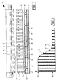
- FIG. 1 shows a sectional illustration of a device 1 for detecting the position of an edge 2 of a web 3.
- the device 1 has a light source 4 in the form of a Fluorescent tube on, the light rays 5, 5 'against the Goods web 3 sends out.
- the edge 2 of the web 3 becomes a smaller or larger proportion of the Light rays 5, 5 'absorbed by the web 3 or reflected while the other part of the light rays 5, 5 'is in no way influenced by the web 3.
- the light beams 5, 5 'then pass an optical one Element 6, made by several perpendicular to the web 3 aligned walls 7 is formed.
- Light rays 5 ', which run at an angle to the walls 7 are from the Walls 7 absorbed so that only those light rays 5 the optical element 6 can pass that approximately run perpendicular to the web 3. That way a sharp edge image through the light rays 5 reached.
- Each sensor 11 consists of a photosensitive element in the form of a photodiode 12, with a photosensitive surface 13 of the photodiode 12 in a bore 14 of a plastic plate 15 is provided.
- the thickness D of the plastic plate 15 is the height of the photosensitive surface 13 Adapted photodiode 12.
- a fluorescent dye is installed in the plastic plate 15, which converts the incident light rays 5 into longer-wave light rays 16.
- These long-wave light rays 16 preferably propagate approximately in the plane of the plastic plate 15 and are therefore totally reflected at the upper and lower boundary surfaces 17 of the plastic plate 15.
- the long-wave light rays 16 therefore emerge primarily from the plastic plate 15 on the end faces 18 and on the wall of the bore 14. This ensures that a relatively large proportion of the light 5 incident in the plastic plate 15 reaches the photosensitive surface 13 of the photodiode 12, so that it emits a correspondingly high photo current.
- the sensors are therefore insensitive to selective contamination.
- the plastic plates 15 are on a common carrier 11 held, preferably opposite the web 3 is sealed. This is especially so in those Important cases in which the device 1 in the wet area is used where the web 3 partly with caustic Chemicals is treated.
- the tight seal of the wearer 20 compared to the web 3 ensures sufficient Protection of the sensor unit 10 against the chemicals.
- the photodiodes 12 are soldered onto boards 21, which are in the Contrary to the carrier 20 composed of several individual parts are.
- this has the advantage of one easier manufacture of the boards 21, in particular for large sensor lengths.
- the boards can 21 expand to a certain extent with respect to the carrier 20, without the sensitive conductor layer on the boards 21 damage. This is especially so in those cases important in which the device 1 of an elevated temperature, for example up to 105 ° C.
- the Connection between the individual boards 21 takes place in the simplest case by a flexible section 22 in Form of a multi-core cable.
- the Entire board 21 made of flexible material, such as a copper-clad Film.
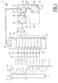
- Figure 2 shows a schematic circuit diagram of the device 1.
- the light 5 emitted by the light source 4 passes the web 3, as well as the optical element 6 and is detected by photodiodes 12.
- the photodiodes 12 are on the cathode side at a reference voltage source 30 connected to the photodiodes 12 a sufficient Apply reverse voltage.
- the photodiodes could 12 can also be switched as photo elements, wherein then resistors to suppress capacitive current peaks are connected in parallel to these.
- the photodiodes 12 are on the anode side with an analog multiplexer 31 connected, which corresponds to the logical levels at its address inputs 32 a selected input 33 connects to an output 34.
- the exit 34 of the analog multiplexer 31 is with a current-voltage converter 35 connected to the output 34 of the analog multiplexer 31 pulls to ground.
- An output 36 of the current-voltage converter 35 is with an analog-to-digital converter 37 connected to the one Digital current generated corresponding digital value.
- These digital values pass into a microcontroller via a signal path 42 39, which initially contains the individual digital values stores a storage unit 40.
- An operating program is stored in the microcontroller 39, that generates addresses for the analog multiplexer 31 and applies this to an address output 41. Also cares this operating program for the control of the analog-digital converter 37 via signal path 42 and reception of the digitized values via signal path 38 Operating program of the microcontroller also causes the storage of the digitized values in the storage unit 40 and the calculation of a turning point from the stored Data. Finally, the operating program ensures for outputting the determined turning point at one Output 43 and for the control of a digital-to-analog converter 44, which converts the digital value at output 43 into a Analog voltage converts and outputs at an analog output 45.
- the one at digital output 43 and at analog output 45 pending value corresponds to the position of edge 2 of the Web 3 and can of other devices, such as Edge controls or display units used become.
- Figure 3 shows a schematic representation of the Sensors 11 determine signals S as a function of the respective Sensor location.
- the signals S of the individual sensors are shown as bars.
- the signals S result together a function 51 from the respective sensor location, which is shown in the form of a curve.
- This function 51 has a turning point W, this results in with sufficient accuracy the location of the edge 2 of the Material web 3, the turning point W regardless of the maximum Signal 53 and from the idle signal 54.
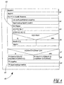
- FIG. 4 shows a first variant of an algorithm 60 for the operating program of the microcontroller 39. Since the Device 1 periodically determine the edge 2 of the web 3 is the operating program in the form of an endless loop 61 trained. At the beginning of the endless loop 61, the MaxS variable is initialized 62 and MaxI.
- a counting loop 63 follows. which run through once for each individual sensor 11 becomes. First, a measurement is made in the counting loop 63 64 performed in which the count variable i to the analog multiplexer 31 output as address and that on the analog-to-digital converter 37 applied voltage value S converted becomes.
- the measured voltage value S is then saved 65, being neighboring by calculating the differences Evaluate the first A and second derivative A2 of the Voltage values S is calculated. It is assumed that the individual sensors 11 to each other in the same Distance are arranged. So the distance is the Sensors 11 from each other only for the formation of the first A and second derivative A2 constant factor, see above that this distance can be disregarded.
- a Maximum search 66 of the first derivative A For this, the determined value of the first derivative A [i] with the variable MaxS compared and in the event that this value is greater than MaxS, as the new maximum of the first derivative A noted.
- the variable then contains MaxI at the end the counting loop 63 the number of that sensor 11 at which the first derivative A [MaxI] is maximum.
- the counting loop 63 is followed by a query 67 in which it determines becomes where the second derivative function A2 one Has a change of sign. Then there is a turning point W from the second derivatives A2 on both sides of the change of sign by linear interpolation between them calculated in step 68. Finally becomes the calculated turning point W in the final output step 69 issued in digital form and into one Analog value changed.
- the inflection point W could also be by interpolation a non-linear function, for example one Higher degree polynomial, which is calculated the accuracy of the inflection point calculation 68 accordingly improved. It is also conceivable instead of interpolation also an approximation of a fit function the method of minimizing the square distances the fit function from the stored values S, A or A2 to make. In this way, errors in the signals S a correspondingly smaller influence on the determination of the turning point W.
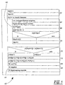
- FIG. 5 shows an alternative algorithm 60 which, in steps 62 to 66, corresponds to the proviso that the second derivative A2 is not calculated.
- a query 70 is carried out in which that side of the maximum of the derivation function A found on which the derivation function A is greatest.
- the Coefficients c and d are the inflection point W of the interpolation polynomial calculated.
- the output step 69 is again identical to the algorithm 60 according to FIG. 4.
Landscapes
- Physics & Mathematics (AREA)
- General Physics & Mathematics (AREA)
- Length Measuring Devices By Optical Means (AREA)
Claims (15)
- Procédé de détection de position d'un bord (2) d'un lé de marchandise (3), se déplaçant, dans lequel le lé de marchandise (3) est balayé par plusieurs capteurs (11) répartis transversalement par rapport au sens de déplacement de la marchandise, qui génère respectivement un signal (S) fonction du recouvrement par le lé de marchandise (3), un signal de sortie numérique et/ou analogique étant émis, caractérisé en ce qu'un point tournant (W) est déterminé à partir de la fonction (51) des signaux (S) des valeurs proportionnelles aux localisations générés par les capteurs (11) et le signal de sortie émis est proportionnel au point tournant (W) déterminé.
- Procédé selon la revendication 1, caractérisé en ce que le capteur (11) intègre sur une plage donnée transversale au sens de déplacement du lé.
- Procédé selon la revendication 1 ou 2, caractérisé en ce que le recouvrement par le lé de marchandise est détecté par voie optique, pneumatique ou acoustique.
- Procédé selon au moins l'une des revendications 1 à 3, caractérisé en ce que le point tournant (W) est déterminé par double différenciation numérique (65) de la fonction (51) des signaux des valeurs proportionnels aux localisations des capteurs générée par les capteurs (11), un point zéro de la seconde fonction dérivée (A2) déterminée étant calculé par interpolation ou approximation (68).
- Procédé selon au moins l'une des revendications 1 à 3, caractérisé en ce que le point tournant (W) est déterminé par différenciation numérique (65) de la fonction (51) des signaux (S) de valeurs proportionnelles aux localisations de capteurs générée par les capteurs (11), le maximum de la fonction dérivée (A) étant calculé par interpolation ou approximation.
- Procédé selon au moins l'une des revendications 1 à 3, caractérisé en ce que le point tournant (W) est déterminé par interpolation ou approximation (68) d'une fonction d'approximation à la fonction (51) des signaux (S) de valeurs proportionnelles aux localisations de capteurs générée par les capteurs (11), le point tournant (W) étant calculé à partir des paramètres de l'approximation (c, d) déterminés.
- Procédé selon la revendication 6, caractérisé en ce que la fonction d'approximation est un polynôme.
- Procédé selon au moins l'une des revendications 1 à 6, caractérisé en ce que le signal (S) du capteur (11) est cadré avec un signal (S) d'un capteur de référence, les deux signaux (S) étant détectés en temps réel.
- Dispositif de détection de détection de position d'un bord (2) d'un lé de marchandise (3), se déplaçant, dans lequel le lé de marchandise (3) est balayé par plusieurs capteurs (11) répartis transversalement par rapport au sens de déplacement de la marchandise, qui génèrent respectivement un signal (S) fonction du recouvrement par le lé de marchandise (3), et qui sont en liaison de coopération par l'intermédiaire de moyens de commutation (31) avec un convertisseur analogique-numérique (37), sont associés au moyen de mémorisation (40) pour mémoriser les valeurs numérisées (S), caractérisé en ce que les moyens de mémorisation (40) sont en liaison de coopération avec un détecteur de point tournant (39) déterminant un point tournant (W) à partir de la fonction (1) des valeurs numérisées (S) de valeurs proportionnelles aux localisations de capteurs.
- Dispositif selon la revendication 9, caractérisé en ce que le capteur (11) présente une plaque (15) en matière plastique collectant la lumière, à laquelle est associé un détecteur photo-électrique (12), au moins une source de lumière (4) étant prévue en regard des capteurs (11).
- Dispositif selon la revendication 10, caractérisé en ce qu'entre la source de lumière (4) et les capteurs (11) est prévu un élément (6) parallélisant des rayons lumineux (5, 5').
- Dispositif selon au moins l'une des revendications 9 à 11, caractérisé en ce que les moyens de commutation (31) sont constitués d'au moins un multiplexeur analogique (31), en aval duquel est monté au moins un convertisseur de courant-tension (35).
- Dispositif selon au moins l'une des revendications 9 à 12, caractérisé en ce que les capteurs (11) sont montés sur des platines (21) conçues flexibles au moins partiellement.
- Dispositif selon au moins l'une des revendications 9 à 13, caractérisé en ce que le détecteur de point tournant (39) et/ou le convertisseur analogique-numérique (37) est constitué par au moins un micro-contrôleur (46).
- Dispositif selon au moins l'une des revendications 9 à 14, caractérisé en ce qu'en aval du détecteur de point tournant (39) est monté au moins un convertisseur analogique-numérique (44).
Applications Claiming Priority (2)
| Application Number | Priority Date | Filing Date | Title |
|---|---|---|---|
| DE19924798 | 1999-05-29 | ||
| DE19924798A DE19924798C1 (de) | 1999-05-29 | 1999-05-29 | Verfahren und Vorrichtung zur Lageerfassung einer Kante von einer laufenden Warenbahn |
Publications (2)
| Publication Number | Publication Date |
|---|---|
| EP1058087A1 EP1058087A1 (fr) | 2000-12-06 |
| EP1058087B1 true EP1058087B1 (fr) | 2001-12-12 |
Family
ID=7909694
Family Applications (1)
| Application Number | Title | Priority Date | Filing Date |
|---|---|---|---|
| EP00110943A Expired - Lifetime EP1058087B1 (fr) | 1999-05-29 | 2000-05-25 | Détermination de la position d'un bord avec des capteurs répartis par la détermination du point tournant |
Country Status (3)
| Country | Link |
|---|---|
| US (1) | US6348696B1 (fr) |
| EP (1) | EP1058087B1 (fr) |
| DE (2) | DE19924798C1 (fr) |
Families Citing this family (13)
| Publication number | Priority date | Publication date | Assignee | Title |
|---|---|---|---|---|
| DE10223754A1 (de) * | 2002-05-28 | 2004-01-22 | Siemens Ag | Rundstrickmaschine mit optischem oder akustischem Sensorelement sowie Verfahren zum Betreiben einer derartigen Rundstrickmaschine |
| DE10312872A1 (de) * | 2003-03-22 | 2004-10-14 | Nexpress Solutions Llc | Verfahren und Sensoreinrichtung zum Erfassen eines Gegenstands |
| GB2424269A (en) * | 2004-04-01 | 2006-09-20 | Robert Michael Lipman | Control apparatus |
| US7415881B2 (en) * | 2004-08-19 | 2008-08-26 | Fife Corporation | Ultrasonic sensor system for web-guiding apparatus |
| US7379194B2 (en) * | 2005-10-11 | 2008-05-27 | Pitney Bowes Inc. | Method and system for determining mail piece dimensions using swept laser beam |
| US8355581B2 (en) * | 2007-03-06 | 2013-01-15 | Advanced Vision Technology (Avt) Ltd. | System and method for detecting the contour of an object on a moving conveyor belt |
| DE102009022316B3 (de) * | 2009-05-22 | 2010-08-19 | Eastman Kodak Company | Verfahren und Vorrichtung zur Erkennung einer Substratkante in einer Druckmaschine |
| US8666188B2 (en) * | 2011-03-23 | 2014-03-04 | Xerox Corporation | Identifying edges of web media using textural contrast between web media and backer roll |
| US9415963B2 (en) | 2013-01-30 | 2016-08-16 | Fife Corporation | Sensor controller for interpreting natural interaction sensor for web handling |
| EP2876467A1 (fr) | 2013-11-25 | 2015-05-27 | Sick Ag | Barrière lumineuse |
| DE102017010880A1 (de) * | 2017-11-24 | 2019-05-29 | Texmag Gmbh Vertriebsgesellschaft | Sensor zum Erfassen mindestens einer Kante einer laufenden Warenbahn |
| DE102020104931B4 (de) * | 2020-02-25 | 2021-11-18 | Balluff Gmbh | Verfahren und Vorrichtung zur Kantenerkennung eines Objekts |
| TWI790803B (zh) * | 2020-11-02 | 2023-01-21 | 財團法人工業技術研究院 | 紡織品檢測模組、紡織品分選系統及其使用方法 |
Family Cites Families (19)
| Publication number | Priority date | Publication date | Assignee | Title |
|---|---|---|---|---|
| FR2036090A5 (fr) * | 1969-03-04 | 1970-12-24 | Cetih | |
| US3907439A (en) * | 1973-08-14 | 1975-09-23 | Zygo Corp | Edge-sensing with a scanning laser beam |
| JPS5081358A (fr) * | 1973-11-20 | 1975-07-02 | ||
| JPS55112585A (en) * | 1979-02-22 | 1980-08-30 | Konishiroku Photo Ind Co Ltd | Photo detection unit of moving object |
| US4393313A (en) * | 1981-04-29 | 1983-07-12 | Binks Industries, Inc. | Width detector system |
| DE3317057C2 (de) * | 1983-05-10 | 1987-04-02 | Erhardt + Leimer GmbH, 8900 Augsburg | Fotoelektronische Fühleinrichtung |
| DE3423308C2 (de) * | 1984-06-23 | 1986-06-19 | Erhardt & Leimer GmbH, 8900 Augsburg | Fotoelektronische Fühleinrichtung |
| DE3825295C2 (de) * | 1988-07-26 | 1994-05-11 | Heidelberger Druckmasch Ag | Vorrichtung zur Erfassung der Position einer Papierkante |
| US4991761A (en) * | 1988-10-31 | 1991-02-12 | Web Printing Controls Co., Inc. | Web guide apparatus |
| DE3900928C1 (fr) * | 1989-01-14 | 1990-06-21 | Erhardt + Leimer Gmbh, 8900 Augsburg, De | |
| DE58901190D1 (de) * | 1989-04-12 | 1992-05-21 | Landis & Gyr Betriebs Ag | Anordnung zur messung einer spurabweichung einer bewegbaren folienbahn. |
| EP0532933B1 (fr) * | 1991-08-21 | 1995-11-02 | Tokyo Seimitsu Co.,Ltd. | Dispositif pour détecter la position d'une lame |
| DE4203947C2 (de) * | 1992-02-11 | 1995-01-26 | Bst Servo Technik Gmbh | Verfahren zum Einstellen eines die Bahnkante einer laufenden Materialbahn berührungsfrei erfassenden Fühlers |
| DE4209546C2 (de) * | 1992-03-24 | 1996-04-11 | Elmeg | Vorrichtung zum Ermitteln der Lage der Kante einer laufenden Materialbahn |
| DE4444079C2 (de) * | 1994-12-10 | 1998-03-19 | Koenig & Bauer Albert Ag | Verfahren und Vorrichtung zur Durchführung dieses Verfahrens zum Messen der Lage einer Kante von einer Bahn oder einem Bogen |
| DE19500822C1 (de) * | 1995-01-13 | 1996-03-21 | Erhardt & Leimer Gmbh | Ultraschall-Kantenfühler zur Erfassung der Bahnkante einer Warenbahn |
| IT1276785B1 (it) * | 1995-06-26 | 1997-11-03 | Alberto Pietro | Dispositivo per misurare tessuti |
| DE19620642C2 (de) * | 1996-05-22 | 2002-10-10 | Precitec Kg | Kantensensor |
| US6175419B1 (en) * | 1999-03-24 | 2001-01-16 | Fife Corporation | Light sensor for web-guiding apparatus |
-
1999
- 1999-05-29 DE DE19924798A patent/DE19924798C1/de not_active Expired - Fee Related
-
2000
- 2000-05-24 US US09/577,801 patent/US6348696B1/en not_active Expired - Lifetime
- 2000-05-25 DE DE50000056T patent/DE50000056D1/de not_active Expired - Lifetime
- 2000-05-25 EP EP00110943A patent/EP1058087B1/fr not_active Expired - Lifetime
Also Published As
| Publication number | Publication date |
|---|---|
| EP1058087A1 (fr) | 2000-12-06 |
| DE50000056D1 (de) | 2002-01-24 |
| US6348696B1 (en) | 2002-02-19 |
| DE19924798C1 (de) | 2001-01-11 |
Similar Documents
| Publication | Publication Date | Title |
|---|---|---|
| EP1058087B1 (fr) | Détermination de la position d'un bord avec des capteurs répartis par la détermination du point tournant | |
| DE2521037C3 (de) | Verfahren und Einrichtung zur Messung und/oder Überwachung der Gleichförmigkeit der Oberfläche eines Werkstückes | |
| DE102017106380B4 (de) | Optoelektronischer Sensor und Verfahren zum Erfassen von Objekten | |
| DE3816943C2 (fr) | ||
| DE19500822C1 (de) | Ultraschall-Kantenfühler zur Erfassung der Bahnkante einer Warenbahn | |
| CH693549A5 (de) | Opto-elektronischer Sensor. | |
| DE4211875A1 (de) | Optischer Abstandssensor | |
| DE2364046A1 (de) | Beruehrungsfreie laengenmesseinrichtung | |
| DE112007000959B4 (de) | Detektieren der Position einer Kante einer Bahn | |
| DE69017756T2 (de) | Infrarotanalyseverfahren. | |
| DE19964539B4 (de) | Optoelektronische Vorrichtung zum Erfassen von Objekten | |
| DE3340924C2 (fr) | ||
| DE69900628T2 (de) | Verfahren zum Bestimmen interferometrischer Dickenprofile eines bewegten Materials unter Beibehaltung seiner Flachheit | |
| DE69315686T2 (de) | Winkel-detektion | |
| EP3408609A1 (fr) | Procédé de mesure et dispositif de mesure pour determiner un épaisseur de matière ou une épaisseur de couche d'un objet de test | |
| DE1804600A1 (de) | Einrichtung zur Dickenmessung mit Ultraschall | |
| DE3200508C2 (fr) | ||
| EP2228622A2 (fr) | Procédé et dispositif de mesure de la position des bords d'une bande de matériau | |
| DE19921309A1 (de) | Abtasteinheit für eine optische Positionsmeßeinrichtung | |
| DE19913800C2 (de) | Anordnung zur Auswertung schmalbandiger optischer Signale | |
| EP2013605A2 (fr) | Dispositif de détermination de la rigidité de matériaux flexibles | |
| DE102005062320A1 (de) | Optoelektronische Vorrichtung | |
| DE10317447A1 (de) | Verfahren und Sensoreinrichtung zum Erfassen von Farben | |
| DE4133125C1 (fr) | ||
| EP0143165B1 (fr) | Senseur de distance pour mesurer la distance d'un objet proche |
Legal Events
| Date | Code | Title | Description |
|---|---|---|---|
| PUAI | Public reference made under article 153(3) epc to a published international application that has entered the european phase |
Free format text: ORIGINAL CODE: 0009012 |
|
| AK | Designated contracting states |
Kind code of ref document: A1 Designated state(s): CH DE FR IT LI |
|
| AX | Request for extension of the european patent |
Free format text: AL;LT;LV;MK;RO;SI |
|
| 17P | Request for examination filed |
Effective date: 20001124 |
|
| GRAG | Despatch of communication of intention to grant |
Free format text: ORIGINAL CODE: EPIDOS AGRA |
|
| GRAG | Despatch of communication of intention to grant |
Free format text: ORIGINAL CODE: EPIDOS AGRA |
|
| GRAH | Despatch of communication of intention to grant a patent |
Free format text: ORIGINAL CODE: EPIDOS IGRA |
|
| 17Q | First examination report despatched |
Effective date: 20010516 |
|
| AKX | Designation fees paid |
Free format text: CH DE FR IT LI |
|
| GRAH | Despatch of communication of intention to grant a patent |
Free format text: ORIGINAL CODE: EPIDOS IGRA |
|
| GRAA | (expected) grant |
Free format text: ORIGINAL CODE: 0009210 |
|
| AK | Designated contracting states |
Kind code of ref document: B1 Designated state(s): CH DE FR IT LI |
|
| REG | Reference to a national code |
Ref country code: CH Ref legal event code: EP |
|
| REF | Corresponds to: |
Ref document number: 50000056 Country of ref document: DE Date of ref document: 20020124 |
|
| REG | Reference to a national code |
Ref country code: CH Ref legal event code: NV Representative=s name: TROESCH SCHEIDEGGER WERNER AG |
|
| PLBQ | Unpublished change to opponent data |
Free format text: ORIGINAL CODE: EPIDOS OPPO |
|
| PLBI | Opposition filed |
Free format text: ORIGINAL CODE: 0009260 |
|
| PLBF | Reply of patent proprietor to notice(s) of opposition |
Free format text: ORIGINAL CODE: EPIDOS OBSO |
|
| 26 | Opposition filed |
Opponent name: BST INTERNATIONAL GMBH Effective date: 20020911 |
|
| PLBF | Reply of patent proprietor to notice(s) of opposition |
Free format text: ORIGINAL CODE: EPIDOS OBSO |
|
| PLBF | Reply of patent proprietor to notice(s) of opposition |
Free format text: ORIGINAL CODE: EPIDOS OBSO |
|
| RIN2 | Information on inventor provided after grant (corrected) |
Inventor name: SEIBOLD, HANS Inventor name: SCHWARZ, NORBERT Inventor name: ALT, GERHARD Inventor name: HAEUSSLER, HARALD Inventor name: BRUNNER, GERHARD |
|
| PGFP | Annual fee paid to national office [announced via postgrant information from national office to epo] |
Ref country code: CH Payment date: 20040729 Year of fee payment: 5 |
|
| PG25 | Lapsed in a contracting state [announced via postgrant information from national office to epo] |
Ref country code: CH Free format text: LAPSE BECAUSE OF NON-PAYMENT OF DUE FEES Effective date: 20050531 Ref country code: LI Free format text: LAPSE BECAUSE OF NON-PAYMENT OF DUE FEES Effective date: 20050531 |
|
| REG | Reference to a national code |
Ref country code: CH Ref legal event code: PL |
|
| PLBP | Opposition withdrawn |
Free format text: ORIGINAL CODE: 0009264 |
|
| PLBD | Termination of opposition procedure: decision despatched |
Free format text: ORIGINAL CODE: EPIDOSNOPC1 |
|
| PLBM | Termination of opposition procedure: date of legal effect published |
Free format text: ORIGINAL CODE: 0009276 |
|
| STAA | Information on the status of an ep patent application or granted ep patent |
Free format text: STATUS: OPPOSITION PROCEDURE CLOSED |
|
| 27C | Opposition proceedings terminated |
Effective date: 20070701 |
|
| PLAB | Opposition data, opponent's data or that of the opponent's representative modified |
Free format text: ORIGINAL CODE: 0009299OPPO |
|
| REG | Reference to a national code |
Ref country code: FR Ref legal event code: PLFP Year of fee payment: 17 |
|
| REG | Reference to a national code |
Ref country code: FR Ref legal event code: PLFP Year of fee payment: 18 |
|
| PGFP | Annual fee paid to national office [announced via postgrant information from national office to epo] |
Ref country code: FR Payment date: 20170522 Year of fee payment: 18 |
|
| PGFP | Annual fee paid to national office [announced via postgrant information from national office to epo] |
Ref country code: IT Payment date: 20170531 Year of fee payment: 18 |
|
| PGFP | Annual fee paid to national office [announced via postgrant information from national office to epo] |
Ref country code: DE Payment date: 20170721 Year of fee payment: 18 |
|
| REG | Reference to a national code |
Ref country code: DE Ref legal event code: R119 Ref document number: 50000056 Country of ref document: DE |
|
| PG25 | Lapsed in a contracting state [announced via postgrant information from national office to epo] |
Ref country code: DE Free format text: LAPSE BECAUSE OF NON-PAYMENT OF DUE FEES Effective date: 20181201 Ref country code: FR Free format text: LAPSE BECAUSE OF NON-PAYMENT OF DUE FEES Effective date: 20180531 Ref country code: IT Free format text: LAPSE BECAUSE OF NON-PAYMENT OF DUE FEES Effective date: 20180525 |