EP1059023B1 - Mähdrescher - Google Patents
Mähdrescher Download PDFInfo
- Publication number
- EP1059023B1 EP1059023B1 EP00111362A EP00111362A EP1059023B1 EP 1059023 B1 EP1059023 B1 EP 1059023B1 EP 00111362 A EP00111362 A EP 00111362A EP 00111362 A EP00111362 A EP 00111362A EP 1059023 B1 EP1059023 B1 EP 1059023B1
- Authority
- EP
- European Patent Office
- Prior art keywords
- sieve
- threshing
- combine harvester
- segment
- portions
- Prior art date
- Legal status (The legal status is an assumption and is not a legal conclusion. Google has not performed a legal analysis and makes no representation as to the accuracy of the status listed.)
- Expired - Lifetime
Links
- 238000007689 inspection Methods 0.000 claims description 7
- 230000002035 prolonged effect Effects 0.000 claims 1
- 238000004140 cleaning Methods 0.000 description 2
- 238000012423 maintenance Methods 0.000 description 2
- 238000000926 separation method Methods 0.000 description 2
- 230000008878 coupling Effects 0.000 description 1
- 238000010168 coupling process Methods 0.000 description 1
- 238000005859 coupling reaction Methods 0.000 description 1
- 238000009434 installation Methods 0.000 description 1
- 238000012216 screening Methods 0.000 description 1
Images


Classifications
-
- A—HUMAN NECESSITIES
- A01—AGRICULTURE; FORESTRY; ANIMAL HUSBANDRY; HUNTING; TRAPPING; FISHING
- A01F—PROCESSING OF HARVESTED PRODUCE; HAY OR STRAW PRESSES; DEVICES FOR STORING AGRICULTURAL OR HORTICULTURAL PRODUCE
- A01F12/00—Parts or details of threshing apparatus
- A01F12/18—Threshing devices
- A01F12/26—Multi-part threshing concaves
Definitions
- the invention relates to a combine harvester with a revision opening Threshing mechanism housing, an inclined conveyor that conveys the threshed material, one transversely to the direction of travel built-in threshing unit, consisting of a threshing drum and a Threshing basket, which is equipped with a sieve covering, which consists of several, abutting one another lengthways Covering sections.
- the width is that of the material to be transported Inclined conveyor smaller than the width of the threshing drum and the concave.
- the inspection opening is closed by means of a removable flap and lies above the outlet end of the feeder. It is used, for example, for screen work for maintenance work the concave on the threshing housing.
- the concave is divided lengthwise so that individual screen covering sections are formed that can be removed one after the other from the threshing mechanism housing.
- the concave as a whole is suspended on a horizontal axis, and can be used a boom can be lowered from the operating position into a non-operating position and be pivoted back into the operating position in the reverse manner.
- the diameter of the Threshing drum To increase the performance of a combine, it is necessary to change the diameter of the Threshing drum to increase compared to the previously known designs. It follows that the concave surrounding the drum by a certain angle in the circumferential direction the threshing drum gets longer. It is then no longer possible to use the individual screen covering sections in succession on the narrow space of the threshing mechanism housing through the Removing the inspection opening.
- the invention has for its object to propose a solution that in a combine of the type described in more detail at the outset, with a comparison with previous versions threshing drum enlarged in diameter at least one removal of the Screen covering sections is possible while maintaining the limited installation space.
- sieve covering is proposed according to claim 1, in which the of several sieve covering sections formed screening to adjust to the diameter of the threshing drum the wrapping of the threshing drum has a sieve segment that enlarges through the sieve covering, which is connected to the screen covering sections without gaps.
- the mutually assigned transverse edges of the screen covering sections and the transverse edge of the sieve segment can be firmly connected to one another.
- the transverse edges of the screen covering sections and the transverse edge of the sieve segment in a form-fitting manner but detachably with one another are connected.
- the positive connection should be designed so that no mechanical Fasteners are necessary, and that to release the connection none special tools are necessary.
- the positive connection could for example be designed so that one transverse edge is U-shaped and the other transverse edge is angular and in the U-shaped transverse edge is designed to engage.
- the sieve segment in which the sieve segment is also removed from the threshing mechanism housing it is intended that the sieve segment is one of the number of sieve cover sections corresponding number of sub-segments with the same width as that Screen covering sections is formed and that the screen covering sections and the sub-segments rotatable, but firmly connected.
- the attached subsegment is then dragged along. Because their position to each other can be changed by the rotatable coupling, each sieve segment section can be removed with the attached sub-segment through the inspection opening.
- the additional sieve segment seen in the direction of flow of the threshed material, behind the screen covering sections.
- the rotatable connection for example is granted by hinges, it is possible that the subsegments of the sieve segment in Seen the flow direction of the crop, are also arranged in front of the screen covering sections.
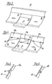
- FIG. 1 and 2 show the front wall 1 of a combine harvester, not shown Threshing mechanism housing, part of the cleaning device 2, which opens through the front wall 1 Inclined conveyor 3 and an inspection opening 4 arranged above it with a Closing flap 4a.
- This is suspended in two lateral studs 5 below.
- the Threshing mechanism housing is the threshing drum 6, whose axis is transverse to the direction of travel runs.
- a curved part extends around the lower right part of the drum circumference Threshing basket 7, which is arranged in its rear edge region and parallel to the drum axis Pin 8 is pivotally mounted.
- the front area it is suspended from two handlebar rods 9, the other ends of an operating lever 11 mounted in a bearing 10 are articulated.
- the screen covering of the concave 7 is in two different versions shown. Thereafter, the screen covering consists in the exemplary embodiment shown three screen covering sections 12, 13 and 14, which are lined up in the axial direction of the threshing drum 6 are. By a sufficient wrap angle for the threshing drum 6 can be achieved, in the illustrated embodiment, a sieve segment 15 with the sieve covering sections 12, 13, 14 firmly connected. The width of the sieve segment matches the overall width of concave 7 match. It can be seen in particular from FIGS. 1 and 2 that the sieve segment 15 wrapped around the threshing drum 6 by a sufficiently large angle becomes.
- the sieve segment 15 consists of three individual segments 15a, 15b, 15c. Each individual segment 15a, 15b, 15c is by two hinges 16 hingedly connected to the associated screen covering section 12, 13, 14. at 3, the sieve segment 15 is formed in one piece.
- the sieve segment 15 is positively connected to the sieve covering sections 12, 13, 14, like that Figure 6 shows. This makes it possible for the connection to be made without mechanical connecting elements can be produced and that for removing the screen covering sections 12, 13, 14 no tools are necessary.
- the positive connection is shown in the embodiment reached in which the edges of the screen covering sections assigned to the screen segment 15 12, 13, 14 are U-shaped and open towards the threshing drum 6.
- the assigned edge of the screen segment 15 is angular, so that they are in the U-shaped Area of each screen covering section 12, 13, 14 protrudes.
- the closing flap 4a is first removed. Then the concave is in the lower position by means of the actuating lever 11 pivoted, as indicated in dash-dotted lines in FIG. 1 and in FIG. 2 is drawn in solid lines. Then the middle screen covering section 13 is first raised and then pulled forward as shown in Figure 2. The intermediate positions this screen covering section 13 are represented by the reference numerals 13 'and 13 ".
- the two lateral screen covering sections 12, 14 are removed in the same way, must first be pushed in the middle, as indicated by the arrows. at 4, the individual segments 15 a, 15b, 15c removed simultaneously with the associated screen covering sections 12, 13, 14, since the by the articulated connection it is possible that they are pivoted against each other. at the embodiment according to FIG.
- the invention is not restricted to the exemplary embodiments shown. It is essential that the concave 7 consists of at least two screen covering sections 12, 13, and that for Enlargement of the sieve area, the sieve segment 15 is connected to the sieve covering sections. In the embodiment according to FIG. 4, it is not necessary that the sieve segment 15 in Seen the direction of flow of the threshed material, arranged behind the screen covering sections 12, 13, 14 is, but it could also be in front of it.
Landscapes
- Life Sciences & Earth Sciences (AREA)
- Environmental Sciences (AREA)
- Threshing Machine Elements (AREA)
- Preparation Of Compounds By Using Micro-Organisms (AREA)
- Tires In General (AREA)
Description
- Figur 1
- Das Dreschwerk des erfindungsgemäßen Mähdreschers und des Auslaufseitigen Endes des Schrägförderers im Vertikalschnitt;
- Figur 2
- eine der Figur 1 entsprechende Darstellung, jedoch mit abgesenktem Dreschkorb und die Entnahme eines Siebbelagabschnittes in verschiedenen Stellungen zeigend;
- Figur 3
- den Dreschkorb des erfindungsgemäßen Mähdreschers in einer ersten Ausführung;
- Figur 4
- eine weitere Ausführung des Dreschkorbes des erfindungsgemäßen . Mähdreschers;
- Figur 5
- einen Schnitt längs der Linie V-V in der Figur 4 und
- Figur 6
- einen Schnitt längs der Linie VI-VI in der Figur 3.
- 1 -
- Frontwand
- 2 -
- Reinigungsvorrichtung
- 3 -
- Schrägförderer
- 4 -
- Revisionsöffnung
- 4a
- Verschließklappe
- 5 -
- Stehzapfen
- 6 -
- Dreschtrommel
- 7 -
- Dreschkorb
- 8 -
- Zapfen
- 9 -
- Lenkerstab
- 10 -
- Lager
- 11 -
- Betätigungshebel
- 12 -
- Siebbelagabschnitt
- 13 -
- Siebbelagabschnitt
- 13'
- " "
- 13"
- " "
- 14 -
- Siebbelagabschnitt
- 15 -
- Siebsegment
- 15a -
- Einzelsegment
- 15b -
- Einzelsegment
- 15c -
- Einzelsegment
- 16 -
- Scharnier
Claims (7)
- Mähdrescher mit einem, eine Revisionsöffnung aufweisenden Dreschwerkgehäuse, einem das Dreschgut fördernden Schrägförderer, einem quer zur Fahrrichtung eingebauten Dreschwerk, bestehend aus einer Dreschtrommel und einem Dreschkorb, der mit einem Siebbelag ausgerüstet ist, der aus mehreren, quer zur Gutflußrichtung aneinanderstoßenden Siebbelagsabschnitten besteht,
dadurch gekennzeichnet, daß der Siebbelag einen die Umschlingung der Dreschtrommel (6) durch den Siebbelag vergrößerndes, die Breite der aneinanderstoßenden Siebabschnitte überdeckendes Siebsegment (15) aufweist, welches mit den mehreren Siebbelagsabschnitten (12, 13, 14), lösbar verbunden ist. - Mähdrescher mit einem, eine Revisionsöffnung aufweisenden Dreschwerkgehäuse, einem das Dreschgut fördernden Schrägförderer, einem quer zur Fahrtrichtung eingebauten Dreschwerk, bestehend aus einer Dreschtrommel und einem Dreschkorb, der mit einem Siebbelag ausgerüstet ist, der aus mehreren, quer zur Gutflußrichtung aneinanderstoßenden Siebelagsabschnitten besteht,
dadurch gekennzeichnet: daß jeder der Siebelagsabschnitte (12,13,14,) über eine gelenkige Verbindung mit einem gleichbreiten Siebsegment (15a, b c) verlängert ist. - Mähdrescher nach Anspruch 2,
dadurch gekennzeichnet, daß das Siebsegment (15) aus einer der Anzahl der Siebbelagsabschnitte (12, 13, 14) entsprechenden Stückzahl von Einzelsegmenten (15a, 15b, 15c) gebildet ist, und die Einzelsegmente (15a, 15b, 15c) drehbeweglich, jedoch fest, vorzugsweise durch Scharniere (16), mit den Siebbelagabschnitten (12, 13, 14) verbunden sind. - Mähdrescher nach den Ansprüchen 2 und 3,
dadurch gekennzeichnet, daß die zugeordneten Querränder der Siebbelagsabschnitte (12, 13, 14) und des Siebsegmentes (15;15a,b,c,) formschlüssig, jedoch lösbar miteinander verbunden sind. - Mähdrescher nach den Ansprüchen 2 bis 4,
dadurch gekennzeichnet, daß ein Querrand U-förmig und der andere Querrand winkelförmig und in den U-förmigen Rand eingreifend ausgebildet ist. - Mähdrescher nach den Ansprüchen 2 bis 5
dadurch gekennzeichnet, daß die Ränder der Siebbelagsabschnitte (12, 13, 14) U-förmig gestaltet, und die zugeordneten Ränder der Siebsegmente (15a, b, c) winkelförmig gestaltet sind. - Mähdrescher nach einem oder mehreren der vorhergehenden Ansprüche 1 bis 6,
dadurch gekennzeichnet, daß das bzw. die Siebsegment / e (15), (15a, b, c) in Flußrichtung des Dreschgutes gesehen, direkt hinter den Siebbelagsabschnitten (12, 13, 14) angeordnet ist bzw. sind.
Priority Applications (1)
| Application Number | Priority Date | Filing Date | Title |
|---|---|---|---|
| DK00111362T DK1059023T3 (da) | 1999-06-10 | 2000-05-26 | Mejetærsker |
Applications Claiming Priority (2)
| Application Number | Priority Date | Filing Date | Title |
|---|---|---|---|
| DE19926365A DE19926365A1 (de) | 1999-06-10 | 1999-06-10 | Mähdrescher |
| DE19926365 | 1999-06-10 |
Publications (3)
| Publication Number | Publication Date |
|---|---|
| EP1059023A2 EP1059023A2 (de) | 2000-12-13 |
| EP1059023A3 EP1059023A3 (de) | 2002-06-12 |
| EP1059023B1 true EP1059023B1 (de) | 2004-08-04 |
Family
ID=7910721
Family Applications (1)
| Application Number | Title | Priority Date | Filing Date |
|---|---|---|---|
| EP00111362A Expired - Lifetime EP1059023B1 (de) | 1999-06-10 | 2000-05-26 | Mähdrescher |
Country Status (6)
| Country | Link |
|---|---|
| US (1) | US6398639B1 (de) |
| EP (1) | EP1059023B1 (de) |
| AT (1) | ATE272306T1 (de) |
| BR (1) | BR0002618A (de) |
| DE (2) | DE19926365A1 (de) |
| DK (1) | DK1059023T3 (de) |
Cited By (2)
| Publication number | Priority date | Publication date | Assignee | Title |
|---|---|---|---|---|
| US20210360860A1 (en) * | 2017-12-05 | 2021-11-25 | Brian Robertson | Concave cover plate system and methods |
| US11997952B2 (en) | 2017-12-05 | 2024-06-04 | Brian Robertson | Automated, dynamic concave cover plate system and methods |
Families Citing this family (18)
| Publication number | Priority date | Publication date | Assignee | Title |
|---|---|---|---|---|
| DE10027450A1 (de) * | 2000-06-02 | 2002-01-03 | Same Deutz Fahr Spa | Dreschkorb für einen Mähdrescher mit Segmentierung |
| DE10116754A1 (de) | 2001-04-04 | 2002-10-10 | Claas Selbstfahr Erntemasch | Segmentiertes Arbeitsorgan einer landwirtschaftlichen Arbeitsmaschine |
| US7028457B2 (en) * | 2003-01-10 | 2006-04-18 | Cnh America Llc | Threshing plate for a tailings conveyor of an agricultural combine |
| US7166026B2 (en) * | 2004-07-22 | 2007-01-23 | Cnh America Llc | Stepped grate for an agricultural combine |
| DE102010061863A1 (de) | 2010-11-24 | 2012-05-24 | Deere & Company | Dreschkorb mit wenigstens einem demontierbaren Einsatz |
| US8920226B2 (en) * | 2012-05-17 | 2014-12-30 | Cnh Industrial America Llc | Intake feeder system for a combine harvester |
| DE102013100057B4 (de) * | 2013-01-04 | 2021-10-07 | Claas Selbstfahrende Erntemaschinen Gmbh | Dreschvorrichtung |
| BE1021166B1 (nl) * | 2013-11-20 | 2016-01-29 | Cnh Industrial Belgium Nv | Dorskorfsysteem en werkwijze voor oogstmachine |
| US10609867B1 (en) * | 2014-03-05 | 2020-04-07 | Kevin J. Kile | Concaves for an agricultural combine |
| US11985920B2 (en) | 2014-03-05 | 2024-05-21 | Kevin J. Kile | Threshing beds and concave for an agricultural combine formed therewith |
| US10440893B2 (en) * | 2014-03-05 | 2019-10-15 | Kevin J. Kile | Concaves for an agricultural combine |
| US9504204B2 (en) * | 2014-03-05 | 2016-11-29 | Kevin J. Kile | Removable concave threshing bars for an agricultural combine |
| DE102015205992B4 (de) | 2015-04-02 | 2024-08-22 | Deere & Company | Dresch- oder Separierkorb mit wenigstens einem demontierbaren Einsatz |
| BR102016008710B1 (pt) | 2015-05-29 | 2021-06-15 | Cnh Industrial Belgium Nv | Colheitadeira agrícola e método para carregar um côncavo em um conjunto de armação |
| US9763390B2 (en) * | 2015-10-16 | 2017-09-19 | Cnh Industrial America Llc | Latch mechanism for agricultural harvester concaves |
| US10412896B2 (en) * | 2016-11-15 | 2019-09-17 | Cnh Industrial America Llc | System and method for installing separator grates within an agricultural combine |
| US10582666B2 (en) * | 2018-04-18 | 2020-03-10 | Cnh Industrial America Llc | Grain pan for a combine harvester |
| US20220279712A1 (en) * | 2021-03-03 | 2022-09-08 | Fecon, Llc | Apparatus for land clearing and preparation having interchangeable chamber inserts |
Family Cites Families (12)
| Publication number | Priority date | Publication date | Assignee | Title |
|---|---|---|---|---|
| US2794438A (en) * | 1954-06-10 | 1957-06-04 | Case Co J I | Adjustable concave having shear pin |
| US3209759A (en) * | 1962-11-30 | 1965-10-05 | Int Harvester Co | Capacity increasing attachment for a thresher |
| US3215145A (en) * | 1963-06-13 | 1965-11-02 | Deere & Co | Beater grate attachment for threshing and separating mechanism |
| BE736756A (de) * | 1969-07-30 | 1970-01-30 | ||
| US3568682A (en) * | 1969-09-17 | 1971-03-09 | Int Harvester Co | Grate for axial flow combine |
| US4499908A (en) * | 1982-04-01 | 1985-02-19 | Niehaus Frederick D | Combine concave structure |
| FR2621216B1 (fr) * | 1987-10-01 | 1990-08-03 | Moulet Andre | Contre-batteur perfectionne pour moissonneuse-batteuse |
| DE3914962A1 (de) * | 1989-05-06 | 1990-11-08 | Claas Ohg | Maehdrescher |
| US4988326A (en) * | 1990-03-15 | 1991-01-29 | Deere & Company | Concave grid inserts |
| DE69119407T2 (de) * | 1991-06-04 | 1996-09-19 | Ford New Holland Nv | Ablenkungsvorrichtung vor der Dreschvorrichtung eines Mähdreschers |
| DE4325310A1 (de) * | 1993-07-29 | 1995-02-02 | Schumacher Geraetebaugesellsch | Reinigungssieb für das Erntegut von landwirtschaftlichen Erntemaschinen |
| DE19525244C2 (de) * | 1995-07-11 | 2003-11-06 | Claas Kgaa Mbh | Selbstfahrender Mähdrescher |
-
1999
- 1999-06-10 DE DE19926365A patent/DE19926365A1/de not_active Withdrawn
-
2000
- 2000-05-26 DK DK00111362T patent/DK1059023T3/da active
- 2000-05-26 DE DE50007252T patent/DE50007252D1/de not_active Expired - Lifetime
- 2000-05-26 EP EP00111362A patent/EP1059023B1/de not_active Expired - Lifetime
- 2000-05-26 AT AT00111362T patent/ATE272306T1/de not_active IP Right Cessation
- 2000-06-09 US US09/591,287 patent/US6398639B1/en not_active Expired - Fee Related
- 2000-06-12 BR BR0002618-2A patent/BR0002618A/pt not_active IP Right Cessation
Cited By (3)
| Publication number | Priority date | Publication date | Assignee | Title |
|---|---|---|---|---|
| US20210360860A1 (en) * | 2017-12-05 | 2021-11-25 | Brian Robertson | Concave cover plate system and methods |
| US11997952B2 (en) | 2017-12-05 | 2024-06-04 | Brian Robertson | Automated, dynamic concave cover plate system and methods |
| US12016269B2 (en) * | 2017-12-05 | 2024-06-25 | Brian Robertson | Concave cover plate system and methods |
Also Published As
| Publication number | Publication date |
|---|---|
| US6398639B1 (en) | 2002-06-04 |
| DE19926365A1 (de) | 2000-12-14 |
| BR0002618A (pt) | 2001-01-02 |
| DK1059023T3 (da) | 2004-11-29 |
| EP1059023A3 (de) | 2002-06-12 |
| ATE272306T1 (de) | 2004-08-15 |
| DE50007252D1 (de) | 2004-09-09 |
| EP1059023A2 (de) | 2000-12-13 |
Similar Documents
| Publication | Publication Date | Title |
|---|---|---|
| EP1059023B1 (de) | Mähdrescher | |
| DE102013100057B4 (de) | Dreschvorrichtung | |
| EP0880885B1 (de) | Mähdrescher | |
| DE60218365T2 (de) | Gelenkvorrichtung für ein Flugzeugtürblatt und Flugzeugtür mit einer solchen Vorrichtung | |
| EP3772886B1 (de) | Siebbandeinheit für eine erntemaschine, zugehörige klappeneinheit | |
| DE10139539A1 (de) | Landwirtschaftliche Erntemaschine | |
| DE112004001383T5 (de) | Zwei-Richtungs-Öffnungsmechanismus für eine Tür | |
| DE19814140C1 (de) | Umlauf-Siebrechen, Tragrahmen für einen Umlauf-Siebrechen und Steuerlasche eines Siebelements | |
| DE2132217A1 (de) | Dreschkorb-Einstellvorrichtung bei Maehdreschern | |
| EP0044505B1 (de) | Erntebergungsmaschine mit einer Erntebergungsvorrichtung | |
| DE2950722A1 (de) | Stellvorrichtung fuer den dreschkorb eines axialflussmaehdreschers | |
| DE60001092T2 (de) | Verbesserter rechen | |
| DE3125659C2 (de) | ||
| EP1147702B1 (de) | Selbstfahrender Mähdrescher | |
| EP2954771B1 (de) | Förderkette | |
| DE1906427A1 (de) | Maehdrescher | |
| EP2294909B1 (de) | Steinfangmulde | |
| EP2088848B1 (de) | Selbstfahrende lade- und reinigungsvorrichtung für wurzelfrüchte, insbesondere für zuckerrüben | |
| DE69423980T2 (de) | Apparat zum fördern von spreu, abfallgetreide, kleinkörnern usw. in einer erntemaschine | |
| EP1736047B1 (de) | Legenestanordnung für Geflügel | |
| DE102014105777A1 (de) | Abscheideeinrichtung für einen Mähdrescher | |
| DE1279414B (de) | Axialdreschmaschine, insbesondere selbstfahrender Maehdrescher | |
| EP1969917B1 (de) | Mähdrescher | |
| EP4445716B1 (de) | Selbstfahrender mähdrescher | |
| DE102015209679B4 (de) | Tangentialdreschwerk mit einer Fördertrommel und einer Dresch- oder Abscheidetrommel |
Legal Events
| Date | Code | Title | Description |
|---|---|---|---|
| PUAI | Public reference made under article 153(3) epc to a published international application that has entered the european phase |
Free format text: ORIGINAL CODE: 0009012 |
|
| AK | Designated contracting states |
Kind code of ref document: A2 Designated state(s): AT BE CH CY DE DK ES FI FR GB GR IE IT LI LU MC NL PT SE |
|
| AX | Request for extension of the european patent |
Free format text: AL;LT;LV;MK;RO;SI |
|
| PUAL | Search report despatched |
Free format text: ORIGINAL CODE: 0009013 |
|
| AK | Designated contracting states |
Kind code of ref document: A3 Designated state(s): AT BE CH CY DE DK ES FI FR GB GR IE IT LI LU MC NL PT SE |
|
| AX | Request for extension of the european patent |
Free format text: AL;LT;LV;MK;RO;SI |
|
| 17P | Request for examination filed |
Effective date: 20021212 |
|
| AKX | Designation fees paid |
Designated state(s): AT BE CH CY DE DK ES FI FR GB GR IE IT LI LU MC NL PT SE |
|
| GRAP | Despatch of communication of intention to grant a patent |
Free format text: ORIGINAL CODE: EPIDOSNIGR1 |
|
| GRAS | Grant fee paid |
Free format text: ORIGINAL CODE: EPIDOSNIGR3 |
|
| GRAA | (expected) grant |
Free format text: ORIGINAL CODE: 0009210 |
|
| AK | Designated contracting states |
Kind code of ref document: B1 Designated state(s): AT BE CH CY DE DK ES FI FR GB GR IE IT LI LU MC NL PT SE |
|
| PG25 | Lapsed in a contracting state [announced via postgrant information from national office to epo] |
Ref country code: IT Free format text: LAPSE BECAUSE OF FAILURE TO SUBMIT A TRANSLATION OF THE DESCRIPTION OR TO PAY THE FEE WITHIN THE PRESCRIBED TIME-LIMIT;WARNING: LAPSES OF ITALIAN PATENTS WITH EFFECTIVE DATE BEFORE 2007 MAY HAVE OCCURRED AT ANY TIME BEFORE 2007. THE CORRECT EFFECTIVE DATE MAY BE DIFFERENT FROM THE ONE RECORDED. Effective date: 20040804 Ref country code: NL Free format text: LAPSE BECAUSE OF FAILURE TO SUBMIT A TRANSLATION OF THE DESCRIPTION OR TO PAY THE FEE WITHIN THE PRESCRIBED TIME-LIMIT Effective date: 20040804 Ref country code: IE Free format text: LAPSE BECAUSE OF FAILURE TO SUBMIT A TRANSLATION OF THE DESCRIPTION OR TO PAY THE FEE WITHIN THE PRESCRIBED TIME-LIMIT Effective date: 20040804 Ref country code: FI Free format text: LAPSE BECAUSE OF FAILURE TO SUBMIT A TRANSLATION OF THE DESCRIPTION OR TO PAY THE FEE WITHIN THE PRESCRIBED TIME-LIMIT Effective date: 20040804 Ref country code: GB Free format text: LAPSE BECAUSE OF FAILURE TO SUBMIT A TRANSLATION OF THE DESCRIPTION OR TO PAY THE FEE WITHIN THE PRESCRIBED TIME-LIMIT Effective date: 20040804 |
|
| REG | Reference to a national code |
Ref country code: GB Ref legal event code: FG4D Free format text: NOT ENGLISH |
|
| REG | Reference to a national code |
Ref country code: CH Ref legal event code: EP |
|
| REG | Reference to a national code |
Ref country code: IE Ref legal event code: FG4D Free format text: GERMAN |
|
| REF | Corresponds to: |
Ref document number: 50007252 Country of ref document: DE Date of ref document: 20040909 Kind code of ref document: P |
|
| PG25 | Lapsed in a contracting state [announced via postgrant information from national office to epo] |
Ref country code: SE Free format text: LAPSE BECAUSE OF FAILURE TO SUBMIT A TRANSLATION OF THE DESCRIPTION OR TO PAY THE FEE WITHIN THE PRESCRIBED TIME-LIMIT Effective date: 20041104 Ref country code: GR Free format text: LAPSE BECAUSE OF FAILURE TO SUBMIT A TRANSLATION OF THE DESCRIPTION OR TO PAY THE FEE WITHIN THE PRESCRIBED TIME-LIMIT Effective date: 20041104 |
|
| PG25 | Lapsed in a contracting state [announced via postgrant information from national office to epo] |
Ref country code: ES Free format text: LAPSE BECAUSE OF FAILURE TO SUBMIT A TRANSLATION OF THE DESCRIPTION OR TO PAY THE FEE WITHIN THE PRESCRIBED TIME-LIMIT Effective date: 20041115 |
|
| REG | Reference to a national code |
Ref country code: DK Ref legal event code: T3 |
|
| NLV1 | Nl: lapsed or annulled due to failure to fulfill the requirements of art. 29p and 29m of the patents act | ||
| ET | Fr: translation filed | ||
| GBV | Gb: ep patent (uk) treated as always having been void in accordance with gb section 77(7)/1977 [no translation filed] |
Effective date: 20040804 |
|
| REG | Reference to a national code |
Ref country code: IE Ref legal event code: FD4D |
|
| PG25 | Lapsed in a contracting state [announced via postgrant information from national office to epo] |
Ref country code: LU Free format text: LAPSE BECAUSE OF NON-PAYMENT OF DUE FEES Effective date: 20050526 Ref country code: CY Free format text: LAPSE BECAUSE OF FAILURE TO SUBMIT A TRANSLATION OF THE DESCRIPTION OR TO PAY THE FEE WITHIN THE PRESCRIBED TIME-LIMIT Effective date: 20050526 Ref country code: AT Free format text: LAPSE BECAUSE OF NON-PAYMENT OF DUE FEES Effective date: 20050526 |
|
| PG25 | Lapsed in a contracting state [announced via postgrant information from national office to epo] |
Ref country code: MC Free format text: LAPSE BECAUSE OF NON-PAYMENT OF DUE FEES Effective date: 20050531 Ref country code: CH Free format text: LAPSE BECAUSE OF NON-PAYMENT OF DUE FEES Effective date: 20050531 Ref country code: LI Free format text: LAPSE BECAUSE OF NON-PAYMENT OF DUE FEES Effective date: 20050531 |
|
| PLBE | No opposition filed within time limit |
Free format text: ORIGINAL CODE: 0009261 |
|
| STAA | Information on the status of an ep patent application or granted ep patent |
Free format text: STATUS: NO OPPOSITION FILED WITHIN TIME LIMIT |
|
| 26N | No opposition filed |
Effective date: 20050506 |
|
| REG | Reference to a national code |
Ref country code: CH Ref legal event code: PL |
|
| PG25 | Lapsed in a contracting state [announced via postgrant information from national office to epo] |
Ref country code: PT Free format text: LAPSE BECAUSE OF NON-PAYMENT OF DUE FEES Effective date: 20050104 |
|
| REG | Reference to a national code |
Ref country code: FR Ref legal event code: PLFP Year of fee payment: 16 |
|
| PGFP | Annual fee paid to national office [announced via postgrant information from national office to epo] |
Ref country code: DK Payment date: 20150520 Year of fee payment: 16 Ref country code: DE Payment date: 20150401 Year of fee payment: 16 |
|
| PGFP | Annual fee paid to national office [announced via postgrant information from national office to epo] |
Ref country code: BE Payment date: 20150520 Year of fee payment: 16 Ref country code: FR Payment date: 20150521 Year of fee payment: 16 |
|
| PG25 | Lapsed in a contracting state [announced via postgrant information from national office to epo] |
Ref country code: BE Free format text: LAPSE BECAUSE OF NON-PAYMENT OF DUE FEES Effective date: 20160531 |
|
| REG | Reference to a national code |
Ref country code: DE Ref legal event code: R119 Ref document number: 50007252 Country of ref document: DE |
|
| REG | Reference to a national code |
Ref country code: DK Ref legal event code: EBP Effective date: 20160531 |
|
| REG | Reference to a national code |
Ref country code: FR Ref legal event code: ST Effective date: 20170131 |
|
| PG25 | Lapsed in a contracting state [announced via postgrant information from national office to epo] |
Ref country code: FR Free format text: LAPSE BECAUSE OF NON-PAYMENT OF DUE FEES Effective date: 20160531 Ref country code: DE Free format text: LAPSE BECAUSE OF NON-PAYMENT OF DUE FEES Effective date: 20161201 |
|
| PG25 | Lapsed in a contracting state [announced via postgrant information from national office to epo] |
Ref country code: DK Free format text: LAPSE BECAUSE OF NON-PAYMENT OF DUE FEES Effective date: 20160531 |