EP1059129A2 - Verfahren und Vorrichtung zur Herstellung einer Zweikammerdruckpackung, Bearbeitungswerkzeug zur Verwendung darin sowie damit herstellbare Zweikammerdruckpackung - Google Patents
Verfahren und Vorrichtung zur Herstellung einer Zweikammerdruckpackung, Bearbeitungswerkzeug zur Verwendung darin sowie damit herstellbare Zweikammerdruckpackung Download PDFInfo
- Publication number
- EP1059129A2 EP1059129A2 EP00110460A EP00110460A EP1059129A2 EP 1059129 A2 EP1059129 A2 EP 1059129A2 EP 00110460 A EP00110460 A EP 00110460A EP 00110460 A EP00110460 A EP 00110460A EP 1059129 A2 EP1059129 A2 EP 1059129A2
- Authority
- EP
- European Patent Office
- Prior art keywords
- inner container
- container
- chamber pressure
- tool
- outer container
- Prior art date
- Legal status (The legal status is an assumption and is not a legal conclusion. Google has not performed a legal analysis and makes no representation as to the accuracy of the status listed.)
- Withdrawn
Links
Images

Classifications
-
- B—PERFORMING OPERATIONS; TRANSPORTING
- B65—CONVEYING; PACKING; STORING; HANDLING THIN OR FILAMENTARY MATERIAL
- B65D—CONTAINERS FOR STORAGE OR TRANSPORT OF ARTICLES OR MATERIALS, e.g. BAGS, BARRELS, BOTTLES, BOXES, CANS, CARTONS, CRATES, DRUMS, JARS, TANKS, HOPPERS, FORWARDING CONTAINERS; ACCESSORIES, CLOSURES, OR FITTINGS THEREFOR; PACKAGING ELEMENTS; PACKAGES
- B65D83/00—Containers or packages with special means for dispensing contents
- B65D83/14—Containers for dispensing liquid or semi-liquid contents by internal gaseous pressure, i.e. aerosol containers comprising propellant
- B65D83/60—Containers for dispensing liquid or semi-liquid contents by internal gaseous pressure, i.e. aerosol containers comprising propellant with contents and propellant separated
- B65D83/62—Containers for dispensing liquid or semi-liquid contents by internal gaseous pressure, i.e. aerosol containers comprising propellant with contents and propellant separated by membranes, bags or the like
-
- B—PERFORMING OPERATIONS; TRANSPORTING
- B21—MECHANICAL METAL-WORKING WITHOUT ESSENTIALLY REMOVING MATERIAL; PUNCHING METAL
- B21D—WORKING OR PROCESSING OF SHEET METAL OR METAL TUBES, RODS OR PROFILES WITHOUT ESSENTIALLY REMOVING MATERIAL; PUNCHING METAL
- B21D15/00—Corrugating tubes
- B21D15/02—Corrugating tubes longitudinally
- B21D15/03—Corrugating tubes longitudinally by applying fluid pressure
-
- B—PERFORMING OPERATIONS; TRANSPORTING
- B21—MECHANICAL METAL-WORKING WITHOUT ESSENTIALLY REMOVING MATERIAL; PUNCHING METAL
- B21D—WORKING OR PROCESSING OF SHEET METAL OR METAL TUBES, RODS OR PROFILES WITHOUT ESSENTIALLY REMOVING MATERIAL; PUNCHING METAL
- B21D51/00—Making hollow objects
- B21D51/16—Making hollow objects characterised by the use of the objects
- B21D51/24—Making hollow objects characterised by the use of the objects high-pressure containers, e.g. boilers, bottles
-
- B—PERFORMING OPERATIONS; TRANSPORTING
- B21—MECHANICAL METAL-WORKING WITHOUT ESSENTIALLY REMOVING MATERIAL; PUNCHING METAL
- B21D—WORKING OR PROCESSING OF SHEET METAL OR METAL TUBES, RODS OR PROFILES WITHOUT ESSENTIALLY REMOVING MATERIAL; PUNCHING METAL
- B21D51/00—Making hollow objects
- B21D51/16—Making hollow objects characterised by the use of the objects
- B21D51/26—Making hollow objects characterised by the use of the objects cans or tins; Closing same in a permanent manner
- B21D51/2646—Of particular non cylindrical shape, e.g. conical, rectangular, polygonal, bulged
Definitions
- the invention relates to a method for producing a two-chamber pressure pack with an outer container, one remaining in the outer container deformable or crushable inner container, being in the inner container a filling chamber for filling goods and between the inner and outer container a propellant chamber separated from it in a fluid-tight manner for receiving a propellant is formed, a conically narrowing, one to the product chamber leading discharge opening, which has a spray valve or the like Lid is sealable, having a mouthpiece and one passage opening leading into the propellant chamber for introducing the
- a blowing agent comprising the following sequence of steps: (a) Provide of an outer container blank with an unshaped mouthpiece with a large one Opening in it, (b) inserting the inner container through the large opening of the still unshaped mouthpiece and (c) reshaping the mouthpiece with narrowing the large opening to form the discharge opening.
- the Invention a two-chamber pressure pack that can be produced by such a method with a rotating outer container, which is a cylindrical jacket Includes peripheral wall, one located in the outer container, permanent deformable or crushable inner container, which inside a filling chamber for filling material and between itself and the outer container a propellant chamber separated from it in a fluid-tight manner for receiving propellant defined, one introduced in the outer container into the propellant chamber opening through hole, in particular bottom hole, for insertion of the blowing agent and a conical shape from the cylindrical wall tapering or narrowing mouthpiece with a flanged, in particular circular, discharge opening at this tapered discharge end, which discharge opening with a spray valve or the like Lid can be closed tightly, the inner container being the inner contour the tapered to the mouthpiece, attaching and / or adjusting the outer container flanged together with the outer container or around the discharge opening in the tapered mouthpiece bordering the outer container is laid around.
- the invention further relates to one of those mentioned in the introduction Process usable processing device for processing a inner container used in an outer container in the course of production a two-chamber pressure pack. Finally, the invention relates to a two-chamber pressure pack manufacturing device to carry out the above Process or for producing the two-chamber pressure pack explained above.
- Such a method for producing a two-chamber pressure pack, a such a two-chamber pressure pack, such a processing device for Processing the inner container and such a two-chamber pressure pack manufacturing device are from DE 38 02 314 C or the corresponding one US 5 069 590 A and WO 99/20413 known
- Another method and a device for producing two-chamber pressure packs is made of WO 99/20543 known to the aforementioned publications for more Details of such processes, devices and two-chamber pressure packs, to which the invention also relates, expressly referenced. The present Invention builds on the knowledge of these publications.
- Two-chamber pressure packs mostly as spray cans or aerosol cans for sensitive contents are always characterized by a like a normal spray can shaped outer container and one inserted into it Inner container.
- the inner container contains the actual contents and separates it from a blowing agent. Accordingly, two-chamber pressure packs always used where a separation of filling material and blowing agent is desired is.
- When pressing one in a to close the two-chamber pressure pack The inner container becomes the existing lid of the spray valve crushed by pressure of the propellant, the resulting Reduced volume of the filling chamber requires spraying or something else Application of the filling material.
- This two-component adhesive is relatively thin, he runs along the can in the interior between the inner bag and the can down into the later upper area of the can and seals the flanging of inside off.
- it is primarily intended to be two-chamber pressure packs go at the inner bag and the outer container are connectable to each other before flanging and together to the discharge opening narrowing mouthpiece are retractable.
- the inner container and the outer container are well together are adjusted, because the inner container should be inside the outer container located in its upper area to be expandable to with the outer container to be connected.
- the two-chamber pressure pack should be in one industrially automated processes can be produced very quickly, the inner container and the outer container within fractions of a second must be put together.
- the inner containers are generally cylindrical and so exactly as possible to the still large - generally circular - opening adapted to the cylindrical outer container blank.
- the inner container becomes the pressure valve of the ready-to-use two-chamber pressure pack crumpled up.
- the inner bag is often made of soft annealed Aluminum. The aluminum is so well deformable that it with with the bare hand could easily be crumpled. For the production of the inner container the aluminum is first pressed into shape, then annealed.
- the object of the invention is based on the two-chamber pressure packs mentioned in the introduction and methods or apparatus for making the same the danger of in the course of the collapse of the inner container leaks in the inner container that occur during the dispensing of filling material reduce or even switch off completely and still a maximum dispensing capacity of filling goods.
- the object underlying the invention is achieved in that the inner container, in particular at the end region facing away from the discharge opening, with at least a target deformation zone - such as flattening, indentation, folding zone -, by which it defines itself when the filling material is dispensed, reducing its internal volume deformed or crumpled, provided.
- a target deformation zone - such as flattening, indentation, folding zone -, by which it defines itself when the filling material is dispensed, reducing its internal volume deformed or crumpled, provided.
- the inner container e.g. through a Material application or other stiffening with the target deformation zones is provided.
- the inner container to form the target deformation zones within the outer container is reshaped, i.e. the target deformation zones in the inner container by forming be introduced.
- the inner container to form the target deformation zones within the outer container is reshaped, i.e. the target deformation zones in the inner container by forming be introduced.
- the inner container pressed against the outer container in the area of the opening to inner and outer containers by means of gluing, welding and / or Forming, in particular flipping or flanging or the like preferably to connect with each other in a sealed manner. It is particularly advantageous if this sealing connection, which is basically already mentioned in the introduction WO 99/20413 is known, by expanding what is introduced into the outer container Inner container near the large opening and sticking the Container is done.
- Forming the inner container to form the target deformation zones is further preferably carried out by inserting a tool mandrel, which at least in some areas with a formation of the desired target deformation zone Contour is provided, and suction and / or pressurization of the Inner container in such a way that it lies against the tool dome accordingly its contour reshaped.
- the suction can be - in particular temporary - applying a vacuum to at least one in and / or air or fluid channel running on the tool mandrel, whereby the inner container is sucked into the tool dome.
- the inner and outer containers before forming the target deformation zones are sealed together, for example in the The way it is described in WO 99/20413 or DE 38 02 314 C is Forming the inner container by pressing it against the tool mandrel contour by pressurizing it to the propellant chamber leading through hole - e.g. Bottom hole - especially by means of a short air blast of 0.2 to 1 sec. longer with 1 to 3 bar, possible.
- a particularly advantageous procedure is when - as is further preferred - over Forming the target deformation zones specifically the inner volume of the inner container is set.
- the inner container shape normally Filling chamber volume of 130 ml Inner container for introducing the target deformation zones the volume of the Inner container and thus the filling chamber e.g. set to 125 ml or 120 ml become.
- a tool dome the free end region of which is more preferably used on the outer circumference along the mandrel axis from the free end to one indentations corresponding to a partial height of the inner container is provided to which the inner container during suction and / or Pressurization creates, in it flattening or indentations as Target deformation zones are formed.
- To set a desired one Volume can be one with more or less indentations or flattenings having tool mandrel can be used.
- An embodiment of the invention in which the tool dome is used is particularly preferred an insertion and / or expanding mandrel as described in WO 99/20413 is used, which corresponds to the contour of the target deformation zones is trained. This allows the target deformation zones during pressing the inner container onto the outer container to hold the container in the To connect the mouthpiece area together. Can too immediately after completion of the pressing process with the same positioning which is then intended for inserting, expanding and reshaping the inner container The desired deformation zones are introduced into a single tool dome.
- Two-chamber pressure packs can be produced with the method according to the invention, which enables maximum emptying and maximum tightness by Defined folds are introduced into the inner container.
- the two-chamber pressure packs according to the invention are in a preferred embodiment characterized by several axially extending on the circumference distributed deformation zones of the inner container. At least according to the invention a target deformation zone is provided. The at least one target deformation zone or each of several such target deformation zones is preferred due to a flattening or indentation on an otherwise cylindrical shape trained peripheral wall region of the inner container. Crumpling of the inner container under pressure of the propellant folds the inner container just at this flattening or indentation, so that a completely defined deformation of the inner container can be achieved during the crushing process is.
- the flattening or indentation in the inner container preferably extends further from the end facing the discharge end in the axial direction at least over part of the cylindrical peripheral wall region of the inner container.
- the inner container is preferably made of light metal, further preferably aluminum, with such a small wall thickness that it can be easily crushed is. In addition, the aluminum can be crushed better be annealed.
- the tool dome is preferably with at least one, preferably several, provided in particular over the circumference indentations that starting from the tip or the introducer in the axial direction extends or extend a portion of the tool dome.
- the inner container becomes indented due to the internal pressure sucked so that the permanently deformable inner container itself with corresponding Indentations or only flattened is provided.
- the circumferential surface of the tool dome is essential formed in the shape of a cylinder jacket, so that a basic cylinder shape of the inner container is retained even after the target deformation zones have been introduced.
- the tool dome is hollow on the inside, in particular provided with an axial longitudinal bore, is formed that the inner Cavity with an opening on one not in the two-chamber pressure pack unit area of the tool dome to be inserted is in fluid connection.
- the inner Cavity with an opening on one not in the two-chamber pressure pack unit area of the tool dome to be inserted is in fluid connection.
- Vacuum can be created so that the inner container by the vacuum is drawn to the tool mandrel.
- the pressurizing device preferably has a device for pressurizing of the inner container through the through hole for insertion the propellant is provided in the outer container, with a pressure fluid surge, in particular compressed air blast, and / or a device for evacuating the interior of the inner container through fluid channels in or on the tool mandrel.
- This device for evacuating the interior further preferably comprises one with the inner cavity or a longitudinal hole in the in the tool dome Pump device which can be brought into fluid connection.
- Preferred materials for the Tool domes are metal, in particular steel, and / or plastic.
- a Device for performing the manufacturing method according to the invention a two-chamber pressure pack with defined target deformation zones in the Inner container created.
- An advantageous embodiment of the two-chamber pressure pack manufacturing device includes only a single tool for pressing the inside and the Outer container and for introducing the target deformation zones into the inner container.
- Such a two-chamber pressure pack manufacturing device is characterized through a mandrel or expanding dome with an elastic Body as expansion tool for expanding and pressing the inner container to the outer container to seal the container in the area of your discharge openings to connect with each other, the holding mandrel simultaneously as a tool mandrel the processing device described above is.
- the volume of the inner container is the volume of the inner container and thus the usable Filling volume through more or less strong formation of the target deformation zones, can also be influenced in number.
- Inner container pushed over a tool mandrel or it becomes a Tool mandrel inserted, the tool dome the contour of the desired Has deformation of the inner container.
- Applying the Pressure difference occurs either by applying a surge of pressure fluid such as Blast of air through the bottom hole of the outer container or through a short Evacuation of the hollow tool mandrel, which e.g. with at an angle of 90 ° channels extending to the dome axis is provided.
- the procedure according to the invention can be used in model tests Manufacture two-chamber pressure packs, in which only 1% of the packs with leaks due to errors when crunching the inserted one Inner bag occur. There are signs that at Optimization of the target deformation zone arrangement also an even smaller one Leakage can be achieved.
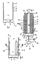
- Fig. 1 is an intermediate stage during the manufacturing process of a two-chamber pressure pack one of an outer container 1 and an inner container 2 existing two-chamber pressure pack unit 3 shown in longitudinal section.
- the outer container 1 is formed by an aluminum can which is attached to an intended Usually use bottom end with one after inside curved bottom 4 is provided.
- a bottom hole centrally 5 drilled as a passage opening for the later introduction of propellant.
- the upper end is normally the outer container 1 and the inner container 2 used therein are still completely open and thus provided with a large opening 6. At the edge of the opening is the outer container 1 expanded to the outside.
- the inner container 2 is like the outer container 1 rotationally symmetrical and in the Outer container 1 inserted.
- the inner container 2 is made of a bag annealed aluminum. The strength and consistency of the aluminum wall is such that it is similar to e.g. a metal toothpaste tube though has a certain stiffness, but is otherwise easily deformable is.
- the inner container defines in its interior a product chamber 7 for product, being in the space between the inner container 2 and the outer container 1 a propellant chamber 8 is formed.
- the two-chamber pressure pack unit 3 is provided with a connecting area 9. In this connection area 9, the inner container 2 is expanded and with the outer container 1 firmly and sealed connected.
- the present Embodiment happens the connection between the outer container 1 and inner container 2 in the connection area 9 by gluing the containers 1, 2.
- FIG WO 99/20413 How such a two-chamber pressure pack unit 3 can be produced is shown in FIG WO 99/20413, to which express reference is made for further details.
- 2 is a further processing step for processing the Two-chamber pressure pack unit 3 by means of a processing device 10 clarifies.
- the processing device 10 has one in the two-chamber pressure pack unit 3, more precisely in the one in the outer container 1
- Inner container 2 insertable tool dome 11 and a pressurization device 12 for generating a pressure difference between the inside and exterior of the inner container 2, i.e. between the filling chamber 7 and the Propellant chamber 8 on.
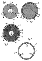
- FIGS. 2 and 4 to 7 are three indentations distributed over the circumference of the tool dome 11 14 provided.
- the indentations 14 extend from the Tip 15 of the tool dome 11 in the axial direction at least over a part of the area of the to be introduced into the two-chamber pressure pack unit Tool dome 11.
- the tool dome 11 is also part of the pressurizing device 12 provided with an inner cavity 16, which in the example shown is formed by a longitudinal center hole.
- the inner cavity 16 is from outside that to be introduced into the two-chamber pressure pack unit 3 Area accessible through an opening 17.
- With the indentations 14 is the inner cavity 16 through at least one fluid channel 18, in the illustrated Example four fluid channels 18 per indentation 14, in fluid communication.
- the fluid channels 18 extend in the radial direction from the inner cavity 16 to for each indentation 14.
- the pressurizing device 12 further a device 19 for generating a pressure differential surge on.
- the device 19 is for generating a pressure differential surge by a device for applying pressure of the inner container 2 through the bottom hole 5 with a blast of compressed air
- the device 20 for loading the inner bag through the bottom hole has a pump device 21 for generating an excess pressure, a valve device 22 and a connection 23 for the bottom hole 5.
- a Controller 24 are the strength and pressurization time of the Air pressure adjustable.
- FIG. 3 is a longitudinal section comparable to that of FIG. 1 of the two-chamber pressure pack unit 3 with formed Inner container 2 shows.
- the inner container 2 are accordingly Number of indentations 14 on the tool mandrel 11 several flattenings or indentations 25 introduced
- the effect of these flattening or indentations 25 is that the inner container 9 in the intended use later Use of the two-chamber pressure pack under the influence of pressure due to the propellant when crumpling exactly at these flattenings or indentations 25 bends inwards. Due to the regular structure of the flats or indentations 25 is thus the formation of sharp folds or edges on the inner container 2 avoided.
- the result is complete Emptying the inner container 2 possible, the proportion of leakages of the inner container 2 in the course of use of the two-chamber pressure pack is significantly reduced.
- the flats or indentations 25 of the inner container thus form target deformation zones, a deformation of the inner container when the Specify contents in a very defined form.
- FIG. 4 which shows a cross section of the tool dome 11
- Fig. 5 shows a cross section along the line V-V of Fig. 2 and shows the two-chamber pressure pack unit 3 with still unshaped Inner container 2 before the pressure surge.
- Fig. 6 shows one another section with a further embodiment of a tool dome 11 ', after the pressure shock has occurred. This clearly shows how the inner container 2 adapts to the contour of the tool dome 11 '.
- a two-chamber pressure pack is then by pulling in the intended Use top end 26, which with the connecting area 9th is provided, to a conically tapering mouthpiece, the one shown in FIG. finished two-chamber pressure pack 27 for delivery to the bottler manufactured.
- the conically tapering mouthpiece 28 is clearly closed see that with a narrowed compared to the large opening 6 discharge opening 29 is provided.
- the discharge opening 29 or better filling opening for the filling material - is bordered by a border 30, which is by common bordering of the outer container 1 and the one with the flats or indentations 25 provided inner container 2 is formed.
- the Dispensing opening 29 introduced the filling material and the dispensing opening 29 by means of a valve cover (not shown) closed in a known manner.
- the propellant is introduced, whereupon also the bottom hole 5 is closed.
- 9 to 11 are still further embodiments of the device 10 for processing the inner container 2 and / or two-chamber pressure pack manufacturing devices 31 for producing a two-chamber pressure pack 27 or a two-chamber pressure pack unit 3 shown.
- Fig. 9 shows a longitudinal section through an essential part of such Two-chamber pressure pack manufacturing device 31.
- the two-chamber pressure pack manufacturing device 31 has an expansion dome 32, which is similar to that is known from WO 99/20413 expanded dome.
- the expanding mandrel 32 shown here also has an elastic one Element 33 with which the inner container 2 to create the connection area 9 are pressed onto the outer container 2 by widening can.
- the expanding mandrel 32 shown differs from the known ones Expanding mandrel in that the tip 15 of the same as tool mandrel 34 for Introducing target deformation zones (indentations 25) into the inner container 2 is formed.
- Fig. 10 is a cross section 9 along the line X-X of FIG. 9 through the tool mandrel 34. Similar to the tool dome 11, 11 'also has the tool dome 34 on the circumference distributed indentations 14 on the channels 18 with the inner cavity 16 are in fluid connection in the tool dome 34. Longitudinally through the entire Expanding dome 32 is a longitudinal fluid channel 35 as part of the pressurization device 12 formed
- This pressurizing device 12 has in the embodiment shown in Fig. 9 as a device for generation a differential pressure surge 19 to the connection opening 17 of the fluid channel system 35, 16, 18 connected device 36 for applying a vacuum on.
- This has next to the pump device 21, which here in reverse Direction as operated in the device 20, also the valve filing 22nd and the control device 14.
- the volume is formed by forming the indentations 25 to a greater or lesser extent the filling chamber 7 adjustable. This is done by selecting the number and the volume of the indentations 14 on the tool dome 11, 11 ', 34.
- Figure 11 shows a set of interchangeable tool domes 34a, 34b, 34c for this purpose instead of the tool dome 34 on the two-chamber pressure pack manufacturing device 31 can be used.
- the tool domes 34a, 34b, 34c have more or less deep and / or more or less long indentations 14a, 14b, 14c.
Landscapes
- Engineering & Computer Science (AREA)
- Mechanical Engineering (AREA)
- Chemical & Material Sciences (AREA)
- Dispersion Chemistry (AREA)
- Physics & Mathematics (AREA)
- Fluid Mechanics (AREA)
- Containers And Packaging Bodies Having A Special Means To Remove Contents (AREA)
- Nozzles (AREA)
Abstract
Description
- Fig. 1
- eine noch nicht zum Ausbilden eines Mundstücks umgeformte, aus einem Außenbehälter und einem darin eingeführten Innenbehälter bestehende Zweikammerdruckpackungseinheit;
- Fig. 2
- einen Längschnhtt durch die Zweikammerdruckpackungseinheit von Fig. 1, wobei ein Werkzeugdom einer Bearbeitungsvorrichtung zum Bearbeiten des Innenbehälters darin eingeführt ist;
- Fig. 3
- einen Längsschnitt durch die Zweikammerdruckpackungseinheit nach Bearbeitung mit dem Bearbeitungswerkzeug, wobei Sollverformungszonen eingebracht sind;
- Fig. 4
- eine Querschnittsansicht durch den Werkzeugdom nach Fig. 2;
- Fig. 5
- eine Querschnittsansicht entlang der Linie V-V von Fig. 2 durch den Werkzeugdom und die darüber befindliche Zweikammerdruckpackungseinheit;
- Fig. 6
- eine Querschnittsansicht vergleichbar der von Fig. 5 durch einen Werkzeugdom in einer zweiten Ausführungsform mit darübergestülpter Zweikammerdruckpackungseinheit, wobei bereits Sollverformungszonen in den Innenbehälter eingebracht worden sind;
- Fig. 7
- eine Querschnittsansicht durch die Zweikammerdruckpackungseinheit nach Fig. 6 bzw. Fig. 3 ohne Werkzeugdom;
- Fig. 8
- einen Längeschnitt durch eine fertige Zweikammerdruckpackung mit einem Innenbeutel mit Sollverformungszonen, und einen konisch verjüngten Mundstück;
- Fig. 9
- einen Längsschnitt durch eine Vorrichtung zur Herstellung einer Zweikammerdruckpackung mit aufgeschobener Zweikammerdruckpackungseinheit während eines Aufweitvorganges;
- Fig. 10
- einen Schnitt entlang der Linie X-X von Fig. 9 durch einen Endbereich eines Werkzeugdoms der Vorrichtung; und
- Fig. 11
- drei Halbquerschnitte entlang der Linie XI-XI von Fig. 10, die jeweils verschiedene Ausführungsformen von Werkzeugdomen zeigen.
Claims (26)
- Verfahren zum Herstellen einer Zweikammerdruckpackung (27) mit einem Außenbehälter (1),einem im Außenbehalter (1) befindlichen, bleibend deformier- oder verknautschbaren Innenbehälter (2), wobei im Innenbehälter (2) eine Füllgutkammer (7) für Füllgut und zwischen dem Innenbehälter (2) und dem Außenbehälter (1) eine davon fluiddicht abgetrennte Treibmittelkammer (8) zur Aufnahme eines Treibmittels gebildet ist,einem sich konisch verengenden, eine zur Füllgutkammer führende Abgabeöffnung (29), die mittels eines ein Sprühventil oder dergleichen aufweisenden Deckels verschileßbar ist, aufweisenden Mundstück (28) und einer in die Treibmittelkammer (8) führenden Durchgangsöffnung (5) zum Einbringen des Treibmittels,umfassend die folgende Reihenfolge von Schritten:gekennzeichnet durchBereitstellen eines Außenbehälterrohlings (1) mit noch ungeformten Mundstück mit einer großen Öffnung (6) darin,Einbringen des Innenbehälters (2) durch die große Öffnung (6) des noch ungeformten Mundstücks,Umformen des Mundstück (28) unter Verengen der großen Öffnung (6) zum Bilden der Abgabeöffnung (29),Versehen des Innenbehälters (2) nach dessen Einbringen in den Außenbehälter (1) mit Sollverformungszonen - wie Abflachungen, Einbuchtungen (25), Faltzonen oder dergleichen -, die für eine gezielte Deformation oder Verknautschung des Innenbehälters (2) in der gebrauchsfertigen Zweikammerdruckpackung (27) bei Abgabe des Füllgutes sorgen.
- Verfahren nach Anspruch 1,
dadurch gekennzeichnet,daß der Innenbehälter (2) zum Ausbilden der Sollverformungszonen (25) nach seinem Einbringen innerhalb des Außenbehälters (1) umgeformt wird. - Verfahren nach einem der Ansprüche 1 oder 2,
gekennzeichnet durchvor, während oder nach dem Ausbilden der Sollverformungszonen (25) erfolgendes Andrücken des in den Außenbehälter (1) eingebrachten Innenbehälters (2) an den Außenbehälter (1) im Bereich der großen Öffnung (6), um Innen- und Außenbehälter (2; 1) mittels Verkleben, Verschweißen und/oder Umformen, insbesondere gemeinsames Umlegen oder Umbördein, oder dergleichen vorzugsweise dichtend miteinander zu verbinden (Verbindungsbereich 9). - Verfahren nach Anspruch 2 oder nach Anspruch 2 und Anspruch 3,
dadurch gekennzeichnet,daß das Umformen des Innenbehälters (2) zum Ausbilden der Sollverformungszonen (25) mittels Einführen eines Werkzeugdorns (11, 11', 32/34, 34, 34a, 34b, 34c), der zumindest bereichsweise mit einer der gewünschten Sollverformungszonenausbildung entsprechenden Kontur (14, 14a, 14b, 14c) versehen ist, und Sog- und/oder Druckbeaufschlagung des Innenbehälters (2) in der Art, daß er sich an den Werkzeugdom (11, 11', 32/34, 34, 34a, 34b, 34c) anlegend entsprechend dessen Kontur umformt, erfolgt. - Verfahren nach Anspruch 4,
dadurch gekennzeichnet,daß für die Sogbeaufschlagung ein Vakuum an wenigstens einem in und/oder am Werkzeugdom (11, 32/34, 34, 34a, 34b, 34c) verlaufenden Fluidkanal (16/17/18, 16/35/17/18) angelegt wird, wodurch der Innenbehälter (2) an den Werkzeugdom (11, 32/34, 34, 34, 34b, 34c) angesogen wird. - Verfahren nach Anspruch 4 oder Anspruch 5,
wobei der Innenbehälter (2) und der Außenbehälter (1) vor dem Ausbilden der Sollverformungszonen (25) abdichtend miteinander verbunden sind (Verbindungsbereich 9),
dadurch gekennzeichnet,daß die Druckbeaufschlagung durch das zur Treibmittelkammer (8) führende Durchgangsloch (5), insbesondere mittels eines kurzen Luftstoßes von 0,2-1s Länge mit 1 bist 3 bar, verfolgt. - Verfahren nach einem der Ansprüche 4 bis 6,
dadurch gekennzeichnet,daß ein Werkzeugdom (11, 11', 32/34, 34, 34a, 34b, 34c) verwendet wird, dessen freier Endbereich (15) am Außenumfang mit längs der Dornachse sich vom freien Ende (15) bis zu einem einer Teilhöhe des Innenbehälters (2) entsprechenden Bereichs verlaufenden Einbuchtungen (14, 14a, 14b, 14c) versehen ist, an die sich der Innenbehälter (2) bei der Sog- oder Druckbeaufschlagung die Sollverfomungszonen bildende Abflachungen oder Einbuchtungen (25) ausbildend anlegt. - Verfahren nach einem der Ansprüche 1 bis 7,
dadurch gekennzeichnet,daß über Ausbilden der Sollverformungszonen (25) das Innenvolumen des Innenbehälters (2) gezielt eingestellt wird. - Verfahren nach Anspruch 8 und einem der Ansprüche 4 bis 7,
dadurch gekennzeichnet,daß zum Einstellen des gewünschten Volumens die Sog- oder Druckbeaufschlagung verwendet wird und/oder ein entsprechend größere oder kleinere und/oder mehr oder wenigem Einbuchtungen (14, 14a, 14b, 14c), aufweisender Werkzeugdom (11, 11', 32/34, 34, 34a, 34b, 34c) verwendet wird. - Verfahren nach einem der Ansprüche 4 bis 9,
dadurch gekennzeichnet,daß als Werkzeugdom (32/34) ein Einführ- und/oder Aufweitdom (32) zum Einführen und/oder Andrücken des Innenbehälters (2) in den bzw. an den Außenbehälter (1) verwendet wird. - Verfahren nach Anspruch 3 und Anspruch 10,
dadurch gekennzeichnet,daß das Andrücken des Innenbehälters (2) an den Außenbehälter (1) und das Ausbilden der Sollverformungszonen (25) gleichzeitig oder das Ausbilden unmittelbar nach dem Andrücken erfolgt. - Zweikammerdruckpackung mit:wobei der Innenbehälter sich der Innenkontur des zum Mundstück (28) verjüngten Außenbehälters (1) anfügend und/oder angepaßt gemeinsam mit dem Außenbehälter (1) umbördelt (30) oder um die die Abgabeöffnung (29) in dem verjüngten Mundstück (28) begrenzende Umbördelung (30) des Außenbehälters (1) herumgelegt ist,einem rotationssymetrischen Außenbehälter (1) mit einer zylindermantelförmigen Umfangswandung,einem im Außenbehälter befindlichen, bleibend deformier- oder verknautschbaren Innenbehälter (2), der in seinem Innern eine Füllgutkammer (7) für Füllgut und zwischen sich und dem Außenbehälter (1) eine davon fluiddicht abgetrennte Treibmittelkammer (8) zur Aufnahme von Treibmittel definiert,einem in dem Außenbehälter (1) angebrachten, in die Treibmittelkammer (8) mündenden Durchgangsloch - insbesondere Bodenloch (5) - zum Einbringen des Treibmittels,einem sich konisch von der zylindermantelförmigen Umfangswandung aus zum Abgabeende (26) verjüngenden Mundstück (28) mit einer umbördelten vorzugsweise kreisförmigen Abgabeöffnung (26) an diesem verjüngten Abgabeende (26), welche Abgabeöffnung (29) mit einem ein Sprühventil oder dergleichen aufweisenden Deckel fest verschließbar ist,
dadurch gekennzeichnet,daß der Innenbehälter (2), insbesondere an dem der Abgabeöffnung (29) abgewandten Endbereich seiner Umfangswandung, mit wenigstens einer Sollverformungszone (25) versehen ist, durch die er sich definiert bei Abgabe des Füllguts sein Innenvolumen verringernd deformiert bzw. verknautscht. - Zweikammerdruckpackung nach Anspruch 12,
gekennzeichnet durchmehrere sich axial erstreckende, am Umfang des Innenbehälters (2) verteilte Sollverformungszonen (25). - Zweikammerdruckpackung nach Anspruch 12 oder 13,
dadurch gekennzeichnet,daß die wenigstens eine Sollverformungszone oder jede von mehreren solcher Sollverformungszonen durch eine Abflachung oder Einbuchtung (25) an dem ansonsten zylindermantelförmig ausgebildeten Umfangswandbereich des Innenbehälters (2) ausgebildet ist. - Zweikammerdruckpackung nach Anspruch 14,
dadurch gekennzeichnet,daß die Abflachung oder Einbuchtung (25) sich von dem dem Abgabeende (29) abgewandten Ende in axialer Richtung teilbereichsweise über den zylindermantelförmigen Umfangswandbereich des Innenbehälters (2) erstreckt. - Zweikammerdruckpackung nach einem der Ansprüche 12 bis 15,
dadurch gekennzeichnet,daß der Innenbehälter (2) aus Aluminium, insbesondere weichgeglühtem Aluminium besteht oder gebildet ist. - Bearbeitungsvorrichtung zum Bearbeiten eines in einem Außenbehälter (1) eingesetzten Innenbehälters (2) im Zuge der Herstellung einer Zweikammerdruckpackung (27),
gekennzeichnet durcheinen Werkzeugdom (11, 11', 32/34, 34, 34a, 34b, 34c) zum Eingeführt-werden in den Innenbehälter (2), wobei der Werkzeugdom (11, 11', 32/34, 34, 34a, 34b, 34c) zum Ausbilden von Sollverformungszonen (25) an dem Innenbehälter (2) an seiner Umfangsfläche mit wenigstens einer Ausbuchtung oder bevorzugt Einbuchtung (14, 14a, 14b, 14c) versehen ist, undeine Druckbeaufschlagungseinrichtung (12) zum Beaufschlagen des Innenbehälters (2), der über den Werkzeugdom (11, 11', 32/34, 34, 34a, 34b, 34c) geschobenen, aus dem Außenbehälter (1) und dem darin befindlichen Innenbehälter (2) bestehenden Zweikammerdruckpackungseinheit (3) mit unterschiedlichem Innen- und Außendruck in der Art, daß der Innenbehälter auf den Werkzeugdorn gesogen oder gepreßt wird. - Bearbeitungsvorrichtung nach Anspruch 17,
dadurch gekennzeichnet,daß der Werkzeugdom (11, 11', 32/34, 34, 34a, 34b, 34c) mit wenigstens einer, vorzugsweise mehreren, insbesondere über den Umfang verteilten, Einbuchtungen (14) versehen ist, die von der Spitze (15) bzw. dem Einführende ausgehend sich in axialer Richtung über einen Teilbereich erstreckt bzw. erstrecken. - Bearbeitungsvorrichtung nach einem der Ansprüche 17 oder 18,
dadurch gekennzeichnet,daß die Umfangsfläche des Werkzeugdoms (11, 11', 32/34, 34, 34a, 34b, 34c) in einem zum Einführen in den Innenbeutel (2) bestimmten Bereich außerhalb der Einbuchtungen im wesentlichen zylindermantelförmig ausgebildet ist. - Bearbeitungsvorrichtung nach einem der Ansprüche 17 bis 19,
dadurch gekennzeichnet,daß der Werkzeugdom (11, 32/34, 34, 34a, 34b, 34c) einen inneren Hohlraum, insbesondere eine axiale Längsbohrung (16), aufweist, wobei der innere Hohlraum (16) mit einer Öffnung (17) an einem nicht zum Einführen in die Zweikammerdruckpackungseinheit (3) bestimmten Bereich des Werkzeugdorns (11, 32/34, 34, 34a, 34b, 34c) in Fluidverbindung ist. - Bearbeitungsvorrichtung nach Anspruch 20,
dadurch gekennzeichnet,daß wenigstens ein Fluidkanal (18) zwischen dem inneren Hohlraum (16) und Jeder Einbuchtung (14) am Werkzeugdom (11, 32/34, 34, 34a, 34b, 34c) vorgesehen ist. - Bearbeitungsvorrichtung nach einem der Ansprüche 17 bis 21,
dadurch gekennzeichnet,daß die Druckbeaufschlagungseinrichtung (12, 19) eine Einrichtung (20) zum Beaufschlagen des Innenbehälters (2) durch das Durchgangsloch (5),das zum Einbringen des Treibmittels im Außenbehälter (1) vorgesehen ist,mit einem Druckfluidstoß, insbesondere einem Druckluftstoß, und/oder eine Einrichtung (36) zum Evakuieren des Innenraums (7) des Innenbehälters (2) durch ein Fluidkanalsystem (14, 18, 16, 17; 14, 18, 16, 35, 17) im oder am Werkzeugdorn (11, 32/34, 34, 34a, 34b, 34c) aufweist. - Bearbeitungsvorrichtung nach Anspruch 22 und Anspruch 21,
dadurch gekennzeichnet,daß die Einrichtung (36) zum Evakuieren des Innenraums (7) eine mit dem inneren Hohlraum (16) oder der Längsbohrung des Werkzeugdoms (11, 32/34, 34, 34a, 34b, 34c) in Fluidverbindung bringbare Pumpeneinrichtung (21) umfaßt. - Bearbeitungsvorrichtung nach einem der Ansprüche 17 oder 22,
dadurch gekennzeichnet,daß der Werkzeugdorn (11, 11', 32/34, 34, 34a, 34b, 34c) aus oder mit Metall, insbesondere Stahl, und/oder Kunststoff gebildet ist. - Zweikammerdruckpackungsherstellvorrichtung zur Durchführung des Verfahrens nach einem der Ansprüche 1 bis 11 oder zur Herstellung einer Zweikammerdruckpackung nach einem der Ansprüche 12 bis 16,
gekennzeichnet durcheine Bearbeitungsvorrichtung (10, 32/34) nach einem der Ansprüche 17 bis 24. - Zweikammerdruckpackungsherstellvorrichtung nach Anspruch 25,
gekennzeichnet durcheinen Aufnahmedorn oder Aufweitdorn (32) mit einem elastischem Körper (33) als Aufweitwerkzeug zum Aufweiten und Andrücken des Innenbehälters (2) an den Außenbehälter (1), um die Behälter (1, 2) dichtend im Bereich (9) ihrer Abgabeöffnungen (6, 29) miteinander zu verbinden,
wobei der Aufnahmedorn bzw. Aufweitdorn (32) gleichzeitig als Werkzeugdom (32/34) der Bearbeitungsvorrichtung nach einem der Ansprüche 17 bis 24 ausgebildet ist.
Applications Claiming Priority (4)
| Application Number | Priority Date | Filing Date | Title |
|---|---|---|---|
| DE19926496 | 1999-06-10 | ||
| DE19926496 | 1999-06-10 | ||
| DE19932680A DE19932680C2 (de) | 1999-06-10 | 1999-07-13 | Verfahren und Vorrichtung zur Herstellung einer Zweikammerdruckpackung |
| DE19932680 | 1999-07-13 |
Publications (2)
| Publication Number | Publication Date |
|---|---|
| EP1059129A2 true EP1059129A2 (de) | 2000-12-13 |
| EP1059129A3 EP1059129A3 (de) | 2001-09-26 |
Family
ID=26053725
Family Applications (1)
| Application Number | Title | Priority Date | Filing Date |
|---|---|---|---|
| EP00110460A Withdrawn EP1059129A3 (de) | 1999-06-10 | 2000-05-16 | Verfahren und Vorrichtung zur Herstellung einer Zweikammerdruckpackung, Bearbeitungswerkzeug zur Verwendung darin sowie damit herstellbare Zweikammerdruckpackung |
Country Status (1)
| Country | Link |
|---|---|
| EP (1) | EP1059129A3 (de) |
Family Cites Families (3)
| Publication number | Priority date | Publication date | Assignee | Title |
|---|---|---|---|---|
| DE2103447B1 (de) * | 1971-01-26 | 1972-08-17 | Presspack Co., Schaffhausen (Schweiz) | Dose zur Aufnahme und Abgabe von flüssigen Massen unter Druck |
| US3979025A (en) * | 1975-07-24 | 1976-09-07 | Richard Friedrich | Devices for holding and discharging liquid and paste-like substances under pressure |
| DE3802314C1 (de) * | 1988-01-27 | 1989-10-26 | Stoffel, Gerd, 7750 Konstanz, De |
-
2000
- 2000-05-16 EP EP00110460A patent/EP1059129A3/de not_active Withdrawn
Also Published As
| Publication number | Publication date |
|---|---|
| EP1059129A3 (de) | 2001-09-26 |
Similar Documents
| Publication | Publication Date | Title |
|---|---|---|
| DE3802314C1 (de) | ||
| DE69802712T2 (de) | Ein durch innenhochdruck umgeformten bauteil, sowie verfahren und vorrichtung zur dessen herstellung | |
| DE60201504T2 (de) | Verfahren und vorrichtung zum einhalsen der öffnung eines behälters | |
| DE2353209A1 (de) | Tiefgezogener behaelter und verfahren zu seiner herstellung | |
| DE3423900C2 (de) | ||
| EP2426080B1 (de) | Verfahren zur Herstellung eines Trichters, Trichter und Behälter mit Trichter | |
| DE1561546B1 (de) | Behaelter mit einem Aufnahmeteil und einem Stuetzteil sowie Verfahren zu dessen Herstellung und Werkzeug zur Durchfuehrung des Verfahrens | |
| DE2130426A1 (de) | Verfahren und Vorrichtung zum Ziehen von Bechern aus Blech | |
| DE69200315T3 (de) | Vorrichtung und Verfahren zum Wieder-im-Form-bringen von Behältern. | |
| EP1027268B1 (de) | Verfahren zur herstellung einer zweikammerdruckpackung und vorrichtung zur durchführung des verfahrens | |
| DE7029199U (de) | Behaelter mit falzverbindung | |
| DE2328363C3 (de) | Rollrand an einem Druckbehälter sowie Verfahren und Werkzeug zu seiner Herstellung | |
| EP2804706B1 (de) | Verfahren zur herstellung einer dose mit einem aufreissdeckel sowie dose mit einem aufreissdeckel | |
| DE60023051T2 (de) | Vorrichtung zum Herstellen einer auswärts gebördelten Lippe auf einem zylindrischen Behälterkörper | |
| DE4413331B4 (de) | Verfahren zum Herstellen einer Zweikammer-Druckpackung | |
| DE4428435A1 (de) | Verfahren zum Herstellen eines luftspaltisolierten Rohres | |
| EP1654080A1 (de) | Verfahren zum innenhochdruckumformen von konischen rohren aus metall | |
| DE19932680C2 (de) | Verfahren und Vorrichtung zur Herstellung einer Zweikammerdruckpackung | |
| DE69635381T2 (de) | Abgedichteter Montageteller für Aerosolbehälter | |
| EP1732824B1 (de) | Schlauchbeutel mit einem schlauchbeutelkörper und einem eingesiegelten boden | |
| EP1059129A2 (de) | Verfahren und Vorrichtung zur Herstellung einer Zweikammerdruckpackung, Bearbeitungswerkzeug zur Verwendung darin sowie damit herstellbare Zweikammerdruckpackung | |
| EP0639509A1 (de) | Tiefgezogener Behälterdeckel aus Papier und Verfahren zu seiner Herstellung | |
| DE69903516T2 (de) | Verfahren zum herstellen eines metallbehalters mit einem einsatzstück zum verpacken ,zum beispiel, ein nahrungsmittel, und so ein behalter | |
| EP1030752A1 (de) | Verfahren und vorrichtung zur herstellung eines integralgehäuses für hydrolenkung | |
| EP1497108B1 (de) | Dose mit faltlinien und verfahren zu ihrer herstellung |
Legal Events
| Date | Code | Title | Description |
|---|---|---|---|
| PUAI | Public reference made under article 153(3) epc to a published international application that has entered the european phase |
Free format text: ORIGINAL CODE: 0009012 |
|
| AK | Designated contracting states |
Kind code of ref document: A2 Designated state(s): AT BE CH CY DE DK ES FI FR GB GR IE IT LI LU MC NL PT SE |
|
| AX | Request for extension of the european patent |
Free format text: AL;LT;LV;MK;RO;SI |
|
| PUAL | Search report despatched |
Free format text: ORIGINAL CODE: 0009013 |
|
| AK | Designated contracting states |
Kind code of ref document: A3 Designated state(s): AT BE CH CY DE DK ES FI FR GB GR IE IT LI LU MC NL PT SE |
|
| AX | Request for extension of the european patent |
Free format text: AL;LT;LV;MK;RO;SI |
|
| 17P | Request for examination filed |
Effective date: 20011207 |
|
| 17Q | First examination report despatched |
Effective date: 20020327 |
|
| AKX | Designation fees paid |
Free format text: AT BE CH CY DE DK ES FI FR GB GR IE IT LI LU MC NL PT SE |
|
| RTI1 | Title (correction) |
Free format text: METHOD AND DEVICE FOR PRODUCING A TWO CHAMBER PRESSURE PACK AND FORMING TOOL USED THEREIN |
|
| GRAH | Despatch of communication of intention to grant a patent |
Free format text: ORIGINAL CODE: EPIDOS IGRA |
|
| STAA | Information on the status of an ep patent application or granted ep patent |
Free format text: STATUS: THE APPLICATION IS DEEMED TO BE WITHDRAWN |
|
| 18D | Application deemed to be withdrawn |
Effective date: 20030122 |
|
| REG | Reference to a national code |
Ref country code: HK Ref legal event code: WD Ref document number: 1038528 Country of ref document: HK |