EP1059140A2 - Handarbeitsgerät - Google Patents
Handarbeitsgerät Download PDFInfo
- Publication number
- EP1059140A2 EP1059140A2 EP00110771A EP00110771A EP1059140A2 EP 1059140 A2 EP1059140 A2 EP 1059140A2 EP 00110771 A EP00110771 A EP 00110771A EP 00110771 A EP00110771 A EP 00110771A EP 1059140 A2 EP1059140 A2 EP 1059140A2
- Authority
- EP
- European Patent Office
- Prior art keywords
- housing
- hand tool
- tool according
- hand
- milling disk
- Prior art date
- Legal status (The legal status is an assumption and is not a legal conclusion. Google has not performed a legal analysis and makes no representation as to the accuracy of the status listed.)
- Granted
Links
Images


Classifications
-
- B—PERFORMING OPERATIONS; TRANSPORTING
- B28—WORKING CEMENT, CLAY, OR STONE
- B28D—WORKING STONE OR STONE-LIKE MATERIALS
- B28D1/00—Working stone or stone-like materials, e.g. brick, concrete or glass, not provided for elsewhere; Machines, devices, tools therefor
- B28D1/18—Working stone or stone-like materials, e.g. brick, concrete or glass, not provided for elsewhere; Machines, devices, tools therefor by milling, e.g. channelling by means of milling tools
- B28D1/183—Hand tools, e.g. portable, motor driven
-
- B—PERFORMING OPERATIONS; TRANSPORTING
- B27—WORKING OR PRESERVING WOOD OR SIMILAR MATERIAL; NAILING OR STAPLING MACHINES IN GENERAL
- B27B—SAWS FOR WOOD OR SIMILAR MATERIAL; COMPONENTS OR ACCESSORIES THEREFOR
- B27B5/00—Sawing machines working with circular or cylindrical saw blades; Components or equipment therefor
- B27B5/02—Sawing machines working with circular or cylindrical saw blades; Components or equipment therefor characterised by a special purpose only
- B27B5/08—Sawing machines working with circular or cylindrical saw blades; Components or equipment therefor characterised by a special purpose only for sawing with the saw blade abutting parallel against a surface of the workpiece
-
- B—PERFORMING OPERATIONS; TRANSPORTING
- B27—WORKING OR PRESERVING WOOD OR SIMILAR MATERIAL; NAILING OR STAPLING MACHINES IN GENERAL
- B27B—SAWS FOR WOOD OR SIMILAR MATERIAL; COMPONENTS OR ACCESSORIES THEREFOR
- B27B5/00—Sawing machines working with circular or cylindrical saw blades; Components or equipment therefor
- B27B5/29—Details; Component parts; Accessories
- B27B5/30—Details; Component parts; Accessories for mounting or securing saw blades or saw spindles
- B27B5/32—Devices for securing circular saw blades to the saw spindle
-
- B—PERFORMING OPERATIONS; TRANSPORTING
- B28—WORKING CEMENT, CLAY, OR STONE
- B28D—WORKING STONE OR STONE-LIKE MATERIALS
- B28D1/00—Working stone or stone-like materials, e.g. brick, concrete or glass, not provided for elsewhere; Machines, devices, tools therefor
- B28D1/02—Working stone or stone-like materials, e.g. brick, concrete or glass, not provided for elsewhere; Machines, devices, tools therefor by sawing
- B28D1/04—Working stone or stone-like materials, e.g. brick, concrete or glass, not provided for elsewhere; Machines, devices, tools therefor by sawing with circular or cylindrical saw-blades or saw-discs
- B28D1/045—Sawing grooves in walls; sawing stones from rocks; sawing machines movable on the stones to be cut
Definitions
- the invention relates to a hand tool, in particular for Cutting a metal clip in a masonry, with a milling disc or Like. That over a drive flange with a drive motor of the hand tool is driven.
- the window frames In the case of old building renovations in particular, the window frames must be removed from the masonry for renovation purposes, so that the metal clips locking the window frames must be severed.
- hand tools of the aforementioned type are usually used, by means of which grooves are milled into the masonry in order to release the metal clips.
- the penetration of the milling disk into the masonry causes a great deal of contamination because the mortar dust is thrown into the environment in an uncontrolled manner by the rotation of the milling disk.
- a hand saw with a suction device is known from EP 0 579 964 A1, by means of which the accumulated dust is taken up and passed into a collection container becomes.
- a disadvantage of this prior art has been found to be that moving tool lies open on the workpiece to be machined, so that due to the linear movement of the tool, the resulting dust from the intake duct is flung away; thus only a certain proportion of the dust can be vacuumed up.
- the known hand saw is not suitable for work on loosening window frames can be used because it performs a linear movement; the hand tool for However, loosening window frames from masonry involves a rotational movement should perform, since only by means of a rotational movement a uniform linear Guidance of the hand tool along the window frame is guaranteed.
- a hand tool is known, the one in one Has housing of the hand tool mounted milling disc.
- the milling disc emerges from an end face of the housing.
- the Hand tool is used to create grooves in which connectors with two adjacent circular sections are to be included.
- the hand tool of the aforementioned Genus in such a way that it is possible to window frames from the Loosen masonry without the dirt that accumulates in the environment reached.
- the hand tool should also be handy and easy to use, so that the work can be carried out reliably and quickly. Furthermore, an adaptation to different distances between the starting glass pane and the window or door frame should be possible by means of the hand-held tool according to the invention, so that the hand-held tool can be guided thereon regardless of the distance of the groove from the window and door frame.
- the milling disc in one attached to the handheld device housing, in which the metal clips facing end face an outlet opening is provided for the milling disk, or that the milling disk in the area of the outlet opening, at least partially, from the Housing protrudes, and that on the housing, preferably the outlet opening opposite, an outlet channel is provided.
- the outer wall of the housing opposite the drive flange is designed as a guide member in the region of the outlet opening of the milling disk.
- a contact web is attached, which has a contact surface running perpendicular to the outlet opening.
- a contact plate For variable adjustment of the distance between a lower plate of the Housing in relation to the contact surface of the window or door frame is on the Housing of the handheld device attached a contact plate, by means of which Distance between the contact plate and the milling disc is adjustable.
- the contact plate is permanently on the side of the window or door frame, so that the hand tool during the axial movement to sever the Metal clips held in the masonry on the window or door frame is.
- the height adjustment of the contact plate is accomplished by turning it on two threaded spindles mounted in the housing is held and that the two Threaded spindles with each other in a form-fitting manner by means of a connecting pin Active connection.
- one of the two threaded spindles an adjustment screw protruding from the housing for height adjustment of the Support plate provided, which is mounted in the housing of the hand tool.
- the outer wall of the housing is centrally countersunk in the milling disc incorporated.
- one is centered in the drive flange Threaded hole arranged and the milling disc is by means of a Countersunk screw provided with external thread and engaging in the threaded bore attached to the drive flange.
- the milling cutter attached to the hand tool has a two-part housing, wherein the first housing part is firmly connected to the hand tool and the second housing part is adjustable relative to the first housing part.
- the subject of the invention advantageously enables that commercially available hand tools, such as a flex or milling machine, can be used to loosen metal clips plastered into masonry without the mortar being ejected into the environment by the rotation of the milling disk and thus causing unpleasant contamination.
- the part of the milling disk that does not penetrate the masonry is in fact completely enclosed by the housing, so that the mortar or dust is caught by the housing and cannot get into the environment.
- Due to the rotation of the milling disc an air flow occurs within the housing, which takes the mortar in a defined manner in the direction of the outlet channel.
- the outlet channel ends in a collection chamber in which the mortar can be stored until it is emptied.
- the mortar and its dust arrives in a controlled manner in the collecting chamber, so that the metal clips locking the window frame can be cut with the hand-held tool without any appreciable contamination of the surroundings.
- the outer wall of the housing serves as a guide member and the For this purpose, the contact surface forms a right angle, so that the manual tool is precise can be placed between the masonry and the window frame and accordingly a vertical incision in the masonry is done so that along the window frame and as close as possible the metal clip is separated within the masonry, whereby the renovated or new window frame in the original Window recess can be used again without extensive Plastering work or adjustments are necessary.
- the distance between the Glass pane and the window or door frame is of different widths, so that to optimally reinsert the window or door frame into the original window recess can only be achieved if the Cut, i.e. the cutting of the metal clips in the masonry at one exact predetermined place is carried out.
- the lower plate should also of the housing can be guided axially along the window or door frame.
- it is advantageous to provide a contact plate which can be supported on the one hand on the window or door frame and on the other hand, height-adjustable is attached to the housing. With one Contact plate and its concrete height adjustment on the housing of the Hand tool can be the distance between the lower plate of the case and the height of the window frame can be adjusted.
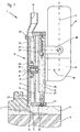
- a hand-held implement 1 is shown, with which one on one Window frames 2 and a house wall 3 attached metal clips 5 are cut should.
- the metal clip 5 namely locks the window frame 2 on the house wall 3 and is covered with a plaster layer 4.
- the hand-held tool 1 has a grip section 6, the longitudinal axis 7 of which, when the hand-held tool 1 is in the working state, points perpendicularly to the house wall 3.
- a milling disk 11 which is fastened to a drive flange 9, is provided on the hand-held tool 1, which are connected to one another by drive and set in rotation by means of a motor 8.
- the longitudinal axis 10 of the drive flange 9 and the longitudinal axis 7 of the hand tool 1 are perpendicular to each other, so that the hand tool 1 can be placed on the window frame 2 by means of pressure.
- the milling disk 11 is in a housing 12, as will be explained in more detail below is arranged, the milling disk 11 thus in the rest position completely encloses.
- a face of the metal clip 5 facing the Housing 12 namely in the extension of the longitudinal axis 7 of the handle portion 6 an outlet opening 15 is machined into the housing 12, through which the milling disk 11 can be passed to penetrate the plaster 4 sufficiently deep and Cut through metal clips 5.
- a collecting chamber not shown, is arranged; This can be a plastic bag, for example, in which the mortar and dust particles are collected in a controlled manner.
- the milling disk 11 has a counterbore 17 in the center through which a countersunk screw 19 provided with an external thread extends.
- a threaded bore 18 is also machined into the center of the drive flange 9, into which the countersunk screw 19 is screwed for fastening the milling disk 11.
- the surfaces of the countersunk screw 19 and the milling disk 11 are thus flat to one another in the assembled state, so that only a small air gap is created between the wall of the housing 12 facing the countersunk screw 19 and the milling disk 11.
- two shear pins 20 are attached to the milling disk 11, which are inserted into holes machined laterally next to the threaded bore 18 of the drive flange 9 in order to drively connect the milling disk 11 to the drive flange 9.
- An abutment web 21 formed on the housing 12 in the region of the outlet opening 15 serves as an abutment surface 22, which can be placed on the surface of the plaster 4. Furthermore, the outer wall of the housing 12 opposite the drive flange 9 is flat, so that this surface can be used as a guide member 23 on the window frame 2 and thus ensures that the hand tool 1 can be moved exactly positioned along the entire window frame 2, since the contact surface 22nd and the guide member 23 are perpendicular to one another and accordingly abut the window frame 2 and the plaster 4 at the same time. The milling disk 11 thus penetrates vertically into the plaster 4, so that a clean, uniform incision is produced.
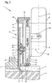
- FIGS. 1 and 2 show the two different positions of the milling disk 11 with respect to the housing 12, namely on the one hand the rest position and on the other hand the working position of the milling disk 11.
- the milling disk 11 In the rest position, the milling disk 11 is located in the housing 12, whereas the working position is characterized in that the milling disk 11 protrudes approximately three to five centimeters from the housing 12. In the working position, it is thus ensured that the milling disk 11 can cut through the metal clips 5 located in the plaster 4.
- the housing 12 in the region of the outlet opening 15 is reduced so that the milling disk 11 in this area with the desired Penetration depth protrudes from the housing 12.
- the housing 12 is formed in two parts, namely the housing 12 consists of a first housing part 13 fixedly attached to the hand-held tool 1 and a second housing part 14 which is adjustable relative to the first housing part 13 and thus also to the milling disk 11.
- the first housing part 13 is fixedly attached to the hand-held tool 1 by means of a holding bracket 28.
- a hole is provided centrally in the housing part 13, through which the drive flange 9 passes and is thus completely enclosed by the housing part 13.
- two guide sections 26 are provided in the housing part 13, each receiving a guide pin 27 which is firmly locked on the second housing part 14. The guide pins 27 accordingly slide in the two guide sections 26 in the adjustment direction of the second housing part 14.
- the springs 29 are arranged, which are subjected to tension when the milling disk 11 is pressed out and thus return the second housing part 14 to the rest position after the work process has ended.
- the springs 29 are attached to the guide pins 27 between the first housing part 13 and the second housing part 14.
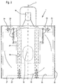
- the springs 29 are arranged laterally next to the housing part 13 and the guide pins 27.
- the mutually facing end faces of the two housing parts 13 and 14 form a stop, so that the freedom of movement of the second housing part 14 is limited.
- the second housing part 14 consists of an upper plate 24 receiving the guide pins and a lower plate 25 which is designed as a guide member 23 in the region of the outlet opening 15.
- the lower plate 25 is fastened to the upper plate 24 by means of two set screws 30. Spacers (not shown) can be used between the two plates 24 and 25 in the area of the adjusting screw 30, so that the distance between the two plates 24 and 25 can be set as desired to accommodate milling discs 11 of different thicknesses.
- the upper plate 24 has one in the area of the drive flange 9 Parting plane on to be able to change the milling disk 11 quickly.
- Both Components of the plate 24 can be detached from one another by means of the guide pins 27 attached, in that in the end faces of the guide pins 27th Threaded holes are machined, into each of which a countersunk screw can be screwed is. In this way, the housing 12 can be almost completely removed from the milling disk 11 can be removed.
- a contact plate 31 is provided, which by means of two Holding leg 32 is locked on the housing 12 adjustable in height.
- the contact plate 31 serves as a guide member 23 abutting the window frame 2 Height adjustment of the contact plate 31 can accordingly the distance between the Milling disc 11 and the window frame 2 can be set reliably without that the intended guidance of the linear movement of the hand tool 1 get lost.
- the holding legs 32 are locked in a sleeve 38 by means of a screw 33.
- Each of the two sleeves 38 has a threaded bore 39 through which a threaded spindle 34, which is rotatably mounted in the housing 12 in bearing bushes 37, projects.
- the two threaded spindles 34 are positively connected on the opposite side of the outlet opening 15 of the milling disk 11 by means of a connecting pin 35.
- an adjusting screw 36 protruding from this is mounted in the housing 12 and cooperates with one of the two threaded spindles 34 in a form-fitting manner.
- the connecting pin 35 is also rotatably supported in the housing 12 by means of two bearing bushes 37.
- the threaded spindles 34 rotate, since they engage with the connecting pin 35 via bevel gears, so that the sleeves 38 arranged thereon are moved synchronously.
- the distance between the contact plate 31 and the milling disk 11 can thus be changed in a simple manner.
Landscapes
- Engineering & Computer Science (AREA)
- Life Sciences & Earth Sciences (AREA)
- Mechanical Engineering (AREA)
- Wood Science & Technology (AREA)
- Forests & Forestry (AREA)
- Mining & Mineral Resources (AREA)
- Milling Processes (AREA)
- Processing Of Stones Or Stones Resemblance Materials (AREA)
- Grinding-Machine Dressing And Accessory Apparatuses (AREA)
Abstract
Description
Dazu werden üblicherweise Handarbeitsgeräte der vorgenannten Art eingesetzt, mittels denen Nuten in das Mauerwerk gefräst werden, um die Metallklipse zu lösen. Das Eindringen der Frässcheibe in das Mauerwerk verursacht hierbei eine große Verschmutzung, da der Mörtelstaub durch die Rotation der Frässcheibe unkontrolliert in die Umgebung geschleudert wird.
Des weiteren soll mittels des erfindungsgemäßen Handarbeitsgerätes eine Anpassung an unterschiedliche Abstände zwischen der beginnenden Glasscheibe und dem Fenster- oder Türrahmen möglich sein, so dass das Handarbeitsgerät unabhängig von dem Abstand der Nut zu den Fenster- und Türrahmen an diesen geführt werden kann.
Darüber hinaus ist im Bereich der Austrittsöffnung am Gehäuse ein Anlagesteg angebracht, der eine senkrecht zur Austrittsöffnung verlaufende Anlagefläche aufweist. Somit sind im Bereich der Austrittsöffnung zwei rechtwinkelig zueinander angeordnete Führungsebenen vorgesehen, die dazu dienen, daß das Handarbeitsgerät positionsgenau am Fensterrahmen und am Mauerwerk entlang geführt werden kann.
Der Teil der Frässcheibe, der nicht in das Mauerwerk eindringt, ist nämlich vollständig von dem Gehäuse umschlossen, so daß der Mörtel bzw. der Staub durch das Gehäuse aufgefangen wird und nicht in die Umgebung gelangen kann. Aufgrund der Rotation der Frässcheibe entsteht nämlich innerhalb des Gehäuses ein Luftstrom, der den Mörtel definiert in Richtung des Auslaßkanals mitnimmt. Der Auslaßkanal endet in einer Sammelkammer, in der der Mörtel bis zum Entleeren aufbewahrt werden kann.
Somit gelangt der Mörtel und dessen Staub kontrolliert in die Sammelkammer, so daß das Durchtrennen der den Fensterrahmen arretierende Metallklipse mit dem Handarbeitsgerät ohne nennenswerte Verschmutzung der Umgebung durchführbar ist.
- Figur 1
- ein erstes Ausführungsbeispiel eines an einem Fensterrahmen angesetzten Handarbeitsgerätes, in Seitanansicht,
- Figur 2
- das Handarbeitsgerät gemäß Figur 1, teilweise im Schnitt, bei der Durchtrennung eines Metallklipses,
- Figur 3
- das Handarbeitsgerät gemäß Figur 1 mit einer zusätzlichen Variation der Federanordnung, von unten.
- Figur 4
- ein zweites Ausführungsbeispiel eines Handarbeitsgerätes mit einer Anlageplatte, in Seitenansicht und
- Figur 5
- das Handarbeitsgerät gemäß Figur 4 in Frontansicht.
Die Längsachse 10 des Antriebsflansches 9 und die Längsachse 7 des Handarbeitsgerätes 1 verlaufen senkrecht zueinander, so daß das Handarbeitsgerät 1 mittels Druckkraft auf den Fensterrahmen 2 aufsetzbar ist.
Da sich in diesem Bereich des Gehäuses 12 ein Auslaßkanal 16 befindet, werden die Staubpartikel des Putzes 4 mittels des Umluftstromes der Frässcheibe 11 hinaus befördert. Am Ende des Auslaßkanals 16 ist eine nicht dargestellte Sammelkammer angeordnet; dies kann beispielsweise ein Plastiksack sein, in dem der Mörtel und die Staubpartikel kontrolliert aufgefangen werden.
Des weiteren sind an der Frässcheibe 11 zwei Scherstifte 20 angebracht, die in seitlich neben der Gewindebohrung 18 des Antriebsflansches 9 eingearbeitete Bohrungen eingesetzt sind, um die Frässcheibe 11 mit dem Antriebsflansch 9 trieblich zu verbinden.
Die Frässcheibe 11 dringt folglich senkrecht in den Putz 4 ein, so daß ein sauberer gleichmäßiger Einschnitt entsteht.
In der Ruheposition befindet sich die Frässcheibe 11 in dem Gehäuse 12, wohingegen die Arbeitsposition dadurch gekennzeichnet ist, daß die Frässcheibe 11 etwa drei bis fünf Zentimeter aus dem Gehäuse 12 herausragt. In der Arbeitsposition ist demnach gewährleistet, daß die Frässcheibe 11 den im Putz 4 befindlichen Metallklips 5 durchschneiden kann.
Zu diesem Zweck ist das Gehäuse 12 zweiteilig ausgebildet, und zwar besteht das Gehäuse 12 aus einem fest am Handarbeitsgerät 1 angebrachten ersten Gehäuseteil 13 und einem relativ zu dem ersten Gehäuseteil 13 und somit auch zu der Frässcheibe 11 verstellbaren zweiten Gehäuseteil 14.
Senkrecht zu und seitlich neben dieser Bohrung sind in das Gehäuseteil 13 zwei Führungsabschnitte 26 vorgesehen, die jeweils einen am zweiten Gehäuseteil 14 fest arretierten Führungsstift 27 aufnehmen. Die Führungsstifte 27 gleiten demnach in den beiden Führungsabschnitten 26 in Verstellrichtung des zweiten Gehäuseteiles 14.
Gemäß Figur 2 sind die Federn 29 an den Führungsstiften 27 zwischen dem ersten Gehäuseteil 13 und dem zweiten Gehäuseteil 14 angebracht.
In Figur 3 sind die Federn 29 dagegen seitlich neben dem Gehäuseteil 13 und den Führungsstiften 27 angeordnet. Darüber hinaus bilden die einander zugekehrten Stirnflächen der beiden Gehäuseteile 13 und 14 einen Anschlag, so daß die Bewegungsfreiheit des zweiten Gehäuseteiles 14 begrenzt ist.
Die untere Platte 25 ist mittels zweier Stellschrauben 30 an der oberen Platte 24 befestigt. Zwischen den beiden Platten 24 und 25 können im Bereich der Stellschraube 30 - nicht dargestellte - Abstandshalter eingesetzt werden, so daß sich der Abstand zwischen den beiden Platten 24 und 25 zur Aufnahme von unterschiedlich dicken Frässcheiben 11 beliebig einstellen läßt.
Des weiteren ist in dem Gehäuse 12 eine aus diesem ragende Verstellschraube 36 gelagert, die mit einer der beiden Gewindespindeln 34 formschlüssig zusammenwirkt. Der Verbindungsstift 35 ist ebenfalls in dem Gehäuse 12 mittels zweier Lagerbuchsen 37 drehbar gelagert.
Durch Drehen der Verstellschraube 36 rotieren die Gewindespindeln 34, da diese über Kegelräder mit dem Verbindungsstift 35 in Eingriff stehen, so dass die auf diesen angeordneten Hülsen 38 synchron bewegt werden. Somit kann auf einfache Art und Weise der Abstand der Anlageplatte 31 von der Frässcheibe 11 verändert werden.
Claims (19)
- Handarbeitsgerät (1), insbesondere zum Durchtrennen eines Metallklipses (5) in einem Mauerwerk (4), mit einer Frässcheibe (11) oder dgl., die über einen Antriebsflansch (9) mit einem Antriebsmotor (8) des Handarbeitsgerätes (1) trieblich verbunden ist,
dadurch gekennzeichnet,daß die Frässcheibe (11) in einem am Handarbeitsgerät (1) befestigten Gehäuse (12) angeordnet ist, in dessen dem Metallklips (5) zugewandten Stirnseite eine Austrittsöffnung (15) für die Frässcheibe (11) vorgesehen ist, oder daß die Frässcheibe (11) im Bereich der Austrittsöffnung (15), zumindest teilweise, aus dem Gehäuse (12) ragt, und daß an dem Gehäuse (12), vorzugsweise der Austrittsöffnung (15) gegenüberliegend, ein Auslaßkanal (16) vorgesehen ist. - Handarbeitsgerät nach Anspruch 1,
dadurch gekennzeichnet,daß die dem Antriebsflansch (9) gegenüberliegende Außenwandung des Gehäuses (12) im Bereich der Austrittsöffnung (15) der Frässcheibe (11) als Führungsglied ausgebildet ist. - Handarbeitsgerät nach Anspruch 1 oder 2,
dadurch gekennzeichnet,daß im Bereich der Austrittsöffnung (15) am Gehäuse (12) ein Auflagensteg (21) angebracht ist, der eine senkrecht zur Austrittsöffnung (15) verlaufende Anlagefläche (22) aufweist. - Handarbeitsgerät nach einem oder mehreren der vorgenannten Ansprüche,
dadurch gekennzeichnet,dass an dem Gehäuse (12) des Handarbeitsgerätes (1) eine Anlageplatte (31) derart angebracht ist, dass der Abstand zwischen der Anlageplatte (31) und der Frässcheibe (11) einstellbar ist. - Handarbeitsgerät nach Anspruch 4,
dadurch gekennzeichnet,dass die Anlageplatte (31) zwei seitlich neben dem Gehäuse (12) angeordnete senkrecht zu der Anlageplatte (31) verlaufende Halteschenkel (32) aufweist und dass die Halteschenkel (32) jeweils mittels eines Befestigungselementes (33) beweglich an dem Gehäuse (12) des Handarbeitsgerätes (1) abgestützt sind. - Handarbeitsgerät nach Anspruch 4 oder Anspruch 5,
dadurch gekennzeichnet,dass die Anlageplatte (31) an zwei im Gehäuse (12) gelagerten Gewindespindeln (34) gehalten ist und dass die beiden Gewindespindeln (34) mittels eines Verbindungsstiftes (35) formschlüssig in gegenseitiger Wirkverbindung stehen. - Handarbeitsgerät nach Anspruch 6,
dadurch gekennzeichnet,dass an einer der beiden Gewindespindeln (34) eine aus dem Gehäuse (12) ragende Verstellschraube (36) zur Höhenverstellung der Anlagenplatte (31) angeordnet ist, die in dem Gehäuse (12) des Handarbeitsgerätes (1) gelagert ist. - Handarbeitsgerät nach einem oder mehreren der vorgenannten Ansprüche,
dadurch gekennzeichnet,daß in die Frässcheibe (11) zentrisch eine Senkbohrung (17) eingearbeitet ist, daß in dem Antriebsflansch (9) zentrisch eine Gewindebohrung (18) angeordnet ist, und daß die Frässcheibe (11) mittels einer mit Außengewinde und in die Gewindebohrung (18) eingreifender Senkschraube (19) an dem Antriebsflansch (9) befestigt ist. - Handarbeitsgerät nach Anspruch 8,
dadurch gekennzeichnet,daß der Antriebsflansch (9) mit seitlich neben der Gewindebohrung (18) mit mindestens zwei Bohrungen versehen ist, und daß an der Frässcheibe (11) mindestens zwei Scherstifte (20) angebracht sind, die in die Bohrungen des Antriebsflansches (9) eingreifen. - Handarbeitsgerät nach einem oder mehreren der vorgenannten Ansprüche,
dadurch gekennzeichnet,daß das Gehäuse (12) relativ zu der Frässcheibe (11) verstellbar ist. - Handarbeitsgerät nach Anspruch 10,
dadurch gekennzeichnet,daß das Gehäuse (12) zweiteilig ausgebildet ist, daß der erste Gehäuseteil (13) fest mit dem Handarbeitsgerät (1) verbunden ist, und daß der zweite Gehäuseteil (14) verstellbar am ersten Gehäuseteil (13) abgestützt ist. - Handarbeitsgerät nach Anspruch 11,
dadurch gekennzeichnet,daß im ersten Gehäuseteil (13) mindestens zwei Führungsabschnitte (26) vorgesehen sind, die in Verstellrichtung des zweiten Gehäuseteiles (14) verlaufen, und daß in den Führungsabschnitten (26) jeweils ein an dem zweiten Gehäuseteil (14) angebrachter Stift (27) verschiebbar angeordnet ist. - Handarbeitsgerät nach Anspruch 11 oder 12,
dadurch gekennzeichnet,daß zwischen den beiden Gehäuseteilen (13, 14) mindestens eine Feder (29) eingesetzt ist. - Handarbeitsgerät nach den Ansprüchen 11, 12 oder 13,
dadurch gekennzeichnet,daß das zweite Gehäuseteil (14) aus einer oberen die Stifte (27) aufnehmenden Platte (24) und einer unteren Platte (25) gebildet ist, und daß beide Platten (24, 25) lösbar miteinander verbunden sind. - Handarbeitsgerät nach Anspruch 14,
dadurch gekennzeichnet,daß die obere Platte (24) zweiteilig ausgebildet ist, und daß die Stifte (27) an deren beiden Stirnseiten mittels Schrauben an den beiden Plattenteilen (24', 24'') befestigt sind. - Handarbeitsgerät nach Anspruch 15,
dadurch gekennzeichnet,daß die Trennebene der beiden oberen Plattenteile (24', 24'') im Bereich des Antriebsflansches (9) des Handarbeitsgertätes (1) verläuft. - Handarbeitsgerät nach einem oder mehreren der Ansprüche 14 bis 16,
dadurch gekennzeichnet,daß zwischen der oberen Platte (24) und der unteren Platte (25) mehrere Abstandshalter eingesetzt sind. - Handarbeitsgerät nach einem oder mehreren der vorgenannten Ansprüche,
dadurch gekennzeichnet,daß die Längsachse (7) des Handarbeitsgerätes (1) senkrecht zu der Längsachse (10) des Antriebsflansches (9) verläuft. - Handarbeitsgerät nach einem oder mehreren der vorgenannten Ansprüche,
dadurch gekennzeichnet,daß der Auslaßkanal (16) des Gehäuses (12) an eine Sammelkammer angeschlossen ist.
Applications Claiming Priority (2)
| Application Number | Priority Date | Filing Date | Title |
|---|---|---|---|
| DE29909449U DE29909449U1 (de) | 1999-05-29 | 1999-05-29 | Handarbeitsgerät |
| DE29909449U | 1999-05-29 |
Publications (3)
| Publication Number | Publication Date |
|---|---|
| EP1059140A2 true EP1059140A2 (de) | 2000-12-13 |
| EP1059140A3 EP1059140A3 (de) | 2002-09-11 |
| EP1059140B1 EP1059140B1 (de) | 2004-03-10 |
Family
ID=8074146
Family Applications (1)
| Application Number | Title | Priority Date | Filing Date |
|---|---|---|---|
| EP00110771A Expired - Lifetime EP1059140B1 (de) | 1999-05-29 | 2000-05-20 | Handarbeitsgerät |
Country Status (4)
| Country | Link |
|---|---|
| EP (1) | EP1059140B1 (de) |
| AT (1) | ATE261345T1 (de) |
| DE (2) | DE29909449U1 (de) |
| ES (1) | ES2216761T3 (de) |
Cited By (2)
| Publication number | Priority date | Publication date | Assignee | Title |
|---|---|---|---|---|
| EP1693170A1 (de) * | 2005-02-22 | 2006-08-23 | Siegfried Popp | Schutz- und Führungseinrichtung für ein Trenn- oder Schleifgerät sowie Trenn- oder Schleifgerät mit einer solchen Schutz- und Führungseinrichtung |
| DE102005021212B4 (de) * | 2005-05-07 | 2018-05-09 | Eberhard Berhalter | Handarbeitsgerät |
Families Citing this family (2)
| Publication number | Priority date | Publication date | Assignee | Title |
|---|---|---|---|---|
| DE202008013556U1 (de) | 2008-10-15 | 2009-02-26 | Popp, Siegfried | Höhenverstellung für eine Schutz- oder Führungseinrichtung für ein Trenn- oder Schleifgerät |
| DE102016103151A1 (de) * | 2016-02-23 | 2017-08-24 | Eberhard Berhalter | Werkzeugmaschine |
Family Cites Families (17)
| Publication number | Priority date | Publication date | Assignee | Title |
|---|---|---|---|---|
| DE498645C (de) * | 1929-02-14 | 1930-05-24 | Gustav Flebbe | Vorrichtung zur Herstellung von Nuten, Rillen oder aehnlichen Vertiefungen in Steinen, Mauerwerk o. dgl. |
| DE878269C (de) * | 1951-12-29 | 1953-06-01 | Karl M Reich Fa | Befestigung fuer Kreissaegeblaetter |
| US2688347A (en) * | 1953-07-03 | 1954-09-07 | Menno D Schmidt | Adjustable guide for portable saws |
| FR1122360A (fr) * | 1955-02-22 | 1956-09-05 | Valbo Stella | Montage de scie circulaire à protecteur amovible pour machines électriques portatives |
| US2823713A (en) * | 1956-03-19 | 1958-02-18 | William L Goldsmith | Power kerfing saw |
| FR1231379A (fr) * | 1959-02-18 | 1960-09-28 | Machine portative à couper et à meuler, équipée d'un capot de protection et de patins de guidage | |
| DE1121968B (de) * | 1960-05-05 | 1962-01-11 | Ackermann & Schmitt K G | Schutz- und Absaugegehaeuse fuer Handschleif- oder dergleichen Maschinen |
| EP0062253A1 (de) * | 1981-04-07 | 1982-10-13 | TOMESANI Società a Responsabilità Limitata | Handgeführte Holzkreissäge für Holzbearbeitung |
| DE3239986A1 (de) * | 1982-10-28 | 1984-05-03 | Robert Bosch Gmbh, 7000 Stuttgart | Handwerkzeugmaschine mit einem kreisscheibenfoermigen werkzeug |
| DE3635159C2 (de) * | 1986-10-16 | 1998-05-07 | Bosch Gmbh Robert | Handwerkzeugmaschine mit einer Auflageplatte und einem Parallelanschlag |
| DE3722818A1 (de) * | 1987-07-10 | 1989-01-19 | Robert Wolff | Vorrichtung zum fraesen von nuten oder schattenfugen |
| IT218080Z2 (it) * | 1988-10-25 | 1992-03-30 | Bolzoni Emilio | Carter di protezione per utensili a disco rotante |
| US5031364A (en) * | 1989-03-29 | 1991-07-16 | Monogram Industries, Inc. | Fastener pintail shaving tool |
| DE9202769U1 (de) * | 1992-03-03 | 1992-06-17 | Batschari, Constantin, 6368 Bad Vilbel | Wandschlitzfräse |
| DE19528494A1 (de) * | 1995-08-03 | 1997-02-06 | Leo Klapperich | Vorrichtung zum Fräsen von Nuten, Schattenfugen o. dgl. |
| GB2309411A (en) * | 1996-01-23 | 1997-07-30 | Chi Pin Lee | Mortise making attachment for a machine tool |
| US5829499A (en) * | 1998-01-07 | 1998-11-03 | Liao; Juei-Seng | Wood planing machine |
-
1999
- 1999-05-29 DE DE29909449U patent/DE29909449U1/de not_active Expired - Lifetime
-
2000
- 2000-05-20 ES ES00110771T patent/ES2216761T3/es not_active Expired - Lifetime
- 2000-05-20 AT AT00110771T patent/ATE261345T1/de not_active IP Right Cessation
- 2000-05-20 DE DE50005574T patent/DE50005574D1/de not_active Expired - Lifetime
- 2000-05-20 EP EP00110771A patent/EP1059140B1/de not_active Expired - Lifetime
Cited By (2)
| Publication number | Priority date | Publication date | Assignee | Title |
|---|---|---|---|---|
| EP1693170A1 (de) * | 2005-02-22 | 2006-08-23 | Siegfried Popp | Schutz- und Führungseinrichtung für ein Trenn- oder Schleifgerät sowie Trenn- oder Schleifgerät mit einer solchen Schutz- und Führungseinrichtung |
| DE102005021212B4 (de) * | 2005-05-07 | 2018-05-09 | Eberhard Berhalter | Handarbeitsgerät |
Also Published As
| Publication number | Publication date |
|---|---|
| EP1059140A3 (de) | 2002-09-11 |
| DE50005574D1 (de) | 2004-04-15 |
| DE29909449U1 (de) | 2000-10-05 |
| ATE261345T1 (de) | 2004-03-15 |
| ES2216761T3 (es) | 2004-11-01 |
| EP1059140B1 (de) | 2004-03-10 |
Similar Documents
| Publication | Publication Date | Title |
|---|---|---|
| EP1894654A1 (de) | Bearbeitungseinheit zum Bearbeiten der Eckverbindungen von aus Profilstücken geschweissten Rahmen | |
| DE19748289C2 (de) | Bearbeitungsvorrichtung | |
| EP1059140B1 (de) | Handarbeitsgerät | |
| DE4209778A1 (de) | Schneidwerkzeug | |
| DE102013221566A1 (de) | Zweiteilige Schutzhaube für Trennschleifer | |
| DE60036293T2 (de) | Vorrichtung zur Herstellung von Einkerbungen in die Flanke von Seitenleisten und ein der Einkerbung entsprechender Querschnitt am Ende der Querleisten zur Herstellung einer Stabverbindung zwischen den Seitenleisten und den Querleiten | |
| DE102005020485B3 (de) | Bündigfräs- und Abziehaggregat | |
| DE10258567B4 (de) | Vorrichtung zur Stanzbearbeitung einer Leiste, insbesondere einer Sockelleiste | |
| DE3918710C2 (de) | Gehrungssäge für Glashalteleisten | |
| EP2842690B1 (de) | Verfahren zum Durchtrennen einer Leitung und Bearbeitungsvorrichtung mit einer Führungsvorrichtung zum Bearbeiten einer Leitung mit einer spanenden und/oder schleifenden Handmaschine | |
| EP0109632A1 (de) | Schutzgehäuse für das Sägeblatt einer Kreissäge | |
| EP1268147B1 (de) | Kappaggregat | |
| DE3343787A1 (de) | Schweissraupenverputzmaschine mit verstellbaren anschlaegen fuer fensterrahmen od. dgl. aus kunststoff | |
| WO2010054631A1 (de) | Ausschnittsäge | |
| EP0339177A2 (de) | Vorrichtung zum Sägen | |
| EP1358978B1 (de) | Vorrichtung zur Stanzbearbeitung einer Sockelleiste, insbesondere Kernsockelleiste | |
| EP0126283A1 (de) | Führungseinrichtung für Handhobelgeräte | |
| WO1987002302A1 (fr) | Procede et dispositif pour realiser des entailles profondes dans le beton ou similaire | |
| DE3121496A1 (de) | Vorrichtung zum absaugen von bohrstaub | |
| DE20104328U1 (de) | Schutzeinrichtung für Maschinen, wie Abkantpressen, Schneidemaschinen, Stanzmaschinen o.dgl. | |
| DE19817656A1 (de) | Handwerkzeugmaschine, insbesondere Stichsäge | |
| DE19611743C2 (de) | Sägevorrichtung zum stirnseitigen Zurichten von Fenstersprossen und dgl. Werkstücken | |
| EP0816029A2 (de) | Abbundanlage zur Bearbeitung von stangenförmigen Holzwerkstücken | |
| DE3943595A1 (de) | Spaeneauffangvorrichtung fuer eine tischfraesmaschine | |
| DE102004004725B3 (de) | Kappsäge mit Längssägefunktion |
Legal Events
| Date | Code | Title | Description |
|---|---|---|---|
| PUAI | Public reference made under article 153(3) epc to a published international application that has entered the european phase |
Free format text: ORIGINAL CODE: 0009012 |
|
| AK | Designated contracting states |
Kind code of ref document: A2 Designated state(s): AT BE CH CY DE DK ES FI FR GB GR IE IT LI LU MC NL PT SE |
|
| AX | Request for extension of the european patent |
Free format text: AL;LT;LV;MK;RO;SI |
|
| RIC1 | Information provided on ipc code assigned before grant |
Free format text: 7B 23Q 11/00 A, 7B 23Q 9/00 B, 7B 28D 1/18 B |
|
| PUAL | Search report despatched |
Free format text: ORIGINAL CODE: 0009013 |
|
| RIC1 | Information provided on ipc code assigned before grant |
Free format text: 7B 23Q 11/00 A, 7B 23Q 9/00 B, 7B 28D 1/18 B, 7B 27B 5/32 B, 7B 23C 5/26 B |
|
| AK | Designated contracting states |
Kind code of ref document: A3 Designated state(s): AT BE CH CY DE DK ES FI FR GB GR IE IT LI LU MC NL PT SE |
|
| AX | Request for extension of the european patent |
Free format text: AL;LT;LV;MK;RO;SI |
|
| 17P | Request for examination filed |
Effective date: 20020808 |
|
| 17Q | First examination report despatched |
Effective date: 20021007 |
|
| REG | Reference to a national code |
Ref country code: GB Ref legal event code: FG4D Free format text: NOT ENGLISH |
|
| AKX | Designation fees paid |
Designated state(s): AT BE CH CY DE DK ES FI FR GB GR IE IT LI LU MC NL PT SE |
|
| GRAP | Despatch of communication of intention to grant a patent |
Free format text: ORIGINAL CODE: EPIDOSNIGR1 |
|
| GRAS | Grant fee paid |
Free format text: ORIGINAL CODE: EPIDOSNIGR3 |
|
| GRAA | (expected) grant |
Free format text: ORIGINAL CODE: 0009210 |
|
| AK | Designated contracting states |
Kind code of ref document: B1 Designated state(s): AT BE CH CY DE DK ES FI FR GB GR IE IT LI LU MC NL PT SE |
|
| PG25 | Lapsed in a contracting state [announced via postgrant information from national office to epo] |
Ref country code: FI Free format text: LAPSE BECAUSE OF FAILURE TO SUBMIT A TRANSLATION OF THE DESCRIPTION OR TO PAY THE FEE WITHIN THE PRESCRIBED TIME-LIMIT Effective date: 20040310 Ref country code: NL Free format text: LAPSE BECAUSE OF FAILURE TO SUBMIT A TRANSLATION OF THE DESCRIPTION OR TO PAY THE FEE WITHIN THE PRESCRIBED TIME-LIMIT Effective date: 20040310 Ref country code: CY Free format text: LAPSE BECAUSE OF FAILURE TO SUBMIT A TRANSLATION OF THE DESCRIPTION OR TO PAY THE FEE WITHIN THE PRESCRIBED TIME-LIMIT Effective date: 20040310 Ref country code: IE Free format text: LAPSE BECAUSE OF FAILURE TO SUBMIT A TRANSLATION OF THE DESCRIPTION OR TO PAY THE FEE WITHIN THE PRESCRIBED TIME-LIMIT Effective date: 20040310 |
|
| REG | Reference to a national code |
Ref country code: CH Ref legal event code: EP |
|
| REG | Reference to a national code |
Ref country code: IE Ref legal event code: FG4D Free format text: GERMAN |
|
| REF | Corresponds to: |
Ref document number: 50005574 Country of ref document: DE Date of ref document: 20040415 Kind code of ref document: P |
|
| PG25 | Lapsed in a contracting state [announced via postgrant information from national office to epo] |
Ref country code: LU Free format text: LAPSE BECAUSE OF NON-PAYMENT OF DUE FEES Effective date: 20040520 |
|
| PG25 | Lapsed in a contracting state [announced via postgrant information from national office to epo] |
Ref country code: BE Free format text: LAPSE BECAUSE OF NON-PAYMENT OF DUE FEES Effective date: 20040531 Ref country code: MC Free format text: LAPSE BECAUSE OF NON-PAYMENT OF DUE FEES Effective date: 20040531 |
|
| PG25 | Lapsed in a contracting state [announced via postgrant information from national office to epo] |
Ref country code: DK Free format text: LAPSE BECAUSE OF FAILURE TO SUBMIT A TRANSLATION OF THE DESCRIPTION OR TO PAY THE FEE WITHIN THE PRESCRIBED TIME-LIMIT Effective date: 20040610 Ref country code: GR Free format text: LAPSE BECAUSE OF FAILURE TO SUBMIT A TRANSLATION OF THE DESCRIPTION OR TO PAY THE FEE WITHIN THE PRESCRIBED TIME-LIMIT Effective date: 20040610 |
|
| REG | Reference to a national code |
Ref country code: SE Ref legal event code: TRGR |
|
| GBT | Gb: translation of ep patent filed (gb section 77(6)(a)/1977) |
Effective date: 20040625 |
|
| NLV1 | Nl: lapsed or annulled due to failure to fulfill the requirements of art. 29p and 29m of the patents act | ||
| REG | Reference to a national code |
Ref country code: IE Ref legal event code: FD4D |
|
| REG | Reference to a national code |
Ref country code: ES Ref legal event code: FG2A Ref document number: 2216761 Country of ref document: ES Kind code of ref document: T3 |
|
| BERE | Be: lapsed |
Owner name: BERHALTER, EBERHARD Effective date: 20040531 |
|
| ET | Fr: translation filed | ||
| PLBE | No opposition filed within time limit |
Free format text: ORIGINAL CODE: 0009261 |
|
| STAA | Information on the status of an ep patent application or granted ep patent |
Free format text: STATUS: NO OPPOSITION FILED WITHIN TIME LIMIT |
|
| 26N | No opposition filed |
Effective date: 20041213 |
|
| PG25 | Lapsed in a contracting state [announced via postgrant information from national office to epo] |
Ref country code: PT Free format text: LAPSE BECAUSE OF NON-PAYMENT OF DUE FEES Effective date: 20040810 |
|
| PGFP | Annual fee paid to national office [announced via postgrant information from national office to epo] |
Ref country code: SE Payment date: 20090528 Year of fee payment: 10 Ref country code: IT Payment date: 20090526 Year of fee payment: 10 Ref country code: AT Payment date: 20090526 Year of fee payment: 10 |
|
| PG25 | Lapsed in a contracting state [announced via postgrant information from national office to epo] |
Ref country code: AT Free format text: LAPSE BECAUSE OF NON-PAYMENT OF DUE FEES Effective date: 20100520 |
|
| EUG | Se: european patent has lapsed | ||
| PG25 | Lapsed in a contracting state [announced via postgrant information from national office to epo] |
Ref country code: SE Free format text: LAPSE BECAUSE OF NON-PAYMENT OF DUE FEES Effective date: 20100521 Ref country code: IT Free format text: LAPSE BECAUSE OF NON-PAYMENT OF DUE FEES Effective date: 20100520 |
|
| REG | Reference to a national code |
Ref country code: FR Ref legal event code: PLFP Year of fee payment: 16 |
|
| PGFP | Annual fee paid to national office [announced via postgrant information from national office to epo] |
Ref country code: ES Payment date: 20150520 Year of fee payment: 16 |
|
| REG | Reference to a national code |
Representative=s name: PATENT- UND RECHTSANWALTSKANZLEI DAUB, DE Ref country code: DE Ref legal event code: R082 Ref document number: 50005574 Country of ref document: DE |
|
| REG | Reference to a national code |
Ref country code: FR Ref legal event code: PLFP Year of fee payment: 17 |
|
| REG | Reference to a national code |
Ref country code: CH Ref legal event code: PCOW Free format text: NEW ADDRESS: RATTENWEILER 12, 88069 TETTNANG (DE) Ref country code: CH Ref legal event code: NV Representative=s name: PATENTANWALTSKANZLEI DAUB, CH |
|
| REG | Reference to a national code |
Ref country code: FR Ref legal event code: PLFP Year of fee payment: 18 |
|
| REG | Reference to a national code |
Ref country code: FR Ref legal event code: PLFP Year of fee payment: 19 |
|
| PG25 | Lapsed in a contracting state [announced via postgrant information from national office to epo] |
Ref country code: ES Free format text: LAPSE BECAUSE OF NON-PAYMENT OF DUE FEES Effective date: 20160521 |
|
| REG | Reference to a national code |
Ref country code: ES Ref legal event code: FD2A Effective date: 20180625 |
|
| REG | Reference to a national code |
Ref country code: CH Ref legal event code: PCAR Free format text: NEW ADDRESS: LEUTSCHENBACHSTRASSE 95, 8050 ZUERICH (CH) |
|
| PGFP | Annual fee paid to national office [announced via postgrant information from national office to epo] |
Ref country code: DE Payment date: 20190522 Year of fee payment: 20 |
|
| PGFP | Annual fee paid to national office [announced via postgrant information from national office to epo] |
Ref country code: FR Payment date: 20190521 Year of fee payment: 20 |
|
| PGFP | Annual fee paid to national office [announced via postgrant information from national office to epo] |
Ref country code: CH Payment date: 20190523 Year of fee payment: 20 |
|
| PGFP | Annual fee paid to national office [announced via postgrant information from national office to epo] |
Ref country code: GB Payment date: 20190523 Year of fee payment: 20 |
|
| REG | Reference to a national code |
Ref country code: DE Ref legal event code: R071 Ref document number: 50005574 Country of ref document: DE |
|
| REG | Reference to a national code |
Ref country code: CH Ref legal event code: PL |
|
| REG | Reference to a national code |
Ref country code: GB Ref legal event code: PE20 Expiry date: 20200519 |
|
| PG25 | Lapsed in a contracting state [announced via postgrant information from national office to epo] |
Ref country code: GB Free format text: LAPSE BECAUSE OF EXPIRATION OF PROTECTION Effective date: 20200519 |