EP1059140B1 - Outil à main - Google Patents
Outil à main Download PDFInfo
- Publication number
- EP1059140B1 EP1059140B1 EP00110771A EP00110771A EP1059140B1 EP 1059140 B1 EP1059140 B1 EP 1059140B1 EP 00110771 A EP00110771 A EP 00110771A EP 00110771 A EP00110771 A EP 00110771A EP 1059140 B1 EP1059140 B1 EP 1059140B1
- Authority
- EP
- European Patent Office
- Prior art keywords
- housing
- hand tool
- accordance
- input flange
- attached
- Prior art date
- Legal status (The legal status is an assumption and is not a legal conclusion. Google has not performed a legal analysis and makes no representation as to the accuracy of the status listed.)
- Expired - Lifetime
Links
- 239000002184 metal Substances 0.000 claims abstract description 19
- 125000006850 spacer group Chemical group 0.000 claims 1
- 238000003801 milling Methods 0.000 abstract description 36
- 239000000428 dust Substances 0.000 description 10
- 239000011505 plaster Substances 0.000 description 9
- 239000004570 mortar (masonry) Substances 0.000 description 8
- 238000011109 contamination Methods 0.000 description 3
- 238000000926 separation method Methods 0.000 description 3
- 239000011521 glass Substances 0.000 description 2
- 239000002245 particle Substances 0.000 description 2
- 230000035515 penetration Effects 0.000 description 2
- 230000006978 adaptation Effects 0.000 description 1
- 150000001875 compounds Chemical class 0.000 description 1
- 230000001419 dependent effect Effects 0.000 description 1
- 238000003780 insertion Methods 0.000 description 1
- 238000009418 renovation Methods 0.000 description 1
Images


Classifications
-
- B—PERFORMING OPERATIONS; TRANSPORTING
- B28—WORKING CEMENT, CLAY, OR STONE
- B28D—WORKING STONE OR STONE-LIKE MATERIALS
- B28D1/00—Working stone or stone-like materials, e.g. brick, concrete or glass, not provided for elsewhere; Machines, devices, tools therefor
- B28D1/18—Working stone or stone-like materials, e.g. brick, concrete or glass, not provided for elsewhere; Machines, devices, tools therefor by milling, e.g. channelling by means of milling tools
- B28D1/183—Hand tools, e.g. portable, motor driven
-
- B—PERFORMING OPERATIONS; TRANSPORTING
- B27—WORKING OR PRESERVING WOOD OR SIMILAR MATERIAL; NAILING OR STAPLING MACHINES IN GENERAL
- B27B—SAWS FOR WOOD OR SIMILAR MATERIAL; COMPONENTS OR ACCESSORIES THEREFOR
- B27B5/00—Sawing machines working with circular or cylindrical saw blades; Components or equipment therefor
- B27B5/02—Sawing machines working with circular or cylindrical saw blades; Components or equipment therefor characterised by a special purpose only
- B27B5/08—Sawing machines working with circular or cylindrical saw blades; Components or equipment therefor characterised by a special purpose only for sawing with the saw blade abutting parallel against a surface of the workpiece
-
- B—PERFORMING OPERATIONS; TRANSPORTING
- B27—WORKING OR PRESERVING WOOD OR SIMILAR MATERIAL; NAILING OR STAPLING MACHINES IN GENERAL
- B27B—SAWS FOR WOOD OR SIMILAR MATERIAL; COMPONENTS OR ACCESSORIES THEREFOR
- B27B5/00—Sawing machines working with circular or cylindrical saw blades; Components or equipment therefor
- B27B5/29—Details; Component parts; Accessories
- B27B5/30—Details; Component parts; Accessories for mounting or securing saw blades or saw spindles
- B27B5/32—Devices for securing circular saw blades to the saw spindle
-
- B—PERFORMING OPERATIONS; TRANSPORTING
- B28—WORKING CEMENT, CLAY, OR STONE
- B28D—WORKING STONE OR STONE-LIKE MATERIALS
- B28D1/00—Working stone or stone-like materials, e.g. brick, concrete or glass, not provided for elsewhere; Machines, devices, tools therefor
- B28D1/02—Working stone or stone-like materials, e.g. brick, concrete or glass, not provided for elsewhere; Machines, devices, tools therefor by sawing
- B28D1/04—Working stone or stone-like materials, e.g. brick, concrete or glass, not provided for elsewhere; Machines, devices, tools therefor by sawing with circular or cylindrical saw-blades or saw-discs
- B28D1/045—Sawing grooves in walls; sawing stones from rocks; sawing machines movable on the stones to be cut
Definitions
- the invention relates to a hand tool, in particular for Cutting a metal clip in a masonry, according to the preamble of Claim 1.
- a hand tool in particular for Cutting a metal clip in a masonry, according to the preamble of Claim 1.
- Such a device is e.g. out EP-A-0 756 920.
- EP 0 579 964 A1 discloses a hand saw with a suction device, taken by the accumulating dust and passed into a collection container becomes.
- the well-known hand saw is not can be used, since this performs a linear movement; the hand tool to Solving masonry window frames, however, a rotational movement should perform, since only by means of a rotary motion, a uniform linear Guiding the hand tool along the window frame is guaranteed.
- FR 1.231.379 is also a hand tool with a milling disc, the is arranged in a housing of the hand tool, known.
- the housing the milling disc can be folded in the circumferential direction of this. Laterally in addition to the outlet of the milling disc is on the housing a bearing surface provided, which consequently protrudes laterally from this.
- a manual working device which has a in a Housing of the hand tool mounted milling disc has.
- the milling disc occurs at an end face of the housing out of this.
- the Hand tool is used to produce grooves in which connectors with two adjacent circular sections are to be included.
- the hand tool should also be handy and easy to use, so that the work can be done reliably and quickly.
- an adaptation to different distances between the incipient glass pane and the window or door frame should be possible by means of the hand tool according to the invention, so that the manual working device can be guided independently of the distance of the groove to the window and door frames.
- a contact bar attached, which extends perpendicular to the outlet bearing surface having.
- guide levels provided, which serve that the Hand tool with precise position on the window frame and along the masonry can be performed.
- the height adjustment of the contact plate is accomplished by applying these held in the housing two threaded spindles and that the two Threaded by means of a connecting pin form fit together Active compound stand.
- a protruding from the housing adjusting screw for height adjustment of Platen provided, which is mounted in the housing of the crafting device.
- the housing For moving at least one housing part relative to the fixed to the Hand tool attached milling disc, the housing is formed in two parts, wherein the first housing part is firmly connected to the hand tool and the second housing part is adjustable relative to the first housing part.
- the subject invention advantageously allows commercial hand tools, such as a flex or milling machine, can be used to solve plastered in masonry metal clips without the mortar is ejected by the rotation of the milling disc into the environment and thus inconvenient contamination.
- the part of the milling disc which does not penetrate into the masonry, namely, completely enclosed by the housing, so that the mortar or the dust is collected by the housing and does not get into the environment.
- Due to the rotation of the milling disc an air flow, which defines the mortar in the direction of the outlet channel, is created inside the housing.
- the outlet ends in a collection chamber in which the mortar can be stored until emptying.
- the mortar and its dust passes controlled in the collection chamber, so that the severing of the window frame arresting Meiallklipse with the hand tool without significant pollution of the environment is feasible.
- the outer wall of the housing serves as a guide member and the Contact surface forms a right angle, so that the hand tool exactly between the masonry and the window frame can be attached and Accordingly, a vertical incision in the masonry is done so that along the window frame and as close as possible to this a separation of the metal clip takes place within the masonry, making the renovated or new window frame into the original one Window recess can be used again without extensive Plastering or adjustments are necessary.
- the distance between the Glass pane and the window or door frame is designed to be different widths, so that, to an optimal re-insertion of the window or door frame in the original window recess can be accomplished only if the Cut, so the separation of the metal clips in the masonry at a precise is carried out in the prescribed place.
- the lower plate of the housing along the window or door frame can be axially guided.
- it is advantageous to provide a bearing plate, on the one hand can be supported on the window or door frame and on the other hand height adjustable mounted on the housing. With such Investment plate and their concrete height adjustment to the housing of the Hand tool may be the distance between the lower plate of the housing and the window frame can be adjusted in height.
- a manual working device 1 is shown, with the one at a Window frame 2 and a house wall 3 fastened metal clips 5 are severed should. Namely, the metal clip 5 locks the window frame 2 to the house wall 3 and is covered with a plaster layer 4.
- the hand tool 1 on a handle portion 6, the longitudinal axis 7 in the working state of the hand tool 1 perpendicular to the house wall 3 has.
- a milling disk 11 fastened to a drive flange 9 is provided on the manual working apparatus 1, which are drivingly connected to each other and rotated by a motor 8.
- the longitudinal axis 10 of the drive flange 9 and the longitudinal axis 7 of the hand tool 1 are perpendicular to each other, so that the manual tool 1 can be placed on the window frame 2 by means of compressive force.
- the milling disc 11 is in a housing 12, as more closely below is described, arranged, which thus in the rest position, the milling disc 11th completely encloses.
- a housing 12 In one of the metal clips 5 facing end of the Housing 12, namely in extension of the longitudinal axis 7 of the handle portion 6, is in the housing 12 an outlet opening 15 is incorporated, through which the milling disc 11 is guided to penetrate sufficiently deep into the plaster 4 and the Cut through metal clips 5.
- a collecting chamber not shown, is arranged; This can be, for example, a plastic bag in which the mortar and the dust particles are collected in a controlled manner.
- the milling disk 11 has a countersunk bore 17 centrally through which a countersunk screw 19 provided with an external thread passes.
- a threaded bore 18 is also incorporated centrally into which the countersunk screw 19 is screwed for fixing the Fräscopy 11.
- the surfaces of the countersunk screw 19 and the milling disc 11 are thus flat in the mounted state to each other, so that only a small air gap between the countersunk screw 19 facing wall of the housing 12 and the milling disc 11 is formed.
- two shear pins 20 are attached to the milling disc 11, which are inserted into laterally adjacent to the threaded bore 18 of the drive flange 9 holes to connect the milling disc 11 with the drive flange 9 drivingly.
- An integrally formed on the housing 12 in the region of the outlet opening 15 abutment web 21 serves as a contact surface 22 which is placed on the surface of the plaster 4. Furthermore, the drive flange 9 opposite outer wall of the housing 12 is flat, so that this surface is used as a guide member 23 on the window frame 2 and thus ensures that the hand tool 1 along the entire window frame 2 can be moved exactly positioned, since the contact surface 22nd and the guide member 23 are perpendicular to each other and therefore abut simultaneously on the window frame 2 and the plaster 4. The milling disc 11 thus penetrates vertically into the plaster 4, so that a clean uniform incision is formed.
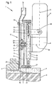
- the two different positions of the cutter disk 11 can be seen with respect to the housing 12, namely on the one hand, the rest position and on the other hand, the working position of the cutter disk 11th In the rest position, the cutter disk 11 is in the housing 12, whereas the working position is characterized in that the cutter disk 11 protrudes from the housing 12 about three to five centimeters. In the working position, it is therefore ensured that the milling disk 11 can cut through the metal clip 5 located in the plaster 4.
- the housing 12 is formed in two parts, namely the housing 12 consists of a fixedly attached to the hand tool 1 first housing part 13 and a relative to the first housing part 13 and thus also to the milling disc 11 adjustable second housing part 14th
- the figure 2 it can be seen that the first housing part 13 is fixedly attached by means of a retaining clip 28 to the hand tool 1.
- a retaining clip 28 Centric in the housing part 13 to a bore is provided, through which the drive flange 9 is passed and thus completely enclosed by the housing part 13.
- two guide sections 26 are provided in the housing part 13, each receiving a guide pin 27 firmly locked on the second housing part 14. The guide pins 27 thus slide in the two guide portions 26 in the adjustment direction of the second housing part fourteenth
- the springs 29 are arranged, which are loaded upon pressing the Frässay 11 to train and thus return the second housing part 14 after completion of the operation again in the rest position.
- the springs 29 are attached to the guide pins 27 between the first housing part 13 and the second housing part 14.
- the springs 29 are arranged laterally next to the housing part 13 and the guide pins 27.
- the mutually facing end faces of the two housing parts 13 and 14 form a stop, so that the freedom of movement of the second housing part 14 is limited.
- the second housing part 14 consists of an upper guide pin receiving plate 24 and a lower plate 25 which is formed in the region of the outlet opening 15 as a guide member 23.
- the lower plate 25 is fastened to the upper plate 24 by means of two adjusting screws 30. Between the two plates 24 and 25 can in the range of the adjusting screw 30 - not shown - spacers are used, so that leaves the distance between the two plates 24 and 25 for receiving different thickness of cutting discs 11 can be set arbitrarily.
- the upper plate 24 has in the region of the drive flange 9 a Parting plane to quickly change the cutter disk 11 can.
- Both Components of the plate 24 are by means of the guide pins 27 to each other solvable fastened, by the fact that in the end faces of the guide pins 27th Threaded holes are incorporated, in each of which a countersunk screw screwed is. In this way, the housing 12 can almost completely from the milling disc 11 be removed.
- a contact plate 31 is provided by means of two Holding leg 32 is locked to the housing 12 adjustable in height.
- the investment plate 31 serves as a voltage applied to the window frame 2 guide member 23 by means of Height adjustment of the contact plate 31 can therefore be the distance between the Milling disk 11 and the window frame 2 are set reliably, without in that the intended guidance of the linear movement of the manual tool 1 get lost.
- the holding legs 32 are locked by means of a screw 33 in a respective sleeve 38.
- Each of the two sleeves 38 has a threaded bore 39, through which in each case one in the housing 12 in bearing bushes 37 rotatably mounted threaded spindle 34 protrudes.
- the two threaded spindles 34 are positively connected by means of a connecting pin 35 on the opposite side of the outlet opening 15 of the milling disk 11.
- a protruding from this adjusting screw 36 is mounted in the housing 12, which cooperates positively with one of the two threaded spindles 34.
- the connecting pin 35 is also rotatably mounted in the housing 12 by means of two bearing bushes 37.
- the threaded spindles 34 rotate because they are connected via bevel gears with the connecting pin 35 in engagement, so that the arranged on these sleeves 38 are moved synchronously.
- the distance of the contact plate 31 can be changed by the cutter disk 11.
Landscapes
- Engineering & Computer Science (AREA)
- Mechanical Engineering (AREA)
- Life Sciences & Earth Sciences (AREA)
- Mining & Mineral Resources (AREA)
- Wood Science & Technology (AREA)
- Forests & Forestry (AREA)
- Milling Processes (AREA)
- Processing Of Stones Or Stones Resemblance Materials (AREA)
- Grinding-Machine Dressing And Accessory Apparatuses (AREA)
Claims (16)
- Outil à main (1) servant en particulier au sectionnement d'un clip métallique (5) dans un murage (4), comprenant un disque de fraisage (11) disposé dans un boítier (12) fixé sur l'outil à main (1) et entraíné via une bride d'entraínement (9) par le moteur d'entraínement (8) de l'outil à main (1), la face frontale du boítier (12) donnant vers le clip métallique (5) comportant une ouverture de sortie (15) pour le disque de fraisage (11), permettant au moins partiellement au disque de fraisage (11) de saillir du boítier (12) et ou, de préférence sur la face opposée à l'ouverture de sortie (15), il est prévu un canal de sortie (16) sur le boítier, la paroi extérieure du boítier (12) opposée à la bride d'entraínement (9) formant un élément de guidage,
caractérisé en ce que
la paroi extérieure du boítier (12) opposée à la bride d'entraínement (9) est plane, que sur le boítier (12), il est prévu une plaque de retient (31) dont l'écartement du disque de fraisage (11) est réglable et qui comporté également un élément de guidage (23), que dans le disque de fraisage (11), il est centré un perçage (17), que dans la bride d'entraínement (9), il est centré un taraudage (18) et que le disque de fraisage (11) est fixé sur la bride d'entraínement (9) au moyen d'une vis à tête fraisée (19) munie d'un filet extérieur et vissée dans le taraudage (18). - Outil à main d'après la revendication 1,
caractérisé en ce que,
au niveau de l'ouverture de sortie (15) sur le boítier (12), il est prévu un collet de support (21) comportant une face de portée (22) perpendiculaire à l'ouverture de sortie (15). - Outil à main d'après la revendication 2,
caractérisé en ce que
la plaque de retient (31) comporte deux bras de retient (32) disposés sur le côté du boítier (12) et orientés perpendiculairement à la plaque de retient (31) et que les bras de retient (32) respectifs s'appuient d'une manière mobile, au moyen de l'élément de fixation (33), sur le boítier (12) de l'outil à main (1). - Outil à main d'après la revendication 2 ou 3,
caractérisé en ce que
la plaque de retient (31) est retenue sur deux broches filetées (34) logées dans le boítier (12) et que les deux broches filetées (34) sont raccordées par un goujon de raccordement (35) de sorte à provoquer leurs mouvements mutuels. - Outil à main d'après la revendication 4,
caractérisé en ce que
sur une des deux broches filetées (34), il est prévu, saillant du boítier (12) et logée dans le boítier (12) de l'outil à main (1), une vis (36) pour le réglage en hauteur de la plaque de retient (31 ). - Outil à main d'après une des revendications précédentes,
caractérisé en ce que,
à côté du taraudage (18), la bride d'entraínement (9) est munie d'au moins deux alésages et que sur le disque de fraisage (11), il est disposé au moins deux goujons de cisaillement (20) s'engrenant dans l'alésage de la bride d'entraínement (9). - Outil à main d'après une des revendications précédentes,
caractérisé en ce que
le boítier (12) se laisse régler relativement par rapport au disque de fraisage (11). - Outil à main d'après la revendication 7,
caractérisé en ce que
le boítier (12) est conçu en deux parties, que la première partie (13) du boítier est solidaire de l'outil à main (1) et que la deuxième partie (14) du boítier s'appuie de manière réglable sur la première partie (13) du boítier. - Outil à main d'après la revendication 8,
caractérisé en ce que
dans la première partie (13) du boítier, il est prévu au moins deux sections de guidage (26) orientées dans le sens de réglage de la deuxième partie (14) du boítier et que dans les sections de guidage (26), il est disposé sur la deuxième partie (14) du boítier respectivement un goujon (27) ajustable. - Outil à main d'après la revendication 8 ou 9,
caractérisé en ce que,
entre les deux parties (13, 14) du boítier, il est inséré au moins un ressort (29). - Outil à main d'après la revendication 8, 9 ou 10,
caractérisé en ce que
la deuxième partie (14) du boítier est formée par une plaque supérieure (24) recevant les goujons (27) et par une plaque inférieure (25) et que les deux plaques (24, 25) sont liées de manière détachable. - Outil à main d'après la revendication 11,
caractérisé en ce que
la plaque supérieure (24) est conçue en deux parties et que les goujons (27) sur ses deux faces frontales sont fixés par des vis sur les deux parties (24', 24") de la plaque. - Outil à main d'après la revendication 12,
caractérisé en ce que
le plan de séparation des deux parties supérieures (24', 24") de la plaque se trouve au niveau de la bride d'entraínement (9) de l'outil à main (1). - Outil à main d'après une des revendications 11 à 13,
caractérisé en ce que,
entre la plaque supérieure (24) et la plaque inférieure (25), il est disposé plusieurs éléments d'écartement. - Outil à main d'après une des revendications précédentes,
caractérisé en ce que
l'axe longitudinal (7) de l'outil à main (1) est orienté perpendiculairement par rapport à l'axe longitudinal (10) de la bride d'entraínement (9). - Outil à main d'après une des revendications précédentes,
caractérisé en ce que
le canal de sortie (16) du boítier (12) est raccordé à une chambre collectrice.
Applications Claiming Priority (2)
| Application Number | Priority Date | Filing Date | Title |
|---|---|---|---|
| DE29909449U DE29909449U1 (de) | 1999-05-29 | 1999-05-29 | Handarbeitsgerät |
| DE29909449U | 1999-05-29 |
Publications (3)
| Publication Number | Publication Date |
|---|---|
| EP1059140A2 EP1059140A2 (fr) | 2000-12-13 |
| EP1059140A3 EP1059140A3 (fr) | 2002-09-11 |
| EP1059140B1 true EP1059140B1 (fr) | 2004-03-10 |
Family
ID=8074146
Family Applications (1)
| Application Number | Title | Priority Date | Filing Date |
|---|---|---|---|
| EP00110771A Expired - Lifetime EP1059140B1 (fr) | 1999-05-29 | 2000-05-20 | Outil à main |
Country Status (4)
| Country | Link |
|---|---|
| EP (1) | EP1059140B1 (fr) |
| AT (1) | ATE261345T1 (fr) |
| DE (2) | DE29909449U1 (fr) |
| ES (1) | ES2216761T3 (fr) |
Families Citing this family (4)
| Publication number | Priority date | Publication date | Assignee | Title |
|---|---|---|---|---|
| DE102005008825A1 (de) * | 2005-02-22 | 2006-08-31 | Popp, Siegfried | Gerät zum Trennen, Schleifen oder dergleichen sowie Gehäuseeinheit für ein Gerät |
| DE102005021212B4 (de) * | 2005-05-07 | 2018-05-09 | Eberhard Berhalter | Handarbeitsgerät |
| DE202008013556U1 (de) | 2008-10-15 | 2009-02-26 | Popp, Siegfried | Höhenverstellung für eine Schutz- oder Führungseinrichtung für ein Trenn- oder Schleifgerät |
| DE102016103151A1 (de) * | 2016-02-23 | 2017-08-24 | Eberhard Berhalter | Werkzeugmaschine |
Family Cites Families (17)
| Publication number | Priority date | Publication date | Assignee | Title |
|---|---|---|---|---|
| DE498645C (de) * | 1929-02-14 | 1930-05-24 | Gustav Flebbe | Vorrichtung zur Herstellung von Nuten, Rillen oder aehnlichen Vertiefungen in Steinen, Mauerwerk o. dgl. |
| DE878269C (de) * | 1951-12-29 | 1953-06-01 | Karl M Reich Fa | Befestigung fuer Kreissaegeblaetter |
| US2688347A (en) * | 1953-07-03 | 1954-09-07 | Menno D Schmidt | Adjustable guide for portable saws |
| FR1122360A (fr) * | 1955-02-22 | 1956-09-05 | Valbo Stella | Montage de scie circulaire à protecteur amovible pour machines électriques portatives |
| US2823713A (en) * | 1956-03-19 | 1958-02-18 | William L Goldsmith | Power kerfing saw |
| FR1231379A (fr) * | 1959-02-18 | 1960-09-28 | Machine portative à couper et à meuler, équipée d'un capot de protection et de patins de guidage | |
| DE1121968B (de) * | 1960-05-05 | 1962-01-11 | Ackermann & Schmitt K G | Schutz- und Absaugegehaeuse fuer Handschleif- oder dergleichen Maschinen |
| EP0062253A1 (fr) * | 1981-04-07 | 1982-10-13 | TOMESANI Società a Responsabilità Limitata | Scie circulaire portative pour le travail du bois |
| DE3239986A1 (de) * | 1982-10-28 | 1984-05-03 | Robert Bosch Gmbh, 7000 Stuttgart | Handwerkzeugmaschine mit einem kreisscheibenfoermigen werkzeug |
| DE3635159C2 (de) * | 1986-10-16 | 1998-05-07 | Bosch Gmbh Robert | Handwerkzeugmaschine mit einer Auflageplatte und einem Parallelanschlag |
| DE3722818A1 (de) * | 1987-07-10 | 1989-01-19 | Robert Wolff | Vorrichtung zum fraesen von nuten oder schattenfugen |
| IT218080Z2 (it) * | 1988-10-25 | 1992-03-30 | Bolzoni Emilio | Carter di protezione per utensili a disco rotante |
| US5031364A (en) * | 1989-03-29 | 1991-07-16 | Monogram Industries, Inc. | Fastener pintail shaving tool |
| DE9202769U1 (de) * | 1992-03-03 | 1992-06-17 | Batschari, Constantin, 6368 Bad Vilbel | Wandschlitzfräse |
| DE19528494A1 (de) * | 1995-08-03 | 1997-02-06 | Leo Klapperich | Vorrichtung zum Fräsen von Nuten, Schattenfugen o. dgl. |
| GB2309411A (en) * | 1996-01-23 | 1997-07-30 | Chi Pin Lee | Mortise making attachment for a machine tool |
| US5829499A (en) * | 1998-01-07 | 1998-11-03 | Liao; Juei-Seng | Wood planing machine |
-
1999
- 1999-05-29 DE DE29909449U patent/DE29909449U1/de not_active Expired - Lifetime
-
2000
- 2000-05-20 ES ES00110771T patent/ES2216761T3/es not_active Expired - Lifetime
- 2000-05-20 AT AT00110771T patent/ATE261345T1/de not_active IP Right Cessation
- 2000-05-20 EP EP00110771A patent/EP1059140B1/fr not_active Expired - Lifetime
- 2000-05-20 DE DE50005574T patent/DE50005574D1/de not_active Expired - Lifetime
Also Published As
| Publication number | Publication date |
|---|---|
| EP1059140A2 (fr) | 2000-12-13 |
| ATE261345T1 (de) | 2004-03-15 |
| DE50005574D1 (de) | 2004-04-15 |
| EP1059140A3 (fr) | 2002-09-11 |
| DE29909449U1 (de) | 2000-10-05 |
| ES2216761T3 (es) | 2004-11-01 |
Similar Documents
| Publication | Publication Date | Title |
|---|---|---|
| DE69206191T2 (de) | Zapfenverbindungshilfsgerät für Handoberfräse. | |
| DE2838233A1 (de) | Tragbare mehrzweckvorrichtung zur herstellung von kreisabschnittfoermigen nuten | |
| AT391645B (de) | Lehrenvorrichtung fuer moebelteile | |
| DE3606525A1 (de) | Fuehrungseinrichtung fuer elektrohandwerkzeuge | |
| DE19748289C2 (de) | Bearbeitungsvorrichtung | |
| EP1059140B1 (fr) | Outil à main | |
| DE3920462A1 (de) | Vorrichtung zur herstellung von oeffnungen oder dgl. an rahmen | |
| DE4209778A1 (de) | Schneidwerkzeug | |
| DE4035512C1 (fr) | ||
| EP0674962B1 (fr) | Dispositif pour la coupe en longueur de profilés creux | |
| DE10258567B4 (de) | Vorrichtung zur Stanzbearbeitung einer Leiste, insbesondere einer Sockelleiste | |
| DE3918710C2 (de) | Gehrungssäge für Glashalteleisten | |
| DE3422101C2 (fr) | ||
| DE2415006C3 (de) | Verfahren zur Herstellung von Fensterrahmen mit Glashalteleiste aus Holz und Vorrichtung zur Durchführung des Verfahrens | |
| DE4494265C2 (de) | Schneidlehre zum Herstellen von bogenförmigen Nuten für Lammellendübel | |
| DE3343787A1 (de) | Schweissraupenverputzmaschine mit verstellbaren anschlaegen fuer fensterrahmen od. dgl. aus kunststoff | |
| EP1038645B1 (fr) | Procédé et appareil pour travailler une parclose, de préférence pour coupes d'onglets, pour cadres de fenêtres, en particulier avec angles aigus ou obtus dans les coins du cadre | |
| EP0167112B1 (fr) | Procédé et appareil pour fraiser et rainurer des parties d'un cadre en bois | |
| DE4401044B4 (de) | Hobelmaschine | |
| DE3939564C2 (fr) | ||
| EP0339177A2 (fr) | Dispositif de sciage | |
| EP0157161A1 (fr) | Rondins, fraiseuse pour leur réalisation et construction réalisée avec ces rondins | |
| DE3718149C2 (de) | Eckenputzmaschine für Stulpflügel | |
| DE69608372T2 (de) | Werkzeugmaschine für Bearbeitungsvorgänge auf langgestreckten Werkstücken wie Profilen und dergleichen | |
| DE19817656A1 (de) | Handwerkzeugmaschine, insbesondere Stichsäge |
Legal Events
| Date | Code | Title | Description |
|---|---|---|---|
| PUAI | Public reference made under article 153(3) epc to a published international application that has entered the european phase |
Free format text: ORIGINAL CODE: 0009012 |
|
| AK | Designated contracting states |
Kind code of ref document: A2 Designated state(s): AT BE CH CY DE DK ES FI FR GB GR IE IT LI LU MC NL PT SE |
|
| AX | Request for extension of the european patent |
Free format text: AL;LT;LV;MK;RO;SI |
|
| RIC1 | Information provided on ipc code assigned before grant |
Free format text: 7B 23Q 11/00 A, 7B 23Q 9/00 B, 7B 28D 1/18 B |
|
| PUAL | Search report despatched |
Free format text: ORIGINAL CODE: 0009013 |
|
| RIC1 | Information provided on ipc code assigned before grant |
Free format text: 7B 23Q 11/00 A, 7B 23Q 9/00 B, 7B 28D 1/18 B, 7B 27B 5/32 B, 7B 23C 5/26 B |
|
| AK | Designated contracting states |
Kind code of ref document: A3 Designated state(s): AT BE CH CY DE DK ES FI FR GB GR IE IT LI LU MC NL PT SE |
|
| AX | Request for extension of the european patent |
Free format text: AL;LT;LV;MK;RO;SI |
|
| 17P | Request for examination filed |
Effective date: 20020808 |
|
| 17Q | First examination report despatched |
Effective date: 20021007 |
|
| REG | Reference to a national code |
Ref country code: GB Ref legal event code: FG4D Free format text: NOT ENGLISH |
|
| AKX | Designation fees paid |
Designated state(s): AT BE CH CY DE DK ES FI FR GB GR IE IT LI LU MC NL PT SE |
|
| GRAP | Despatch of communication of intention to grant a patent |
Free format text: ORIGINAL CODE: EPIDOSNIGR1 |
|
| GRAS | Grant fee paid |
Free format text: ORIGINAL CODE: EPIDOSNIGR3 |
|
| GRAA | (expected) grant |
Free format text: ORIGINAL CODE: 0009210 |
|
| AK | Designated contracting states |
Kind code of ref document: B1 Designated state(s): AT BE CH CY DE DK ES FI FR GB GR IE IT LI LU MC NL PT SE |
|
| PG25 | Lapsed in a contracting state [announced via postgrant information from national office to epo] |
Ref country code: FI Free format text: LAPSE BECAUSE OF FAILURE TO SUBMIT A TRANSLATION OF THE DESCRIPTION OR TO PAY THE FEE WITHIN THE PRESCRIBED TIME-LIMIT Effective date: 20040310 Ref country code: NL Free format text: LAPSE BECAUSE OF FAILURE TO SUBMIT A TRANSLATION OF THE DESCRIPTION OR TO PAY THE FEE WITHIN THE PRESCRIBED TIME-LIMIT Effective date: 20040310 Ref country code: CY Free format text: LAPSE BECAUSE OF FAILURE TO SUBMIT A TRANSLATION OF THE DESCRIPTION OR TO PAY THE FEE WITHIN THE PRESCRIBED TIME-LIMIT Effective date: 20040310 Ref country code: IE Free format text: LAPSE BECAUSE OF FAILURE TO SUBMIT A TRANSLATION OF THE DESCRIPTION OR TO PAY THE FEE WITHIN THE PRESCRIBED TIME-LIMIT Effective date: 20040310 |
|
| REG | Reference to a national code |
Ref country code: CH Ref legal event code: EP |
|
| REG | Reference to a national code |
Ref country code: IE Ref legal event code: FG4D Free format text: GERMAN |
|
| REF | Corresponds to: |
Ref document number: 50005574 Country of ref document: DE Date of ref document: 20040415 Kind code of ref document: P |
|
| PG25 | Lapsed in a contracting state [announced via postgrant information from national office to epo] |
Ref country code: LU Free format text: LAPSE BECAUSE OF NON-PAYMENT OF DUE FEES Effective date: 20040520 |
|
| PG25 | Lapsed in a contracting state [announced via postgrant information from national office to epo] |
Ref country code: BE Free format text: LAPSE BECAUSE OF NON-PAYMENT OF DUE FEES Effective date: 20040531 Ref country code: MC Free format text: LAPSE BECAUSE OF NON-PAYMENT OF DUE FEES Effective date: 20040531 |
|
| PG25 | Lapsed in a contracting state [announced via postgrant information from national office to epo] |
Ref country code: DK Free format text: LAPSE BECAUSE OF FAILURE TO SUBMIT A TRANSLATION OF THE DESCRIPTION OR TO PAY THE FEE WITHIN THE PRESCRIBED TIME-LIMIT Effective date: 20040610 Ref country code: GR Free format text: LAPSE BECAUSE OF FAILURE TO SUBMIT A TRANSLATION OF THE DESCRIPTION OR TO PAY THE FEE WITHIN THE PRESCRIBED TIME-LIMIT Effective date: 20040610 |
|
| REG | Reference to a national code |
Ref country code: SE Ref legal event code: TRGR |
|
| GBT | Gb: translation of ep patent filed (gb section 77(6)(a)/1977) |
Effective date: 20040625 |
|
| NLV1 | Nl: lapsed or annulled due to failure to fulfill the requirements of art. 29p and 29m of the patents act | ||
| REG | Reference to a national code |
Ref country code: IE Ref legal event code: FD4D |
|
| REG | Reference to a national code |
Ref country code: ES Ref legal event code: FG2A Ref document number: 2216761 Country of ref document: ES Kind code of ref document: T3 |
|
| BERE | Be: lapsed |
Owner name: BERHALTER, EBERHARD Effective date: 20040531 |
|
| ET | Fr: translation filed | ||
| PLBE | No opposition filed within time limit |
Free format text: ORIGINAL CODE: 0009261 |
|
| STAA | Information on the status of an ep patent application or granted ep patent |
Free format text: STATUS: NO OPPOSITION FILED WITHIN TIME LIMIT |
|
| 26N | No opposition filed |
Effective date: 20041213 |
|
| PG25 | Lapsed in a contracting state [announced via postgrant information from national office to epo] |
Ref country code: PT Free format text: LAPSE BECAUSE OF NON-PAYMENT OF DUE FEES Effective date: 20040810 |
|
| PGFP | Annual fee paid to national office [announced via postgrant information from national office to epo] |
Ref country code: SE Payment date: 20090528 Year of fee payment: 10 Ref country code: IT Payment date: 20090526 Year of fee payment: 10 Ref country code: AT Payment date: 20090526 Year of fee payment: 10 |
|
| PG25 | Lapsed in a contracting state [announced via postgrant information from national office to epo] |
Ref country code: AT Free format text: LAPSE BECAUSE OF NON-PAYMENT OF DUE FEES Effective date: 20100520 |
|
| EUG | Se: european patent has lapsed | ||
| PG25 | Lapsed in a contracting state [announced via postgrant information from national office to epo] |
Ref country code: SE Free format text: LAPSE BECAUSE OF NON-PAYMENT OF DUE FEES Effective date: 20100521 Ref country code: IT Free format text: LAPSE BECAUSE OF NON-PAYMENT OF DUE FEES Effective date: 20100520 |
|
| REG | Reference to a national code |
Ref country code: FR Ref legal event code: PLFP Year of fee payment: 16 |
|
| PGFP | Annual fee paid to national office [announced via postgrant information from national office to epo] |
Ref country code: ES Payment date: 20150520 Year of fee payment: 16 |
|
| REG | Reference to a national code |
Representative=s name: PATENT- UND RECHTSANWALTSKANZLEI DAUB, DE Ref country code: DE Ref legal event code: R082 Ref document number: 50005574 Country of ref document: DE |
|
| REG | Reference to a national code |
Ref country code: FR Ref legal event code: PLFP Year of fee payment: 17 |
|
| REG | Reference to a national code |
Ref country code: CH Ref legal event code: PCOW Free format text: NEW ADDRESS: RATTENWEILER 12, 88069 TETTNANG (DE) Ref country code: CH Ref legal event code: NV Representative=s name: PATENTANWALTSKANZLEI DAUB, CH |
|
| REG | Reference to a national code |
Ref country code: FR Ref legal event code: PLFP Year of fee payment: 18 |
|
| REG | Reference to a national code |
Ref country code: FR Ref legal event code: PLFP Year of fee payment: 19 |
|
| PG25 | Lapsed in a contracting state [announced via postgrant information from national office to epo] |
Ref country code: ES Free format text: LAPSE BECAUSE OF NON-PAYMENT OF DUE FEES Effective date: 20160521 |
|
| REG | Reference to a national code |
Ref country code: ES Ref legal event code: FD2A Effective date: 20180625 |
|
| REG | Reference to a national code |
Ref country code: CH Ref legal event code: PCAR Free format text: NEW ADDRESS: LEUTSCHENBACHSTRASSE 95, 8050 ZUERICH (CH) |
|
| PGFP | Annual fee paid to national office [announced via postgrant information from national office to epo] |
Ref country code: DE Payment date: 20190522 Year of fee payment: 20 |
|
| PGFP | Annual fee paid to national office [announced via postgrant information from national office to epo] |
Ref country code: FR Payment date: 20190521 Year of fee payment: 20 |
|
| PGFP | Annual fee paid to national office [announced via postgrant information from national office to epo] |
Ref country code: CH Payment date: 20190523 Year of fee payment: 20 |
|
| PGFP | Annual fee paid to national office [announced via postgrant information from national office to epo] |
Ref country code: GB Payment date: 20190523 Year of fee payment: 20 |
|
| REG | Reference to a national code |
Ref country code: DE Ref legal event code: R071 Ref document number: 50005574 Country of ref document: DE |
|
| REG | Reference to a national code |
Ref country code: CH Ref legal event code: PL |
|
| REG | Reference to a national code |
Ref country code: GB Ref legal event code: PE20 Expiry date: 20200519 |
|
| PG25 | Lapsed in a contracting state [announced via postgrant information from national office to epo] |
Ref country code: GB Free format text: LAPSE BECAUSE OF EXPIRATION OF PROTECTION Effective date: 20200519 |