EP1059146A2 - Multiblock-Robot System - Google Patents
Multiblock-Robot System Download PDFInfo
- Publication number
- EP1059146A2 EP1059146A2 EP00110346A EP00110346A EP1059146A2 EP 1059146 A2 EP1059146 A2 EP 1059146A2 EP 00110346 A EP00110346 A EP 00110346A EP 00110346 A EP00110346 A EP 00110346A EP 1059146 A2 EP1059146 A2 EP 1059146A2
- Authority
- EP
- European Patent Office
- Prior art keywords
- units
- flange
- multiblock
- multiblock robot
- plug
- Prior art date
- Legal status (The legal status is an assumption and is not a legal conclusion. Google has not performed a legal analysis and makes no representation as to the accuracy of the status listed.)
- Withdrawn
Links
Images


Classifications
-
- B—PERFORMING OPERATIONS; TRANSPORTING
- B25—HAND TOOLS; PORTABLE POWER-DRIVEN TOOLS; MANIPULATORS
- B25J—MANIPULATORS; CHAMBERS PROVIDED WITH MANIPULATION DEVICES
- B25J9/00—Program-controlled manipulators
- B25J9/08—Program-controlled manipulators characterised by modular constructions
-
- B—PERFORMING OPERATIONS; TRANSPORTING
- B63—SHIPS OR OTHER WATERBORNE VESSELS; RELATED EQUIPMENT
- B63B—SHIPS OR OTHER WATERBORNE VESSELS; EQUIPMENT FOR SHIPPING
- B63B3/00—Hulls characterised by their structure or component parts
- B63B3/02—Hulls assembled from prefabricated sub-units
- B63B3/08—Hulls assembled from prefabricated sub-units with detachably-connected sub-units
-
- B—PERFORMING OPERATIONS; TRANSPORTING
- B63—SHIPS OR OTHER WATERBORNE VESSELS; RELATED EQUIPMENT
- B63B—SHIPS OR OTHER WATERBORNE VESSELS; EQUIPMENT FOR SHIPPING
- B63B35/00—Vessels or similar floating structures specially adapted for specific purposes and not otherwise provided for
-
- B—PERFORMING OPERATIONS; TRANSPORTING
- B63—SHIPS OR OTHER WATERBORNE VESSELS; RELATED EQUIPMENT
- B63B—SHIPS OR OTHER WATERBORNE VESSELS; EQUIPMENT FOR SHIPPING
- B63B35/00—Vessels or similar floating structures specially adapted for specific purposes and not otherwise provided for
- B63B35/28—Barges or lighters
-
- B—PERFORMING OPERATIONS; TRANSPORTING
- B63—SHIPS OR OTHER WATERBORNE VESSELS; RELATED EQUIPMENT
- B63B—SHIPS OR OTHER WATERBORNE VESSELS; EQUIPMENT FOR SHIPPING
- B63B35/00—Vessels or similar floating structures specially adapted for specific purposes and not otherwise provided for
- B63B35/44—Floating buildings, stores, drilling platforms, or workshops, e.g. carrying water-oil separating devices
-
- B—PERFORMING OPERATIONS; TRANSPORTING
- B63—SHIPS OR OTHER WATERBORNE VESSELS; RELATED EQUIPMENT
- B63B—SHIPS OR OTHER WATERBORNE VESSELS; EQUIPMENT FOR SHIPPING
- B63B35/00—Vessels or similar floating structures specially adapted for specific purposes and not otherwise provided for
- B63B35/66—Tugs
- B63B35/70—Tugs for pushing
-
- B—PERFORMING OPERATIONS; TRANSPORTING
- B63—SHIPS OR OTHER WATERBORNE VESSELS; RELATED EQUIPMENT
- B63G—OFFENSIVE OR DEFENSIVE ARRANGEMENTS ON VESSELS; MINE-LAYING; MINE-SWEEPING; SUBMARINES; AIRCRAFT CARRIERS
- B63G8/00—Underwater vessels, e.g. submarines; Equipment specially adapted therefor
- B63G8/001—Underwater vessels adapted for special purposes, e.g. unmanned underwater vessels; Equipment specially adapted therefor, e.g. docking stations
-
- B—PERFORMING OPERATIONS; TRANSPORTING
- B64—AIRCRAFT; AVIATION; COSMONAUTICS
- B64G—COSMONAUTICS; VEHICLES OR EQUIPMENT THEREFOR
- B64G1/00—Cosmonautic vehicles
- B64G1/10—Artificial satellites; Systems of such satellites; Interplanetary vehicles
- B64G1/12—Artificial satellites; Systems of such satellites; Interplanetary vehicles manned
-
- E—FIXED CONSTRUCTIONS
- E21—EARTH OR ROCK DRILLING; MINING
- E21B—EARTH OR ROCK DRILLING; OBTAINING OIL, GAS, WATER, SOLUBLE OR MELTABLE MATERIALS OR A SLURRY OF MINERALS FROM WELLS
- E21B7/00—Special methods or apparatus for drilling
- E21B7/12—Underwater drilling
- E21B7/124—Underwater drilling with underwater tool drive prime mover, e.g. portable drilling rigs for use on underwater floors
-
- B—PERFORMING OPERATIONS; TRANSPORTING
- B63—SHIPS OR OTHER WATERBORNE VESSELS; RELATED EQUIPMENT
- B63B—SHIPS OR OTHER WATERBORNE VESSELS; EQUIPMENT FOR SHIPPING
- B63B35/00—Vessels or similar floating structures specially adapted for specific purposes and not otherwise provided for
- B63B35/44—Floating buildings, stores, drilling platforms, or workshops, e.g. carrying water-oil separating devices
- B63B2035/4426—Stationary floating buildings for human use, e.g. floating dwellings or floating restaurants
-
- B—PERFORMING OPERATIONS; TRANSPORTING
- B63—SHIPS OR OTHER WATERBORNE VESSELS; RELATED EQUIPMENT
- B63G—OFFENSIVE OR DEFENSIVE ARRANGEMENTS ON VESSELS; MINE-LAYING; MINE-SWEEPING; SUBMARINES; AIRCRAFT CARRIERS
- B63G8/00—Underwater vessels, e.g. submarines; Equipment specially adapted therefor
- B63G8/001—Underwater vessels adapted for special purposes, e.g. unmanned underwater vessels; Equipment specially adapted therefor, e.g. docking stations
- B63G2008/002—Underwater vessels adapted for special purposes, e.g. unmanned underwater vessels; Equipment specially adapted therefor, e.g. docking stations unmanned
- B63G2008/004—Underwater vessels adapted for special purposes, e.g. unmanned underwater vessels; Equipment specially adapted therefor, e.g. docking stations unmanned autonomously operating
-
- B—PERFORMING OPERATIONS; TRANSPORTING
- B64—AIRCRAFT; AVIATION; COSMONAUTICS
- B64G—COSMONAUTICS; VEHICLES OR EQUIPMENT THEREFOR
- B64G1/00—Cosmonautic vehicles
- B64G1/22—Parts of, or equipment specially adapted for fitting in or to, cosmonautic vehicles
- B64G1/64—Systems for coupling or separating cosmonautic vehicles or parts thereof, e.g. docking arrangements
- B64G1/646—Docking or rendezvous systems
- B64G1/6462—Docking or rendezvous systems characterised by the means for engaging other vehicles
-
- G—PHYSICS
- G05—CONTROLLING; REGULATING
- G05B—CONTROL OR REGULATING SYSTEMS IN GENERAL; FUNCTIONAL ELEMENTS OF SUCH SYSTEMS; MONITORING OR TESTING ARRANGEMENTS FOR SUCH SYSTEMS OR ELEMENTS
- G05B2219/00—Program-control systems
- G05B2219/30—Nc systems
- G05B2219/40—Robotics, robotics mapping to robotics vision
- G05B2219/40304—Modular structure
-
- Y—GENERAL TAGGING OF NEW TECHNOLOGICAL DEVELOPMENTS; GENERAL TAGGING OF CROSS-SECTIONAL TECHNOLOGIES SPANNING OVER SEVERAL SECTIONS OF THE IPC; TECHNICAL SUBJECTS COVERED BY FORMER USPC CROSS-REFERENCE ART COLLECTIONS [XRACs] AND DIGESTS
- Y02—TECHNOLOGIES OR APPLICATIONS FOR MITIGATION OR ADAPTATION AGAINST CLIMATE CHANGE
- Y02A—TECHNOLOGIES FOR ADAPTATION TO CLIMATE CHANGE
- Y02A30/00—Adapting or protecting infrastructure or their operation
-
- Y—GENERAL TAGGING OF NEW TECHNOLOGICAL DEVELOPMENTS; GENERAL TAGGING OF CROSS-SECTIONAL TECHNOLOGIES SPANNING OVER SEVERAL SECTIONS OF THE IPC; TECHNICAL SUBJECTS COVERED BY FORMER USPC CROSS-REFERENCE ART COLLECTIONS [XRACs] AND DIGESTS
- Y10—TECHNICAL SUBJECTS COVERED BY FORMER USPC
- Y10T—TECHNICAL SUBJECTS COVERED BY FORMER US CLASSIFICATION
- Y10T74/00—Machine element or mechanism
- Y10T74/20—Control lever and linkage systems
- Y10T74/20207—Multiple controlling elements for single controlled element
- Y10T74/20305—Robotic arm
- Y10T74/20317—Robotic arm including electric motor
-
- Y—GENERAL TAGGING OF NEW TECHNOLOGICAL DEVELOPMENTS; GENERAL TAGGING OF CROSS-SECTIONAL TECHNOLOGIES SPANNING OVER SEVERAL SECTIONS OF THE IPC; TECHNICAL SUBJECTS COVERED BY FORMER USPC CROSS-REFERENCE ART COLLECTIONS [XRACs] AND DIGESTS
- Y10—TECHNICAL SUBJECTS COVERED BY FORMER USPC
- Y10T—TECHNICAL SUBJECTS COVERED BY FORMER US CLASSIFICATION
- Y10T74/00—Machine element or mechanism
- Y10T74/20—Control lever and linkage systems
- Y10T74/20207—Multiple controlling elements for single controlled element
- Y10T74/20305—Robotic arm
- Y10T74/20329—Joint between elements
Definitions
- the invention relates to a multiblock robot system with mutually compatible multiblock robot system standard cells and multiblock robots, both on earth, in marine technology, in of flight technology and in space.
- U.S. Patent 5,241,875, 5,850,762 and 5,852,353 and U.S. Patent application 07 / 986,532, 08 / 865,524, 09 / 298,204, are multiblock robots Systems known. These have the advantage that targeted multiblock robot complete systems to standardized, almost identical multi-block standard parts, which are minimal Effort in development and design can be created with just a few Actions by the users themselves for the originally intended range of effects are used, are interchangeable and also to other robot system solutions can be put together.
- the object of the present invention is to introduce a minimized number of additional ones Multi-block standard parts and the integration of compatible multi-block robot system standard cells and multiblock robots, a standardized covering all areas of life
- Multi-block standard parts and the integration of compatible multi-block robot system standard cells and multiblock robots a standardized covering all areas of life
- To achieve system technology its components overlapping, on earth, in marine technology, in the flight and rocket technology and space technology are used and thus the advantages of flexible multi-axis robot systems due to additional large quantities in all of these Areas of application, in standardization, economical manufacture, functionality and Range of applications, still to be expanded.
- this is achieved in that standardized, mutually Compatible and pluggable stationary and mobile, earth, sea, flight and space-capable Multiblock Robot System standard cells and multiblock robots are formed with minimal Effort in development and construction can be created and by optional combination with each other and with the entire range of all multiblock robot standard parts Targeted, stationary and mobile multiblock robot individual systems and multiblock robot venue, maritime, aviation, and space complexes are formed, which are mutually exclusive are interchangeable and also resolved at any time and to any other multiblock robot system solution can be put together.
- Movement arrows in the figures show the directions of movement of the system parts, solid lines Lines with and without view arrows from Fig. To Fig., The origin and the direction of view for drawn out subviews, sections and system details of the respective figure, dash-dotted Lines the contours of a possible multiblock robot accessory.
- the individual names and Numerical indices are largely analogous to the multiblock mentioned above Robot patents and patent applications taken over or continued.
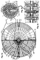
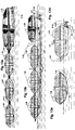
- the Multiblock Robot System standard cells 1-28 are multiblock room units that are conceptually like this are designed like the multiblock robot standard parts and flange attachments according to Basic U.S. Patent 5,241,875 and U.S. patent application 07 / 986,532. You will too almost identical in construction to each other and receive central rotary flange plug connections 2-2 with power and communication channels, horizontally and vertically through the Multiblock Robot System standard cells are led.
- the well-known power and communication channels of the Multiblock Robot standard parts are however with Multiblock Robot System standard cells 1-28, each on request, replaced by supply channels 10-1 ', 9'-40 and access channels 12-1,1-25.
- supply channels 10-1 'supply lines 10-1 of various types, such as Power and communication lines and also equipment liquid supply and discharge lines.
- the supply channels 10-1 ' are depending on the application of the multiblock robot system standard cells 1-28, surrounded by liquid channels 9'-40, the water, fuels, Contain hydraulic fluids and other necessary operating fluids.
- the horizontal Access channels 12-1 serve as person and multiblock robot passages. They are each in the Center of the respective, concentrically arranged, supply and Through channels.
- Access channels 1-25 are vertical channels for cable lift and hydraulic lift flange plug-on units 3-25, for lifting and lowering loads, people and Multiblock robots are provided.
- the vertical access channels 1-25 lie like the horizontal ones Access channels 12-1, each in the center of the supply and concentrically arranged Access channels.
- the vertical access channels 1-25 for elevator equipment are especially with stationary multiblock robot system standard cells 1-28, from staircase facilities 1-25 '' surrounded.
- the vertical supply channels 10-1 'and access channels 1-25 are surrounded by concentric sliding rings 1-16 for material and devices.
- the Multiblock Robot System standard cells 1-28 have intermediate floors 1-30, intermediate walls 1-29 with sliding doors 1-24.
- the outer contour receives a multiblock segment solar flange plug-on unit 9'-27, window openings 1-24 ', an internal input flange plug-on unit 1-26 with sliding doors 1-24 outside and inside and access to the horizontal Access channels 12-1.
- There is an internal, extendable platform flange attachment 1-26 'arranged facing outwards with a parapet is covered.
- the vertical access channels are accessed via the horizontal access channels 1-25 Access channels 1-25.
- the concentric, vertical supply channels 10-1 ', 9'-40 and the vertical access channels 1-25 also sliding doors 1-24.
- Access from the Intermediate floors 1-30 through the concentric sliding rings 1-16 is made possible by the fact that swing them in on their ring tracks 9'-38 and in the area of the sliding doors 1-24 of the vertical ones Access channels 1-25, form an access opening 1-24 ''.
- Access to the intermediate floors 1-30 is also possible from the horizontal access channels 12-1.
- the Side walls of the supply channels 10-1 ', 9'-40 which are located concentrically to one another, likewise Sliding doors 1-24 used.
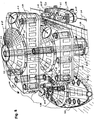
- the entire multiblock robot system cell 1-28 becomes analog to the Multiblock Robot standard parts of the patent specifications and patent applications mentioned in Head and foot position on slewing rings 4-1 and is driven by the drive motors 8-1 Gear ring 25-1, the drive pinion 25-1 of the rotary flange connector 2-2, freely around the Center axis and the vertical supply and access channels 10-1 ', 9'-40.1-25 pivotable. Nevertheless, access to the supply channels 10-1 ', 9'-40 remains in each of the pivoted-in positions and the supply lines 10-1 maintained at all times. However, it will also not be rotatable Flange connectors 2-2 'in the different embodiments, according to U.S. patent 5,850,762.
- the vertical and horizontal supply and access channels 10-1 ', 9'-40, 12-1.1-25 are closed by sliding doors 1-24 and also receive analog to the Multiblock Robot patent specifications and patent applications in header and Foot position and at the horizontal exits and at all positions at the rotary flange plug connections 2-2 or non-rotatable flange plug connections 2-2 'are provided, Plug sockets 2-3 'and plug units 2-3, corresponding clamping and Locking devices, for the plug connection to neighboring rotary flange plug connections 2-2 and flange connections and the connection of the supply and Access lines 10-1 and channels 10-1 ', 1-25.9'-40.12-1 with each other.
- the Supply channels 10-1 are designed as a horizontal ring body with a ring inner and outer wall executed, the supply lines 10-1 are used in the ring body, or else the Ring body with inner and outer wall itself serves as supply line 10-1 and, among other things. liquids forwards.
- the supply channels are alternatively used only from one another in a ring Supply lines 10-1, formed without a ring inner and outer wall and also in a ring-shaped Solid wall and used at intervals from each other, as shown in Fig. 1,2.
- the used In the end position, supply lines 10-1 have plug units 2-3 and plug socket units 2-3 ', which are coated with sealing material 2-3' 'and are conical in such a way that when plugging together a centering effect the opposite rotating flange plug connections 2-2 can be easily put together.
- the connector units 2-3 and connector units 2-3 'on the circumference of the Rotary flange connectors 2-2 only for centering the rotary flange connectors 2-2 are used in the same way as the connector units 2-3 and Connector units 2-3 'executed that the supply lines 10-1 in the Connect supply channels 10-1 'to each other.
- the proximity sensor shown in Fig. 2c Flange plug-on units 9'-21 ensure the alignment of the rotary flange plug-in connections to be plugged together 2-2, with the internal supply channels 10-1 'and supply lines 10-1.
- In the middle is a supply line 10-1 with power and communication lines 3-1 provided and on the right and left, a supply line 10-1 for liquids.
- the multiblock robot system standard cells 1-28 are made up of standard cell subsegments 1-27, 3b, plugged together and are in turn on the plug-in sides and at the ends, for connection to the rotary flange plug connections 2-2, with plug units 2-3 and to the opposite sides, equipped with 2-3 'socket units. Also be through the upper and lower wall supply lines 10-1, which are identical to that Aufsteckdetail according to FIG. 2c, when plugging together the individual standard cell sub-segments 1-27 can be closed into a multiblock robot system standard cell 1-28 and Supply ring lines 10-1 on the periphery, above and below the multiblock robot system standard cell Form 1-28.
- the supply ring lines 10-1 thus formed have in Distances to each other vertical connecting lines 10-1 to the horizontal supply lines 10-1 that surround the horizontal access channels 12-1.
- the supply 10-1 ', 9'-40 and Access channels 1-12, 1-25 and the standard cell subsegments 1-27 are given their circumference in Area of assembly positions conical sealing rings with the sealing material 2-3 '' according to and analogous to FIG. 2b.
- the multiblock robot system standard cells that are plugged next to and on top of each other 1-28 are in the present embodiment at the connection transitions of the rotary flange connectors 2-2 connected by flexible flange plug-on units 18-2.
- the multiblock Robot system standard cells 1-28 are interposed by the flexible ones Flange plug-on units 18-2 on the separate Multiblock Robot standard input flange plug-on unit 1-26 attached. This is with the 2-2 rotary flange connectors Foundation flange plug-on units 9'-19 connected, and with those guided therein Supply lines.
- the foundation flange plug-on units 9'-19 are cast in concrete and also supply channels laid freely under the ground, which in turn supply lines 10-1 guide and in end position rotary flange plug connections 2-2 and non-rotatable flange plug connections 2-2 '.
- the foundation flange plug-on unit 9'-19 on which the Multiblock Robot input flange plug-on unit 1-26 and the Multiblock arranged above Robot system standard cells 1-28 are attached, is a foundation concrete block with integrated Supply channels, from which in any direction via non-rotatable flange connections 2-2 ' freely routed supply channels with integrated supply lines 10-1, such as Sewage pipes, drinking water pipes, fuel pipes, power and communication lines.
- a separate Multiblock Robot standard roof flange attachment 1-32 is in the head position plugged in, except for the different devices, identical to the separate input flange plug-on unit 1-26 is the one provided there with sliding doors 1-24 ' Rotary flange connector 2-2 and the supply and access channels 10-1 ', 1-25, closes. In In this position, multi-block robot hub flange plug-on units 1-31 are attached.
- the torsionally flexible flange plug-on units 18-2 receive supply lines 10-1 and Through channels 12-1,1-25 in twist-pull and flexible plastics.
- the cable and Hydraulic flange plug-on units 3-25 are assembled after connecting the multiblock robot Complete complex, upper lifting ropes and also hydraulic telescopic lifting platforms with the individual Multiblock-Robot Hub-flange attachments 1-31 connected and over the entire height of the Access channels 1-25, from the standard entrance flange plug-on unit 1-26 to the standard roof flange plug-on unit 1-32 raised or lowered .. There is also a continuous transition from a concentric staircase arrangement 1-25 '' to the next one above the assembly of the individual components guaranteed.
- Multi-axis Multiblock Robot articulated arms 9'-14 are provided, which with hydraulics Flange clip-on units according to U.S. patent application 09 / 298.204 are equipped.
- the Multi-axis articulated arms 9'-14 react via seismic sensor flange attachment units 9'-21 self-operating on seismic changes. They safely catch earth movements caused by earthquakes on, have a shock absorber effect and adhere to the entire multiblock robot complex even in the event of sudden Subsidence in an approximately horizontal position.
- the flexible flange plug-on units 18-2 are also bumps and movements on a multiblock robot system standard cell 1-28 become effective, not transferred to the neighboring cells, but by the rotationally flexible Flanged plug-on units 18-2 intercepted.
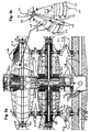
- the embodiment according to FIG. 3 is suitable not only for earthquake areas, storm damage areas and and in unsafe Soil ratios, but also for facilities under water, in difficult Current conditions and for the establishment on other planets.
- the multiblock robot system standard cells 1-28 can have different external contours and have different interiors and exteriors depending on the application.
- the present exemplary embodiments according to FIGS. 4a, 4b are basically identical.
- the Overall complex, according to Fig. 4a has a more spherical outer contour and Overall complex, the Fig. 4b, more a disc-shaped outer contour. It is also for this Overall, a roof flange plug-on unit 1-32 between the two multiblock robot system standard cells 1-28 set, while the three standard Multiblock Robot System cells 1-28, according to 4a, are plugged directly one above the other.
- the interposed roof flange plug-on unit 1-32 accommodates pluggable multiblock robot battery units 9'-6 in the outdoor area Intermediate energy storage of the entire multiblock robot complex and for battery charging of Multiblock robots, thanks to the solar flange attachments 9'-27 on the outer contour of the Multiblock robot system standard cells 1-28.
- the supply lines 10-1 are here in the outer walls of the Elevator channel 1-25 used, which thus serves as supply channel 10-1 'and end in Head and foot position in plug connections of rotary flange plug connections 2-2.
- the single ones Multiblock robot system standard cells 1-28 have two shelves and no partitions, see above that continuous all-round room units are created in the interior. Every shelf is included Position and direction code web guides 3-5 for quick orientation and positioning of multiblock robots according to U.S. patent application 09 / 298,204 executed. Any multiblock Robot system standard cell 1-28 also receives two concentric sliding rings 1-16 which on their circular path guides 9'-38 according to FIG. 2b with the Multiblock Robot Travel drive units 9'-39 are moved separately and swiveled towards each other.
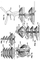
- the Multiblock Robot System standard cells 1-28 are designed for on earth, under water, in flight and Rocket technology and used in space and for a wide variety of applications with corresponding additional equipment, consisting of flange plug-on units and sub-standard cells be combined. At the same time, however, they should also become part of the multiblock robot be compatible and make the multiblock robot system environment even more effective. To do this the multiblock robots with aeronautical and underwater propulsion flange attachments equipped so that they always have easy access to the Multiblock Robot System standard cells 1-28 regardless of the environmental conditions in which they are used.
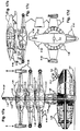
- the aeronautical Execution Multiblock Robot standard parts 2-1 are provided, which are above the head unit can be arranged and plugged in and with floor-only operation for the antenna flange plug-on unit 9'-3 or solar flange plug-on units is provided.
- the attached multiblock Robot standard part 2-1 comes with Multiblock Robot vertical rotor flange attachments 9'-41 and Engine flange plug-on units 9'-42 equipped that operate on the horizontal and vertical Rotary flange plug-in connections 2-2 are attached.
- fuel channels provided in the multiblock robot Standard part 2-1 above the head unit.
- This equipment becomes the multiblock robot standard part 2-1 below the computer unit under FIG.
- Control flange plug-on unit 9'-43 which is a separate control unit for the Take up engine flange attachment units 9'-42, which are centered on the engine flange attachment units 9'-42 is attached.
- Under the control flange attachment 9'-43 is on the Associated vertical rotary flange plug connection 2-2, a separate fuel duct flange plug-on unit 9'-47 attached.
- the antenna flange plug-on unit 9'-3 is mounted on the multiblock Standard part 2-1 repositioned, which is arranged above the multiblock robot belt drive unit.
- the device shown in FIG. 5c is designed for propulsion under water.
- the Multiblock Robot standard part 2-1 a separate fuel duct flange plug-on unit 9'-47 plugged in and assigned to their rotary flange connectors 2-2, left and right, one each plugged in under the water rotor flange plug-on unit 9'-44.
- the fuel duct flange plug-on unit 9'-47 alternatively becomes a multiblock robot battery flange plug-on unit 9'-6, according to the multiblock robot patent U.S. 5,850,762 as a drive unit intended.
- Multiblock robots can be used with aeronautical engine flange mounting units 9'-42 and at the same time under water rotor flange plug-on units 9'-40, as well as with Floor-traveling belt undercarriages can be equipped so that they can be attached without Acceptance of the corresponding flange plug-on units, on the ground, under water and in the Air can be active.
- the multiblock robots with rocket flange attachments are used for space targets 9'-41, according to FIG. 20c, and the associated fuel flange plug-on units 9'-43 and equipped with walking or driving flange attachments.
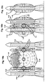
- the ground-based multiblock robot complex comprises three superimposed ones Multiblock robot system standard cells 1-28 according to FIG. 6a. These are each 90 ° pivoted towards each other. They are conceptually identical to each other, only the bottom one Multilblock robot system standard cell 1-28 is different from the outer contour two Multiblock robot system standard cells 1-28 arranged above. The one in the top position The arranged multi-block robot system standard cell 1-28 shows the partially extended one Platform flange attachment 1-26 '. A landing platform flange attachment unit is in the head position with parapet 1-33 attached and a multiblock flight robot landed. The multiblock flying robot is via a hydraulic flange plug-on unit 3-25 inside the vertical Access channels 1-25 lowered into the standard Multiblock Robot System cells 1-28.
- the multiblock robot system standard cell 1-28 plugged in in the floor position of FIG. 7a identical to the multiblock robot system standard cells 1-28 in the head and center position of Fig. 6a.
- this multiblock robot system standard cell 1-28 are three swiveling solar flange plug-on units 9'-51, which are plugged in via the access and supply duct flange plug-on units 9'-50, each with its own rotary flange connectors 2-2 are placed one above the other.
- the access and supply duct flange plug-on units 9'-50 have the same design characteristics as through channels 1-25 of FIG. 1 and received Supply lines 10-1.
- the segment solar flange plug-on units 9'-51 are identical in design to the swiveling segment solar flange plug-on units 9'-27.
- a multiblock vertical wind rotor A 9'-49 flange plug-on unit is plugged in and in the head position is a multiblock wind turbine Flange attachment unit 9'-25 plugged on, according to U.S. Patent 5,852,353.
- the multiblock robot Overall complex according to FIG. 7d, with the three multiblock robot system standard cells plugged one above the other 1-28, carries vertical multiblock solar wind in head position Flange attachment unit 9'-49 'and above is a multiblock robot antenna flange attachment unit 9'-3 attached.
- the Solar-Wind flange attachment unit 9'-49 ' carries on the conical tops of the three vertical wind rotor blade flange mounting units 9'-48, the solar flange mounting units 9'-48 '. This makes it possible for electricity to flow through the solar flange attachments 9'-48 'and vertical wind rotor blade flange plug-on units 9'-52 ', from sun and wind at the same time received, or only by wind, or only by sun, depending on the prevailing weather, and during the day or night time and the current via the inner, vertical supply channel 10-1 ' to the Multiblock Robot System standard cells 1-28 below.
- This multi-block robot complex is located on a quay.
- the two on top of each other arranged Multiblock Robot System standard cells 1-28 have a rectangular contour, with swiveling segment solar flange plug-on unit 9'-27, which is attached to the central, conical roof contour is attached.
- the central, conical roof contour has its own Rotary flange plug connection 2-2 executed in head position.
- another Multiblock Robot System standard cells 1-28 can be plugged in, or other multiblock robot system standard cells 1-28, the diameter-compatible rotary flange plug-in connections 2-2 or flange plug-on units have.
- the access channel 1-25 is in the center, which is also in the head position ends with its own rotary flange plug connection 2-2, the other, diameter-compatible Rotary flange plug-in connections 2-2, or flange plug-on units can accommodate.
- Each of the Short outer sides are provided with access channels 1-25, which are also in the head and foot positions Have rotary flange plug connections 2-2.
- the cable and hydraulic flange plug-on units 3-25 in the side access channels 1-25 are for the removal of multiblock cooler flange plug-on units 1-12 and also multiblock robots according to U.S. patent application 09 / 298,204 provided.
- the multiblock robot system standard cell 1-28 which is plugged into the head position takes over from the Multiblock Robot E-POOL Transporter and its Multiblock Robot system standard cell 1-28, the cooler flange plug-on units 1-12 or lower them for transfer to the Multiblock robot system standard cell 1-28.
- the Multiblock Robot E-POOL Transporter is about Position and direction code web guides 3-5 self-operating for the delivery and reception of the Cool box flange plug-on units 1-12 positioned. On the left are the cooler flange plug-on units 1-12 to a multiblock robot ship unit and the associated multiblock Robot system standard cell 1-28 delivered.
- the Multiblock Robot ship unit is about the Own proximity sensor flange plug-on units 9'-15 on the outer contour and the sensor signal exchange with the proximity sensor flange plug-on units 9'-15 on the outer contour the input flange plug-on unit 1-26 self-operating for the delivery and reception of the Cool box flange plug-on units 1-12 positioned.
- the lower Multiblock Robot System standard cell 1-28 becomes 90 ° swiveled in so that the upper Multiblock Robot System standard cell 1-28 can load and unload.
- Multiblock Robot System standard cell 1-28 If the lower Multiblock Robot System standard cell 1-28 is to be loaded and unloaded, it will also by 90 ° in the direction of the Multiblock Robot ship unit or the Multiblock Robot E-POOL Transporter swung in.
- the ground-based multiblock robot overall complexes and also individual installations of Multiblock Robot System standard cells 1-28, are for general Applications such as production, office, laboratory, residential, hotel, restaurant, for specific Applications such as television stations and astro researches, multiblock robot E-POOL computer centers, with the necessary interior fittings and outside with additional ones Multiblock Robot flange plug-on units added.
- the Multiblock Robot E-POOL transporters are conceptually like the E-POOL Individual cars executed.
- the multiblock robot system standard cell attached to the vehicle chassis flange attachment unit 9'-8
- the contour 1-28 is similar to the large multiblock robot system standard cell 1-28, according to FIG. 1, but is designed narrower in width for the unrestricted use on roads and possibly on rails, in the case of Multiblock E-POOL Rail-road vans and buses.
- vans or buses vehicle seats or loading units and also combined with cooler flange plug-on units 1-12, according to FIG.
- Multiblock Robot System standard cell 1-28 which are vertical are removable and lowerable and in the interior of the Multiblock Robot System standard cell 1-28 can be arranged closely behind and next to each other.
- Multiblock Robot E-POOL individual cars and the E-POOL transporter according to U.S. patent application. 09 / 298,204 will also be equipped with a multiblock robot system standard cell 1-28.
- the multiblock Robot system standard cells 1-28 for individual cars the same design as the Multiblock Robot system standard cells 1-28 according to FIG. 9a.
- You will be on a rotary flange connector 2-2 of a Multiblock Robot vehicle chassis flange attachment unit 9'-8 with the Multiblock robot travel drives 9'-9, attached.
- the interior is according to the Adapted tasks of road vehicles.
- the multiblock robot system standard cell 1-28 consists of rear and front parts that are shaped like a body and both together connected and attached to the central rotary flange connector 2-2.
- the central rotary flange connector 2-2 in the Bottom area of the connection between the rear and front part of the multiblock robot system standard cell 1-28, is directly above their central, outer rotary flange connector 2-2, which is the Plug connection for rotary flange plug connection 2-2 of the vehicle chassis flange plug-on unit 9'-8, a second central, inner rotary flange connector 2-2 is attached.
- the input flange plug-on unit 1-26 plugged in, here from the interior swivel flange plug-on unit 9'-28 and the two, upwards, from the interior swivel flange plug-on units 9'-28 removable or lowerable interior sub-segment flange plug-on units 1-12 '.
- Both interior sub-segment flange plug-on units 1-12 ' have non-rotatable flange connectors 2-2 'in the roof and floor positions.
- the rear interior sub-segment flange plug-on unit 1-12 ' serves as loading unit.
- the front one Interior sub-segment flange plug-on unit 1-12 ' is with vehicle seats and Operating elements for all functions of the Multiblock Robot E-POOL individual car fitted.
- the interior swivel flange attachment unit 9'-28, with the two sub-segment flange attachment units 1-12 ', is 360 ° free via the central rotary flange connector 2-2 pivotable and gives access and access to the vehicle seats via the side openings 9'-37 ' and the loading unit free.
- E-POOL for fully self-operating Multiblock Robot Individual cars also mirror-like, only loading units without vehicle seats used, or vice versa for the predominant passenger transport, also for the rear interior sub-segment flange plug-on unit 1-12 'vehicle seats, combined with loading units.
- the rear vehicle seats are not mirrored, but just like the front seats, in Direction of travel arranged.
- the Multiblock Robot planetary ground vehicle has a conceptual identical chassis to a Multiblock Robot E-POOL Individual car, but it is in the middle of the Collapsible longitudinal axis so that it takes up little space during space transportation optionally with belt or wheel drive flange attachments 9'-8.
- a multiblock robot oxygen pump Flange attachment unit 9'-33 provided with additional oxygen tank flange attachment housing 9'-47, identical to the fuel flange plug-on housings 9'-47, which are for Multiblock 5 robots are provided so that oxygen in the multiblock robot oxygen box Flange attachment units 1-12, via Multiblock Robot pump flange attachment units 9'-33 is pumped in as soon as the oxygen box flange attachment 1-12 is swung in and the Outer openings are closed by the interior swivel unit 9'-37.
- the oxygen box Flange clip-on unit 1-12 will be used in an identical version for work under water used, and serves there as an airlock. In this case, after entering the oxygen box Flange plug-on unit 1-12 by divers, the water that has also penetrated is pumped out and oxygen pumped in at the same time.
- Multiblock Robot planetary ground vehicle for Multiblock In contrast to the pilot vehicle, space robots do not become an oxygen box flange attachment unit 1-12, but a collapsible ascent flange ascent unit 1-12 '' for the multiblock robot, in the rear part a solar Flange attachment unit 9'-25, in the front part of a multiblock robot antenna flange attachment unit 9'-3 and in the middle part, the actual ascent platform for the multiblock space robots, with steps on both sides.
- the overall multiblock robot lake complex is arranged stationary at sea.
- the Multiblock robot system standard cells 1-28 are here on foundation flange plug-on units 9'-19 and separate, vertical access channels 1-25 'attached. At the same time, these have the character of vertical supports.
- the separate, vertical access channels 1-25 ', for the reception of cable and Hydraulic flange plug-on units 3-25, are used by additional staircase devices 1-25 ⁇ , Supply channels 10-1 'and liquid channels 9'-40', according to the previous Fig., encased.
- the separate vertical access channels 1-25 ' are depending on the static Points of view up to the head position and beyond, as in Fig.
- Multiblock Robot System standard cells 1-28 centrally through the individual Multiblock robot system standard cells 1-28 and take over an additional one Overall support function of the multiblock robot overall complex.
- a multiblock vertical wind rotor Flange attachment unit 9'-49 attached between each of the other attached Multiblock Robot System standard cells 1-28.
- a multiblock wind turbine Flange attachment unit 9'-52 for the energy-autonomous power supply of the Multiblock Robot
- the entire complex is plugged into the head position and a multiblock robot helicopter, according to the Fig. 15 has landed on the multiblock landing platform flange clip-on unit 1-34.
- the outer Access channels 12-1, also have side, above and below the overall course, rotary flange plug connections 2-2 on
- the outer, horizontal access channels 12-1 connect the individual, Multiblock robot system standard cells 1-28 plugged in at the same height, with the internal horizontal access channels 12-1, so that a transition through people and multiblock Robots, as well as an exchange of supplies and supplies, of electricity and communication, from one section of the multiblock robot complex to the other shortest paths can take place.
- the outer, horizontal access channels 12-1 form at a height with the access to the vertical access channels 1-25 ', each other and also below and Above that, rectangular frames that are used as different fields of application.
- the sea water is via liquid channels 9'-40 ' and multi-block liquid pumps 9'-33 according to FIG. 1, the corresponding fields of application fed and the recovered drinking water special, dedicated liquid channels 9'-40 'and in addition to the company's own multiblock robot lake complex, also via separate, Horizontal liquid channels 9'-40 'laid over the lake floor, the mainland or other Multiblock Robot See complexes, which are located at a distance.
- Multiblock Robot ship units 1-34 transferred, which are also on the horizontal, outer Access channels 12-1, liquid channels 9'-40 'and supply lines 10-1' are loaded.
- On Goods exchange also takes place through the multiblock helicopter units, which, like that Multiblock flight robots land and take off on landing platforms 1-34.
- the overall Multiblock Robot See complex is constructed similarly to the Multiblock Robot See overall complex 10.11 ,.
- multiblock robot system standard cells are additionally under water 1-28 on the separate vertical access channels 1-25 'and in vertical direction via the Multiblock-Robot Hub flange attachment units 1-31, which is on the side the separate vertical access channels 1-25 'are arranged, raised and lowered.
- the Multiblock-Robot Hub-flange attachment units 1-31, each in the head position of the top one positioned multiblock robot system standard cells 1-28 are also attached here the assembly of the multiblock robot overall complex, via hoisting ropes with the individual Multiblock-Robot Hub flange plug-on units 1-31 connected and over the entire elevator channel height, from the head position to the sea floor position within the separate vertical access channels 1-25 'raised or lowered.
- a multiblock robot is used for propulsion Jacking screw flange plug-on unit 9'-54 and one for horizontal directional control Rudder flange plug-on unit 9'-53 at the rear of the immersed multiblock robot system standard cell 1-28 attached. These facilities are also at the stern of the water movable multiblock robot system standard cells 1-28, on the rotating flange plug connections located there 2-2 attached.
- the seabed movability is made possible by Multiblock Robot belt flange attachments guaranteed and the compensation of fissures and Uneven floors and keeping the Multiblock Robot System standard cells in an always balanced, horizontal position 1-28 during sea-bottom travel, is made by Multiblock Robot articulated arms 9'-14 reached.
- the floor-mounted submersible multiblock robot system standard cell shown 1-28 docks laterally to a rotary flange connector 2-2, for the purpose of a through connection to separate vertical access channel 1-25 '.
- the outer contour of the immersed multiblock robot system standard cells 1-28, which are routed on the separate, vertical access channels 1-25 ', as well as that of the multiblock robot system standard cells 1-28 which are submerged, self-operating with Moving on its own drive are just like all multiblock robot system standard cells that can be moved over water 1-28, similar in the outer contour, according to FIG. 12c.
- the under water immersed, vertically guided and self-operating multiblock robot system standard cells 1-28 are used for geological surveys, underwater laboratories and the promotion of solid and liquid mineral resources, salvage tasks, fishing and other underwater applications used.
- a multiblock robot lake complex is conceptually also on the mainland, in Space and can be used on other planets.
- Multiblock Robot floatable and submersible individual and overall complexes consist of Multiblock Robot system standard cells 1-28 according to FIG. 12c, which have jacking screw flange plug-on units 9'-54 and rudder flange attachments 9'-53 are equipped.
- the above Floating Multiblock Robot System standard cells 1-28 are moved individually or several in a row, whereby these are made by means of rotationally flexible rotary flange plug connections 1-28, 2 are connected to each other and only the last of the multiblock robot system standard cells 1-28 of the one-by-one sea association screw-flange plug-on units 9'-54 and rudder flange attachments 9'-53.
- Multiblock Robot System standard cells 1-28 also on a ship flange plug-on unit 1-34 individually, or in groups of one behind the other, at the appropriate distance from each other, Rotary flange plug-in connections 2-2 attached.
- the ship flange plug-on unit receives 1-34 jacking screw flange attachments 9'-54 and rudder flange attachments 9'-53.
- the rotating flexible rotary flange plug connections are no longer required 18-2 between the individual multiblock robot system standard cells 1-28, and there are only non-rotatable flange connectors 2-2 'for the passage of a multiblock Robot system standard cells 1-28 are provided for another.
- the passage also takes place via Separately routed, outer, horizontal access channels 12-1 above or below the multiblock robot system standard cells 1-28 can be arranged.
- the multiblock robot individual units and overall complexes that travel over water and under water are equipped with telescopic access channels 1-37 that connect to the rotary flange plug connections 2-2 are plugged into the floor position.
- the associated Multiblock Robot standard part 2-1 enables swiveling by 360 °, as well as swiveling in the vertical direction by 180 ° to below the multiblock robot system standard cell 1-28.
- the telescope access channel is used to drive to the destination 1-37 in the retracted and swiveled-in state, horizontally under the multiblock Robot system standard cell 1-28 held.
- the telescopic access channel 1-37 is in the floor position Multiblock Robot articulated arms 9'-14 and gripping devices 9'-56 and other Multiblock Robot Flange attachments for underwater and ground work and also with multiblock under water Cameras 9'-33 equipped, which are plugged onto the rotary flange connectors 2-2.
- the Telescopic access channels 1-37 also receive drill head flange plug-on units 9'-57 in the floor position for ground drilling, excavator flange plug-on units and the conveyance of liquids and solid materials. In the floor position there is also a pull opening 1-24 with sliding door 1-24 'for the access of divers and multiblock under water robots is provided.
- the telescopic access channels 1-37 are also used by underwater operating multiblock robot system standard cells 1-28 controlled and via the proximity sensors 9'-21 of the central rotary flange plug connections 2-2 in head position in congruent position with the rotary flange plug connection 2-2 brought into the floor position of the telescope access channels 1-37 and can then be moved vertically up and down with your own diving ability, under vertical guidance and with Access to telescope access channels 1-37.
- the telescope access channels 1-37 are conceptual designed as the separate vertical access channels 1-25 '. However, they take internally, depending on Requirement for additional materials handling equipment for the continuous conveyance of liquid and solid mineral resources from the lake bottom to the lake surface and the Multiblock Robot Individual and Lake complexes on.
- the overall setup of the multiblock robot traveling over water System standard cells 1-28 with telescopic access channels 1-37 and the corresponding ones Additional devices, can also be submerged in submersible multiblock robot system standard cells 1-28 worn and guided.
- the multiblock robot system standard cell 1-28 lowered.
- the airworthy Multiblock Robot System standard cells 1-28 are optionally available with engine flange attachment units 9'-58 and vertical rotor flange attachments 9'-59 equipped on laterally arranged rotary flange connectors 2-2 and the central rotary flange connector 2-2 in the head position of the Multiblock Robot System standard cells 1-28.
- optional rear flange attachments 9'-62 and cockpit flange attachments are available 9'-61 plugged onto the rear and front rotary flange connectors 2-2.
- the Rear and cockpit flange attachments 9'-62.9'-61 are articulated arms 9'-14 thanks to Multiblock Robot and Multiblock Robot standard parts 2-1 can be opened and closed. You are in the floor position with two Multiblock Robot ground trolleys 9'-9 equipped.
- the rear and cockpit flange attachments 9'-62.9'-61 are used for the flight equipment of the Multiblock Robot System standard cells 1-28 in the direction of move the central rotary flange connector 2-2 and via the proximity sensors 9'-21 Rotary flange plug-in connections 2-2 each for connecting the rear and cockpit Flange plug-on units 9'-62.9'-61 on these and the horizontally opposite rotary flange plug-in connections 2-2 on the Multiblock Robot System standard cells 1-28, aligned and closed until the associated connector units 2-3 and connector unit 2-3 ' are engaged and thus all through and supply channels 12-1,10-1 ', 9-40 with their current and Communication lines and liquid lines 10-1, according to Fig.
- the Multiblock Robot articulated arms 9'-14 now open the Flange clip-on units 9'-60 ', folded up and down and and snap over Snap-in plug and socket units 2-3.2-3 'on the central rotary flange connector 2-2 of the Multiblock Robot System standard cells 1-28.
- the in-ground chassis 9'-9 is only for the operation of pushing together and plugging together the rear and cockpit flange attachments 9'-62.9'-61 used with the Multiblock Robot System standard cells 1-28 and with the lower, hinged flange plug-on units 9'-60 'when folding and closing, with pulled upwards, so that only the front and rear landing operational ground landing gear 9'-9 is effective for the ground mobility of the entire multiblock robot flight unit.
- the rear flange plug-on units 9'-62 are for flight operations with a rudder flange attachment 9'-62 for horizontal control and an additional engine flange attachment unit 9'-58, which are in the rear position of the rear flange mounting units 9'-62 are attached.
- the cockpit flange attachments 9'-61 are with Multiblock Robot control and On-board computer flange plug-on units equipped with cockpit seating units and others Units for performing flight operations.
- the vertical rotors 9'-59 are themselves flange plug-on units, optionally with three or four wings on the central rotary flange connector 2-2 can be attached.
- the Multiblock Robot flight units are not just because of that Vertical rotor flange attachments 9'-59 capable of vertical start, but also by Engine flange mounting units 9'-58 on the outside of the Multiblock Robot System standard cells 1-28, which can be freely pivoted through 360 ° via the rotary flange plug-in connections 2-2 and thus also perform vertical buoyancy functions.
- the Multiblock Robot flight units are depending on flight effectiveness requirements without the tail and cockpit flange attachments 9'-62.9'-61 designed, only with a cockpit flange attachment 9'-61, only with a rear flange attachment 9'-62, only with side engine flange attachment units 9'-58, only with the vertical rotor flange attachment unit 9'-59 and the rear engine flange attachment unit 9'-58 and other optional combinations of the Multiblock Robot Standard parts, flange plug-on units and system standard cells to each other.
- the multiblock robot flight landing complex consists of a multiblock robot system standard cell 1-28 with radar flange attachment 9'-3 in floor position. About that is one extendable platform flange attachment 1-26 'and a multiblock standard Roof flange plug-on unit 1-26 rotated by 180 °, which with interior fittings for the Tasks as a control tower with flight control flanges for vertical flight take-off and Landing operations of multiblock robot flight units is equipped.
- the central Rotary flange plug connections 2-2 the central separate, vertical access channel 1-25 'is routed, which is plugged onto a foundation flange plug-on unit 9'-19, according to the preceding figures is.
- the separate, vertical access channel 1-25 receives a rotary flange connector, which are implemented with proximity sensors 9'-21 and an elevator flange attachment unit 1-31 becomes.
- the separate, vertical access channel 1-25 is further inside with cable and Hydraulic flange plug-on units 3-25 designed and equipped with side-lockable rotary flange plug connections 2-2 and access openings 1-24.
- the vertically startable multiblock robot Helicopters and flight units are attached to the rotary flange connectors by means of proximity sensors 9'-21 2-2 of our own Multiblock Robot System standard cells 1-28, self-operating the head position of the separate, vertical access channel 1-25 'fed, there horizontally and vertically precisely positioned and via its own engines for vertical landing by 90 ° were swung in, lowered and onto the underlying, already landed multiblock robot Airplane, the already vertically landed multiblock robot helicopter, or none at all landed multiblock robot aircraft and helicopter, directly on the rotary flange connector 2-2 of the roof flange plug-on unit 1-26.
- the individual multiblock robot flight units that have landed on top of each other are used for landing operations Your wing flange plug-on units 9'-63 swung in so that the multiblock robot Flight units and helicopters in the top position when starting and landing not with the Engine reflections on the wings of the multiblock robot flight units underneath hit.
- the multiblock robot Flight units for refueling operations, material, people and multiblock robot exchange, by means of of the proximity sensors 9'-21, positioned one above the other in a self-operating manner and via the central, vertical access channels 1-25 with the sheathed supply lines 10-1 becomes one Temporary rotary flange connector 2-2 from multiblock robot aircraft or helicopter, closed to the multiblock robot aircraft connected to it or to the helicopter.
- a multiblock robot space overall complex consists of the multiblock robot system standard cells 1-28 with the launch rocket flange plug-on units attached to the side on rotary flange connectors 2-2 9'-64 and optional launch and space rocket attachments above and below 9'-64.
- the Multiblock Robot System standard cells 1-28 are also included attachable rear and bow protection flange attachment units 9'-60 ', 9'-61' equipped in the Function and design in accordance with the hinged rear and cockpit flange attachments 9'-62.9'-61 are effective, but for the multiblock robot space overall complex
- the multiblock robot space overall complex does not need any Launch pad.
- the Multiblock Robot System standard cells 1-28 are with internal launch and space rocket flange plug-on units attached in the rear position 9'-64 'and this with the side and above and underneath the launch rocket flange attachments 9'-64, and launch and space rockets Flange clip-on units 9'-64 'combined.
- Multiblock Robot System standard cells 1-28 with two on each side attached launch rocket flange plug-on units 9'-64, between which a start and Space rocket flange plug-on unit 9'-64 'is arranged.
- a start and Space rocket flange plug-on unit 9'-64 ' is arranged.
- the Multiblock space robots are designed conceptually like the multiblock flight robots, according to of Fig. 5. However, they are equipped with rocket flange attachments 9'-64 '.
- everyone Multiblock Robot space travel complete complex can be used completely as a wide space station and on other planets.
- the multiblock robot space complexes are depending on Takeoff weight, however, also from separate, vertical access channels 1-25 ', according to FIGS. 10, 12 and 17, started with encasing supply channels 10-1 ', using the multiblock robot system standard cells 1-28 vertical and horizontal, central from the separate vertical access channels 1-25 ' with encased supply channels 10-1 'are performed. These are dimensioned so that it is also used as a launch and landing complex for multiblock robot aircraft and helicopters can be.
- the multiblock robot space overall complexes, too depending on the take-off weight, lifted to great heights of the airspace with own vertical rotors 9'-59, the vertical rotors 9'-59 are then 2-2 by their central rotary flange connectors unlatched and via a parachute 9'-66 up to this point within the vertical Access channel 1-25 of the vertical rotors 9'-59 is housed, sinking to earth and at the same time the actual launch rockets are now fired.
- horizontal Access channels 12-1 and vertical access channels 1-25 of the standard Multiblock Robot System cells 1-28 are multiblock robots, satellites and Space pilots exposed and picked up.
- multiblock robot space In space, multiblock robot space travel Complete complexes one above the other, one behind the other and side by side for refueling operations, material, People and multiblock robot exchange, self-operating by means of the proximity sensors 9'-21 positioned.
- Multiblock Individual systems and overall complexes is also for Multiblock Robot aerospace overall complexes compatibility with all Multiblock Robot standard parts and Flange plug-on units, as well as the Multiblock Robot System standard cells 1-28, the Multiblock Robot general catalog maintained, via the respective rotary flange connectors 2-2 and for this compatible, non-rotatable flange connectors 2-2 'can be combined as required and against each other are interchangeable.
Landscapes
- Engineering & Computer Science (AREA)
- Mechanical Engineering (AREA)
- Combustion & Propulsion (AREA)
- Ocean & Marine Engineering (AREA)
- Chemical & Material Sciences (AREA)
- Mining & Mineral Resources (AREA)
- Physics & Mathematics (AREA)
- Life Sciences & Earth Sciences (AREA)
- Remote Sensing (AREA)
- Aviation & Aerospace Engineering (AREA)
- Geology (AREA)
- Transportation (AREA)
- General Life Sciences & Earth Sciences (AREA)
- Geochemistry & Mineralogy (AREA)
- Fluid Mechanics (AREA)
- Robotics (AREA)
- Architecture (AREA)
- Civil Engineering (AREA)
- Structural Engineering (AREA)
- Astronomy & Astrophysics (AREA)
- General Physics & Mathematics (AREA)
- Environmental & Geological Engineering (AREA)
- Manipulator (AREA)
Abstract
Description
Die Erfindung wird im folgenden anhand von Ausführungsbeispielen, mit Bezug auf die Zeichnung und Sichtlinien zu Unterdetails, näher erläutert. In dieser zeigt:
Claims (10)
- Multiblock Robot System, dadurch gekennzeichnet, daß standardisierte, zueinander kompatible und zusammensteckbare stationäre und mobile, see-, flug- und raumfahrtfähige Multiblock Robot-System-Standardzellen (1-28) und Multiblock Roboter gebildet werden, die mit minimalem Aufwand in Entwicklung und Konstruktion erstellt werden und durch wahlfreie Kombination untereinander und mit dem Gesamtspektrum aller Multiblock Robot Standard Teile, über Näherungs-Sensor (9'-21) bestückte Drehflansch-Steckverbindungen (2-2) und nicht drehbare Flansch-Steckverbindungen (2-2') zu zielgerichteten, stationären und mobilen Multiblock Robot Individualsystemen und Multiblock Robot Festland-, See-, Flug-, und Raumfahrt-Gesamtkomplexen ausgebildet werden, die untereinander austauschbar sind und außerdem jederzeit aufgelöst und zu beliebig anderen Multiblock Robot-Systemlösungen zusammengesteckt werden können.
- Multiblock Robot System, nach Anspruch 1, dadurch gekennzeichnet, daß die Multiblock Robot-System-Standardzellen (1-28) mit vertikalen und horizontalen Zugangs- und Versorgungskanälen (1-25),(12-1)(10-1') ausgeführt werden, daß die vertikalen Zugangskanäle (1-25) Seilzug- und Hydraulik-Hub-Flanschaufsteckeinheiten (3-25) erhalten, daß die vertikalen und horizontalen Zugangskanäle (1-25),(12-1) von Treppenhaus-Einrichtungen (1-25'') eingeschlossen werden und von Flüssigkeitskanälen (9'-40) umgeben werden, daß die vertikalen und horizontalen Versorgungskanäle (10-1'), Versorgungsleitungen (10-1) für Strom- und Kommunikation und für Flüssigkeiten führen, daß die vertikalen und horizontalen Zugangs- und Versorgungskanäle (1-25),(12-1) die Funktion der Multiblock Robot Drehflansch- und nicht drehbaren Flansch-Steckverbindungen (2-2)(2-2') ausüben und im Falle der Drehflansch-Steckverbindungen (2-2), jeweils in den internen und an der Außenkontour befindlichen Endpositionen Drehverbindungen (4-1) mit Antriebsmotoren 8-1 aufweisen und zentral, horizontal und vertikal mit benachbarten Multiblock Robot Standardteilen, Multiblock Robot Flanschaufsteckeinheiten und Multiblock Robot-System-Standardzellen (1-28) und deren horizontalen und vertikalen Zugangs-, Versorgungs- und Flüssigkeitskanälen (1-25),(12-1),(10-1'),(9'-40) und den Versorgungsleitungen (10-1) über Einraststeckereinheiten (2-3) und Steckerbuchseneinheiten (2-3') verbunden werden und die Multiblock Robot-System-Standardzellen (1-28) dabei um 360° frei schwenkbar bleiben und der Zugriff zu den Versorgungskanälen (1-25),(12-1) und den Versorgungsleitungen (10-1') in jeder eingeschwenkten Position, trotzdem gewahrt bleibt.
- Multiblock Robot System, nach einem der Ansprüche 1 bis 2, dadurch gekennzeichnet, daß die Multiblock Robot-System-Standardzellen (1-28) intern mit konzentrischen Verschieberingen (1-16) für Material und Vorrichtungen ausgerüstet werden, die die vertikalen und horizontalen Zugangskanäle (1-25),(12-1) Treppenhaus-Einrichtungen (1-25'') und Versorgungskanäle (1-25),(12-1)(10-1') umgeben und Zugriffsgänge und Zugriffsöffnungen (1-24'') bilden, daß die Multiblock Robot-System-Standardzellen (1-28) intern mit Zwischenwänden (1-29) und Schiebetüren (1-24), sowie mit Zwischenböden (1-30), ausgerüstet sind, daß die Multiblock Robot-System-Standardzellen (1-28) intern eine Eingang-Flanschaufsteckeinheit (1-26) mit Schiebetüren (1-24) nach außen und nach innen, mit Zugang zu den horizontalen Zugangskanälen (12-1) erhalten, daß über der Eingangs-Flanschaufsteckeinheit (1-26) eine nach außen ausschiebbare Plattform-Flanschaufsteckeinheit (1-26') angeordnet ist, die nach außen mit einer Brüstung abgedeckt ist, daß die Multiblock Robot-System-Standardzellen (1-28) an der Außenkontour mit schwenkbaren Segmentsolar-Flanschaufsteckeinheiten (9'-27) ausgerüstet sind und Fensteröffnungen (1-24') erhalten und daß für den mobilen Einsatz der Multiblock Robot-System-Standardzellen (1-28), an der Außen-Peripherie Sensorring-Flanschaufsteckeinheiten (9'-15) vorgesehen werden, daß die Multiblock Robot-System-Standardzellen (1-28) aus Standard-Teilsegmenten (1-27) zusammengesteckt werden, die an den Segmentseiten und zur Verbindung mit den zentralen Drehflansch-Steckverbindungen (2-2), Steckereinheiten (2-3), Steckerbuchseneinheiten (2-3') und Dichtungsmaterial (2-3'') aufweisen, sowie oberhalb und unterhalb an der Peripherie Versorgungsleitungen (10-1) führen, mit vertikalen Versorgungsleitungen (10-1) zur Verbindung mit den horizontalen Versorgungsleitungen (10-1), die die horizontalen Zugangskanäle (12-1) umgeben.
- Multiblock Robot System, nach einem der Ansprüche 1 bis 3, dadurch gekennzeichnet, daß separate Eingangs- und Dach-Flanschaufsteckeinheiten (1-26) vorgesehen werden, die ebenfalls zentrale, horizontale Zugangskanäle (1-25),(12-1), Treppenhaus-Einrichtungen (1-25'') und Versorgungskanäle (1-25),(12-1)(10-1') erhalten und zusätzlich Speichervolumen für Multiblock-Robot Batterie-Flanschaufsteckeinheiten (9'-6) und andere Materialien bieten, daß Zwischen- und Landeplattform-Flanschaufsteckeinheiten (1-33),(1-33'),(1-34) mit und ohne Brüstung vorgesehen werden, daß außer den zentralen, internen Zugangskanälen (1-25), separate, vertikale Zugangskanäle (1-25') mit Seilzug- und Hydraulik-Hub-Flanschaufsteckeinheiten (3-25) für die Vertikal-Förderung von Multiblock Kühlbox- und Sauerstoff-Flanschaufsteckeinheiten (1-12)(1-12') vorgesehen werden, daß auf die vertikalen und horizontalen Zugangskanäle (1-25),(12-1), Treppenhaus-Einrichtungen (1-25'') und Versorgungskanäle (1-25),(12-1)(10-1') in den Endpositionen drehflexible Drehflansch-Steckverbindungen (18-2) zur drehflexiblen Verbindung mit benachbarten Flanschaufsteckeinheiten, Multiblock Robot Standarteilen und Multiblock Robot-System-Standardzellen (1-28) vorgesehen werden und zusätzlich Multiblock Robot Gelenkarme (9'-14) als flexible, multiachsen bewegliche Vertikalstützen vorgesehen werden, die bei unsicheren Bodenverhältnissen, Erdbeben, in sturmgefährdeten Gebieten, bei Hochwasserschäden, Stöße und Verschiebungen auffangen und die stationären und mobilen Multiblock Robot Individualsysteme- und Gesamtkomplexe im Gleichgewicht haften und auch vertikal freiheben.
- Multiblock Robot System, nach einem der Ansprüche 1 bis 4, dadurch gekennzeichnet, daß für eine weitgehend energieautonome Versorgung der stationären und mobilen Multiblock Robot Individualsysteme- und Gesamtkomplexe separate Solar- und Windrad Flanschaufsteckeinheiten (9'-51),(9'-52) und Vertikal-Windrotor Flanschaufsteckeinheiten (9'-49) aufgesteckt werden und außerdem kombinierte Vertikal-Solar-Windrotor Flanschaufsteckeinheiten (9'-49') mit Solar-Flanschaufsteckeinheiten (9'-48') die auf konisch zulaufende Außensegmente (9'-48) der Vertikal-Solar-Windrotor Drehrotoren aufgesetzt sind und daß die Solar- und Windrad-, die Vertikal-Windrotor- und Vertikal-Solar-Windrotor Flanschaufsteckeinheiten (9'-51),(9'-52),(9'-49),(9'-49'), ebenfalls zentrale vertikale und horizontale Zugangskanäle (1-25),(12-1), Treppenhaus-Einrichtungen (1-25'') und Versorgungskanäle (1-25),(12-1)(10-1') und in den Endpositionen drehflexible Drehflansch-Steckverbindungen (18-2) zur drehflexiblen Verbindung mit benachbarten Flanschaufsteckeinheiten, Multiblock Robot Standarteilen und Multiblock Robot System-Standardzellen (1-28) aufweisen, daß separate, vertikale Zugangskanäle (1-25'), die ausführungsidentisch mit den zentralen vertikalen Zugangskanälen (1-25) der Multiblock Robot-System-Standardzellen (1-28) und zugehörigen Flanschaufsteckeinheiten sind und ebenfalls je nach Ausführung, Seilzug- und Hydraulik-Hub-Flanschaufsteckeinheiten (3-25) erhalten, sowie Zugangskanäle (1-25) die Treppenhaus-Einrichtungen (1-25'') umfassen und von Flüssigkeitskanälen (9'-40), von Versorgungskanälen (10-1') mit Versorgungsleitungen (10-1) für Strom- und Kommunikation und für Flüssigkeiten umgeben werden und eine vertikale Stützenfunktion der übereinander angeordneten Multiblock Robot-System-Standardzellen (1-28) und zugehörigen Flanschaufsteckeinheiten bilden und die auch durch die Multiblock Robot-System-Standardzellen (1-28) und zugehörigen Flanschaufsteckeinheiten hindurch geführt werden, mit seitlich angeordneten Zugangsöffnungen (1-24) und Drehflansch-Steckverbindungen 2-2 und nicht drehbaren Flansch-Steckverbindungen (2-2').
- Multiblock Robot System, nach einem der Ansprüche 1 bis 5, dadurch gekennzeichnet, daß mobile Multiblock Robot Individualsysteme durch Multiblock Robot-System-Standardzellen (1-28) gebildet werden, die auf Multiblock Robot E-POOL Individual PKW's, Transporter- und Busse-Fahrzeugchassis-Flanschaufsteckeinheiten (9'-8) aufgesteckt werden, daß die Multiblock Robot-System-Standardzellen (1-28) der Multiblock Robot E-POOL Individual PKW's zentral, vertikal eingefügte und auf Drehflansch-Steckverbindungen (2-2) aufgesteckte Innenraumschwenk-Flansch-aufsteckeinheiten (9'-37) erhalten die um 360° frei schwenkbar sind, Seitenöffnungen (9'-37') besitzen und die ihrerseits zwei spiegelgleichen Teilsegment-Flanschaufsteckeinheiten (1-12'), mit zu den Innenraumschwenk-Flanschaufsteckeinheiten (9'-37) kongruente Seitenöffnungen 9'-37' besitzen, die auf nicht drehbare Flansch-Steckverbindungen (2-2') der Innenraumschwenk-Flanschaufsteckeinheiten (9'-37) aufgesteckt sind, ebenfalls jeweils separat, vertikal absenkbar und abziehbar sind und je für Beladematerial und Fahrzeugsitze und Bedienungseinrichtungen ausgerüstet sind und daß durch Einschwenken der lnnenraumschwenk-Flanschaufsteckeinheiten (9'-37) um 90°, die Seitenöffnungen (9'-37') den Zugang und Zugriff zu den Teilsegment-Flanschaufsteckeinheiten (1-12'), den Fahrzeugsitzen und den Beladeeinheiten frei gegeben werden, daß die Multiblock Robot E-POOL Transporter oder Busse, mit einer Vielzahl von Fahrzeugsitzen und Beladeeinheiten kombiniert und vertikal absenk- und hochziehbaren Multiblock Robot Kühlbox-Flanschaufsteckeinheiten (1-12) im Innenraum der Multiblock Robot-System-Standardzellen 1-28 dicht hintereinander und nebeneinander angeordnet werden, daß Multiblock Robot-Planetenfahrzeuge aus mittig zusammenklappbaren Multiblock Robot Fahrzeugchassis-Flanschaufsteckeinheiten (9'-8) mit Multiblock Robot Rad- und Gurt Flanschaufsteckeinheiten (9'-9) bestehen, auf die zentral Innenraumschwenk-Flanschaufsteckeinheiten (9'-8) Sauerstoffbox-Flanschaufsteckeinheiten (1-12) mit Sauerstofftank- und Pumpen Flanschaufsteckeinheiten (9'-47),(9'-33) für den Pilotentransport und auch Aufstiegs-Flanschaufsteckeinheiten (1-28') für Multiblock Weltraum Roboter aufgesteckt werden, daß die Sauerstoffbox-Flanschaufsteckeinheiten (1-12) mit den Flanschaufsteckeinheiten (9'-47),(9'-33) auch unter Wasser als Luftschleuse für Taucher eingesetzt werden;
- Multiblock Robot System, nach einem der Ansprüche 1 bis 6, dadurch gekennzeichnet, daß Multiblock Robot See-Gesamtkomplexe gebildet werden, die auf zentrale, separate, vertikale Zugangskanäle (1-25') aufgesteckt sind, die ihrerseits auf, im Seeboden eingesetzte Fundament-Flanschaufsteckeinheiten (9'-19), aufgesteckt sind, daß die einzelnen separaten, vertikalen Zugangskanäle (1-25') und auch die einzelnen übereinander angeordneten Multiblock Robot-System-Standardzellen (1-28) und zugehörigen Flanschaufsteckeinheiten durch separate, horizontale Zugangskanäle (12-1) verbunden werden, die ausführungsidentisch mit den Multiblock Robot-System-Standardzellen (1-28) internen horizontalen Zugangskanälen (12-1) sind und auch je nach Ausführungsanforderung von den entsprechenden Versorgungskanälen (10-1'),(9'-40) umgeben werden, daß die Verbindung der separaten, horizontalen Zugangskanäle (12-1) unterschiedlichste Anwendungsfelder, wie für Solar und Windstrom Erzeugung, Fischfang, Meerwasserentsalzung, für Landwirtschaft, die Förderung und Bergung von Havaristen, durch Multiblock Flug- und Unterwasser Roboter und Aufbereitung für andere Bereiche, die für die Selbstversorgung des Multiblock Robot See-Gesamtkomplexes erforderlich sind und angelegt werden, aber auch für die Versorgung externer Bereiche, daß die rückgwonnenen Flüssigkeiten und erzeugter Strom über die Flüssigkeitskanäle und Versorgungskanäle (9'-40),(10-1') außer dem eigenen Multiblock Robot See-Gesamtkomplex, durch separate, über dem Seeboden verlegte horizontale Versorgungs- und Flüssigkeitskanäle (10-1'),(9'-40) dem Festland oder anderen Multiblock Robot See-Gesamtkomplexen zugeführt werden und daß die eigenen Produktionen des Multiblock Robot See-Gesamtkomplexes per Multiblock Robot Schiffseinheiten (1-34) transferiert werden, die ebenfalls über die horizontalen, äußeren Zugangskanäle,(1-25), Flüssigkeitskanäle (9'-40') und Versorgungsleitungen (10-1'), beladen werden, sowie durch Güteraustausch über Multiblock-Robot Flugeinheiten die ebenso wie Multiblock Flug-Roboter auf den Landeplattform-Aufsteckeinheiten (1-34) landen und starten, daß Multiblock Robot schwimm- und tauchfähige Individual- und Gesamtkomplexe aus Multiblock Robot-System-Standardzellen (1-28) mit Vortriebsschrauben-Flanschaufsteckeinheiten (9'-54) und Ruder-Flanschaufsteckeinheiten (9'-53) gebildet werden und die über Wasser fahrenden Multiblock Robot System-Standardzellen (1-28) jeweils einzeln verfahren oder zu mehreren hintereinander, wobei diese durch drehflexible Drehflansch-Steckverbindungen (18-2), miteinander verbunden sind und hierbei nur die letzte der Multiblock Robot-System-Standardzellen (1-28) des hintereinander angeordneten See-Verbandes Schrauben-Flanschaufsteckeinheiten (9'-54) und Ruder-Flanschaufsteckeinheiten (9'-53) erhält, daß die Multiblock Robot-System-Standardzellen (1-28) auf Schiffs-Flanschaufsteckeinheiten (1-34) einzeln, oder zu mehreren hintereinander auf, im entsprechenden Abstand zueinander entfernten, Drehflansch-Steckverbindungen (2-2) aufgesteckt sind, daß in diesem Fall nur die Schiffs-Flanschaufsteckeinheit (1-34) Vortriebsschrauben-Flanschaufsteckeinheiten (9'-54) und Ruder-Flanschaufsteckeinheiten (9'-53) erhält, daß die über Wasser und unter Wasser fahrenden Multiblock Robot Individualeinheiten und Gesamtkomplexe mit Teleskop-Zugangskanälen (1-37) ausgerüstet sind, die auf die Drehflansch-Steckverbindungen (2-2) in Bodenposition aufgesteckt sind und um 360°, frei schwenkbar sind und für die Fahrt zum Zielpunkt der Teleskop-Zugangskanal (1-37) in eingezogenem und eingeschwenktem Zustand, horizontal unter den Multiblock Robot-System-Standardzelle (1-28) gehalten wird, daß in See-Bodenposition der Teleskop-Zugangskanal (1-37) mit Multiblock Robot Gelenkarmen (9'-14) und Greifeinrichtungen (9'-56) und anderen Multiblock Robot Flanschaufsteckeinheiten für Unterwasser- und Bodenarbeiten sowie mit Multiblock unter Wasser Kameras (9'-33) ausgerüstet ist, daß die Teleskop-Zugangskanäle (1-37) in See-Bodenposition Bohrkopf-Flanschaufsteckeinheiten (9'-57) für Bodenbohrungen, Bagger-Flanschaufsteckeinheiten und die Förderung von Flüssigkeiten und festen Materialien erhalten, daß in See-Bodenposition außerdem Zugangsöffnungen (1-24) mit Schiebetüren (1-24') für den Zugang von Tauchern und Multiblock unter Wasser Robotern vorgesehen werden, daß die Teleskop-Zugangskanäle (1-37) zusätzlich von unter Wasser operierenden Multiblock Robot-System-Standardzellen (1-28) angesteuert und über Näherungssensoren (9'-21) der zentralen Drehflansch-Steckverbindungen (2-2) in deren Kopfposition, in deckungsgleiche Position mit den Drehflansch-Steckverbindungen (2-2) in Bodenposition der Teleskop-Zugangskanäle (1-37) gebracht wird und dann mit der eigenen Tauchfähigkeit vertikal auf und abbewegt werden, unter vertikaler Führung und mit Zugang zu den Teleskop-Zugangskanälen (1-37), daß die Teleskop-Zugangskanäle (1-37) konzeptionell wie die separaten, vertikalen Zugangskanäle (1-25') ausgelegt sind und intern, zusätzliche Fördertechnik-Einrichtungen für die kontinuierliche Förderung von flüssigen und festen Bodenschätze vom Seegrund zur Seeoberfläche und den Multiblock Robot Individual- und See-Gesamtkomplexen besitzen, daß die Gesamteinrichtung der über Wasser fahrenden Multiblock Robot System-Standardzellen (1-28) mit Teleskop-Zugangskanälen (1-37) und den entsprechenden Zusatzeinrichtungen, auch direkt unter Wasser von tauchfähigen Multiblock Robot System-Standardzellen (1-28) getragen und geführt werden und daß für den Einsatz von Tauchern Sauerstoffbox-Flanschaufsteckeinheiten (1-12), von den vertikalen, seitlich angeordneten Zugangskanälen (1-25), der Multiblock Robot-System-Standardzellen (1-28) abgesenkt werden, daß die Multiblock Robot Seekomplexe in gleicher und kombinierter Ausführung auch auf dem Festland, im Weltraum und auf anderen Planeten installiert werden.
- Multiblock Robot System, nach einem der Ansprüche 1 bis 7, dadurch gekennzeichnet, daß flugfähige Multiblock Robot Individualsysteme durch Multiblock Robot System-Standardzellen (1-28) gebildet werden und je nach Flugeigenschaftserfordernissen kombiniert oder separat auf seitlich vorgesehene Drehflansch-Steckverbindungen (2-2) mit horizontalen Versorgungskanälen (10-1') vorgesehen werden, auf die Triebwerks-Flanschaufsteckeinheiten (9'-58) aufgesteckt werden, auf die zentrale Drehflansch-Steckverbindung (2-2) Vertikalrotor-Flanschaufsteckeinheiten (9'-59), aufgesteckt werden, wobei der zentrale Zugangskanal (1-25) und die ummantelnden Versorgungskanäle (10-1') durch die Vertikalrotor Flanschaufsteckeinheiten (9'-59) geführt werden, daß Heck-Flanschaufsteckeinheiten (9'-62) und Cockpit-Flanschaufsteckelnheiten (9'-61) auf die rückwärtige und die vordere Drehflansch-Steckverbindung (2-2) aufgesteckt werden, die durch Multiblock Robot Gelenkarme (9'-14) und Multiblock Robot Standardteile (2-1) bewegt werden, aufklappbar und schließbar sind und in Bodenposition mit Zustell- Bodenfahrwerk-Flanschaufsteckeinheiten (9'-9) und landeoperativen Bodenfahrwerk-Fanschaufsteckeinheiten (9'-9) ausgerüstet werden, daß Heck-Flanschaufsteckeinheiten (9'-62) mit einer Seitenruder Flanschaufsteckeinheit (9'-62) für die horizontale Steuerung und einer zusätzlichen Triebwerks- Flanschaufsteckeinheit (9'-58), die in der rückwärtigen Position der Heck-Flanschaufsteckeinheiten (9'-62) aufgesteckt sind, daß die Cockpit-Flanschaufsteckeinheiten (9'-61) mit Multiblock Robot Kontroll- und Bordcomputer Flanschaufsteckeinheiten, mit Cockpit Sitzeinheiten und weiteren Einheiten für die Durchführung von Flugoperationen ausgerüstet sind, daß je nach erforderlicher Flugeigenschaft, Flügel-Flanschaufsteckeinheiten (9'-63) seitlich auf die Drehflansch-Steckverbindungen (2-2) der Multiblock Robot System-Standardzellen (1-28) aufgesteckt sind, die ebenso wie die dann auf die Drehflansch-Steckverbindungen (2-2) in seitlicher Endposition der Flügel-Flanschaufsteckeinheiten (9'-63) aufgesteckten Triebwerks-Flanschaufsteckeinheiten (9'-63) um 360° frei schwenkbar sind und Höhen-Steuerungsaufgaben übernehmen und Vertikalstarts ermöglichen, indem nicht nur die seitlich aufgesteckten Triebwerks-Flanschaufsteckeinheiten (9'-58) um 90° eingeschwenkt werden, sondern zusätzlich die Flügel-Flanschaufsteckeinheiten (9'-63) und somit den Luftwiderstand beim Vertikalstart zu reduzieren, daß durch selbstoperierendes Positionieren über Näherungssensor Flanschaufsteckeinheiten (9'-21) das Zusammenstecken der Heck- und Cockpit Flanschaufsteckeinheiten (9'-62),(9'-61) mit den horizontalen Bug- und Heck Drechflansch-Steckverbindungen (2-2) der Multiblock Robot System-Standardzellen (1-28) erfolgt und alle Durchgangs- und Versorgungskanäle (12-1),(10-1'),(9-40) mit ihren Strom- und Kommunikationleitungen und Flüssigkeitsleitungen (10-1), geschlossen und miteinander verbunden sind.
- Multiblock Robot System, nach einem der Ansprüche 1 bis 8, dadurch gekennzeichnet, daß Multiblock Robot Flugstart und Lande-Gesamtkomplexe gebildet werden, die aus Multiblock Robot System-Standardzellen (1-28) in Bodenposition bestehen, daß darüber eine ausschiebbare Plattform-Flanschaufsteckeinheit (1-26') aufgesteckt ist und eine Multiblock Standard Dach-Flanschaufsteckeinheit (1-26), die mit Inneneinrichtungen für die Aufgaben als Kontrollturm mit Flugleitkontroll-Flanschaufsteckeinheiten für Vertikal-Flugstart und Landeoperationen von Multiblock Robot Flugeinheiten ausgerüstet ist, daß durch die einzelnen zentralen Drehflansch-Steckverbindungen (2-2) der zentrale separate, vertikale Zugangskanal (1-25') geführt wird, der auf eine Fundament-Flanschaufsteckeinheit (9'-19) aufgesteckt ist, daß in Kopfposition des separaten, vertikalen Zugangskanals (1-25) eine Drehflansch-Steckverbindung (2-2) mit Näherungssensoren (9'-21) und einer Aufzugs-Flanschaufsteckeinheit (1-31) aufgesteckt ist, daß die vertikalstartfähigen Multiblock Robot Hubschrauber und Flugeinheiten mittels der Näherungssensoren (9'-21) an den Drehflansch-Steckverbindungen (2-2) der Multiblock Robot Hubschrauber und Flugeinheiten eigenen Multiblock Robot System-Standardzellen (1-28), selbstoperierend der Kopfposition des separaten, vertikalen Zugangskanals (1-25') zugeführt werden, dort horizontal und vertikal präzise positioniert und über die eigenen eigenen Vertikalrotoren (9'-59), oder die Triebwerke (9'-58), die für die vertikale Landung um 90° eingeschwenkt wurden, abgesenkt und auf die darunterliegende, bereits gelandete Multiblock Robot Flugeinheit, den bereits vertikal gelandeten Multiblock Robot Hubschrauber, oder aber bei noch keiner gelandeter Flugeinheit und keinem Hubschrauber, direkt auf die Drehflansch-Steckverbindung (2-2) der Dach-Flanschaufsteckeinheit (1-26) aufsetzt, daß für die Start- und Landeoperationen die einzelnen übereinander gelandeten Multiblock-Robot Flugeinheiten und Hubschrauber mit Ihren Flügeln (9'-63) und Vertikalrotoren (9'-59) so eingeschwenkt sind, daß die Multiblock-Robot Flugeinheiten und Hubschrauber in oberster Position beim Starten und Landen nicht mit den Triebwerks-Rückstrahlungen auf die Flügel der darunter befindlichen Multiblock-Robot Flugeinheiten und Hubschrauber auftreffen, daß in der Luft, während des Fluges, Multiblock-Robot Flugeinheiten und Hubschrauber, für Auftankoperationen, Material, Personen und Multiblock Roboter Austausch, mittels der Näherungssensoren (9'-21), selbstoperierend zueinander positioniert werden,
- Multiblock Robot System, nach einem der Ansprüche 1 bis 9, dadurch gekennzeichnet, daß Multiblock Robot Raumfahrt Gesamtkomplexe gebildet werden, bei denen Multiblock Robot System-Standardzellen (1-28) mit seitlich auf Drehflansch-Steckverbindungen (2-2) aufgesteckten Startraketen-Flanschaufsteckeinheiten (9'-64) und optional oberhalb und unterhalb aufgesteckten Start- und Raumraketen-Aufsteckeinheiten (9'-64') aufgesteck werden, daß die Multiblock Robot System-Standardzellen mit aufsteckbaren Heck- und Bug-Schutzschild-Flanschaufsteckeinheiten (9'-60'),(9'-61') ausgerüstet werden, daß der Raumfahrt Gesamtkomplex ohne Abschußrampe durch kurzzeitige Erstzündung der Start- und Raumraketen-Flanschaufsteckeinheiten (9'-64') vom Boden abhebt, so daß die größeren Startraketen-Flanschaufsteckeinheiten (9'-64) vom Boden freikommen und erst dann durch deren Zündung der Start weiter durchgeführt wird während die Start- und Raumraketen-Flanschaufsteckeinheiten (9'-64') gleichzeitig wieder abgeschaltet werden, daß nach Durchdringen der Stratosphäre und Erreichen des Orbit die Startraketen-Flanschaufsteckeinheiten (9'-64) von ihren Drehflansch-Steckverbindungen (2-2) ausgeklinkt und abgestoßen werden und über die Wiedereinschaltung der Startraketen-Flanschaufsteckeinheiten (9'-64) der Weiterflug erfolgt, daß Multiblock Robot Raumfahrt Gesamtkomplexe zwei übereinander aufgesteckte Multiblock Robot System-Standardzellen (1-28) mit je zwei seitlich aufgesteckten Stadrakenten-Flanschaufsteckeinheiten (9'-64) umfassen, zwischen denen je eine Start- und Raumraketen-Flanschaufsteckeinheit (9'-64') angeordnet ist, daß die Multiblock Robot Raumfahrt Gesamtkomplexe von separaten, vertikalen Zugangskanälen (1-25') mit ummantelnden Versorgungskanälen (10-1') gestartet werden, die auch als Start- und Fluglandekomplex für Multiblock-Robot Flugeinheiten und Hubschrauber dienen, wobei die Multiblock Robot System-Standardzellen (1-28) vertikal und horizontal, zentral von den separaten, vertikalen und Zugangskanälen (1-25') mit ummantelnden Versorgungskanälen (10-1') geführt werden, daß die Multiblock Robot Raumfahrt Gesamtkomplexe mit eigenen Vertikalrotoren (9'-58) in große Höhen des Luftraums gehoben werden, die Vertikalrotoren dann von ihren zentralen Drehflansch-Steckverbindungen (2-2) ausgeklinkt werden und über einen Fallschirm (9'-66) der Innerhalb des zentralen, vertikalen Zugangskanals (1-25) der Vertikalrotoren untergebracht ist, zur Erde sinken, daß gleichzeitig die Startraketen-Flanschaufsteckeinheiten (9'-64) gezündet werden, daß über die seitlichen, vertikalen Zugangskanäle (1-25) und die horizontalen Zugangskanäle (12-1) der Multiblock Robot System-Standardzellen (1-28), Multiblock Weltraum Roboter, Satelliten, Multiblock Robot Planeten Fahrzeuge und Raumpiloten ausgesetzt und aufgenommen werden, daß die Multiblock Weltraum Roboter mit Raketen-Triebwerk-Flanschaufsteckeinheiten (9'-64') ausgerüstet sind, daß jeder Multiblock Robot Raumfahrt Gesamtkomplex als komplette Einheit in den Weltraum befördert und als Weitraumstation und auf anderen Planeten eingesetzt wird, daß Im Weltraum Multiblock Robot Raumfahrt Gesamtkomplexe Übereinander, hintereinander, und nebeneinander auf Dauer zusammengesteckt und auch nur temporär für Auftankoperationen, Material, Personen und Multiblock Roboter Austausch, mittels der Näherungssensoren (9'-21), selbstoperierend positioniert werden und daß die Multiblock Robot Raumfahrt Gesamtkomplexe mit allen Multiblock Robot Standardteilen und Flanschaufsteckeinheiten, sowie Multiblock Robot System-Standardzellen (1-28) des Multiblock Robot Gesamtkatalogs, über die jeweiligen Drehflansch-Steckverbindungen (2-2) und hierzu kompatiblen, nicht drehbaren Flanschsteckverbindungen (2-2') beliebig kombinierbar und gegeneinander austauschbar sind.
Applications Claiming Priority (2)
| Application Number | Priority Date | Filing Date | Title |
|---|---|---|---|
| DE19924851 | 1999-05-31 | ||
| DE19924851A DE19924851A1 (de) | 1999-05-31 | 1999-05-31 | Multiblock-Robot System |
Publications (2)
| Publication Number | Publication Date |
|---|---|
| EP1059146A2 true EP1059146A2 (de) | 2000-12-13 |
| EP1059146A3 EP1059146A3 (de) | 2001-11-14 |
Family
ID=7909732
Family Applications (1)
| Application Number | Title | Priority Date | Filing Date |
|---|---|---|---|
| EP00110346A Withdrawn EP1059146A3 (de) | 1999-05-31 | 2000-05-15 | Multiblock-Robot System |
Country Status (3)
| Country | Link |
|---|---|
| US (1) | US6438453B1 (de) |
| EP (1) | EP1059146A3 (de) |
| DE (1) | DE19924851A1 (de) |
Cited By (2)
| Publication number | Priority date | Publication date | Assignee | Title |
|---|---|---|---|---|
| DE102006013402B4 (de) * | 2006-03-23 | 2011-04-21 | Deutsches Zentrum für Luft- und Raumfahrt e.V. | Modulares unbemanntes Fluggerät |
| CN109262578A (zh) * | 2018-09-05 | 2019-01-25 | 嘉善县陶庄小学 | 一种水下采集车 |
Families Citing this family (11)
| Publication number | Priority date | Publication date | Assignee | Title |
|---|---|---|---|---|
| DE102009025052A1 (de) * | 2009-06-10 | 2011-04-28 | Gottwald Port Technology Gmbh | System zum Wechseln einer Batterie eines flurgebundenen Tranportfahrzeuges, insbesondere eines fahrerlosen Schwerlast-Transportfahrzeuges für ISO-Container |
| FR2969575B1 (fr) * | 2010-12-27 | 2013-08-23 | Christoph Bente | Structure flottante |
| US20140190746A1 (en) * | 2013-01-04 | 2014-07-10 | Rand Barton Carawan | Unmanned Unattended Mineral Exploration Drilling and Sample Return System |
| US20160375372A1 (en) * | 2015-06-24 | 2016-12-29 | Intel Corporation | Block structure and robot cooperation methods and apparatuses |
| JP6291532B2 (ja) * | 2016-07-13 | 2018-03-14 | 本田技研工業株式会社 | ロボットによる係合確認方法 |
| IT201600113502A1 (it) * | 2016-11-10 | 2018-05-10 | Italdesign Giugiaro Spa | Sistema di trasporto modulare per il trasporto di persone. |
| CN108725711B (zh) * | 2018-06-27 | 2023-05-30 | 交通运输部科学研究院 | 一种集装箱打捞装置及打捞方法 |
| US11533103B2 (en) * | 2021-01-07 | 2022-12-20 | Hughes Network Systems, Llc | Compensation for attenuation of carrier power by a transmission path |
| CN113016728B (zh) * | 2021-02-04 | 2023-01-13 | 张晓霞 | 一种易于操作且可定位虾笼铅块的分离装置 |
| CN115180097B (zh) * | 2022-07-25 | 2023-05-16 | 西南科技大学 | 一种水下无人航行器的捕获装置 |
| CN115285325B (zh) * | 2022-08-19 | 2024-06-18 | 广州大学 | 一种防撞水下机器人 |
Family Cites Families (13)
| Publication number | Priority date | Publication date | Assignee | Title |
|---|---|---|---|---|
| DE477725C (de) * | 1926-06-19 | 1929-06-12 | Jules Contant | Maschine zur Herstellung von Bonbons, Pralinenfuellungen und aehnlichen Gegenstaenden aus knetbarer Masse |
| DE2527150C2 (de) * | 1975-06-18 | 1984-05-17 | Uwe 4600 Dortmund Kochanneck | Regalanordnung |
| DE2519864C3 (de) * | 1975-05-03 | 1979-06-13 | Uwe 4600 Dortmund Kochanneck | Verschieberegalanlage |
| US4252488A (en) * | 1975-05-03 | 1981-02-24 | Uwe Kochanneck | Storage retrieval system with pivoted holder frames |
| DE2654194C2 (de) * | 1976-11-30 | 1985-08-22 | Uwe 4600 Dortmund Kochanneck | Verschieberegalanlage |
| DE2620922A1 (de) * | 1976-02-11 | 1977-11-24 | Marijan Dipl Ing Kresic | Koppelungsfahrzeuge fuer ein containerartiges land-, luft- und wassertransportsystem |
| DE2938227A1 (de) * | 1979-09-21 | 1981-04-02 | Uwe 4600 Dortmund Kochanneck | Verkettete verschieberegalanlage und kleinteileschrank mit einzelelementen |
| DE4030119A1 (de) * | 1990-09-24 | 1992-03-26 | Uwe Kochanneck | Multiblock-robot |
| US5145130A (en) * | 1991-10-23 | 1992-09-08 | The United States Of America As Represented By The Administrator Of The National Aeronautics & Space Administration | Robot serviced space facility |
| DE59206947D1 (de) * | 1991-12-14 | 1996-09-26 | Uwe Kochanneck | Modularer Roboter |
| DE19517852A1 (de) * | 1995-05-16 | 1995-12-14 | Uwe Kochanneck | Multiblock Robot |
| DE19615943A1 (de) * | 1996-04-22 | 1997-10-23 | Uwe Kochanneck | Solaranlage |
| DE19621668A1 (de) * | 1996-05-30 | 1997-12-04 | Uwe Kochanneck | Multiblock-Robot-System |
-
1999
- 1999-05-31 DE DE19924851A patent/DE19924851A1/de not_active Withdrawn
-
2000
- 2000-05-01 US US09/562,673 patent/US6438453B1/en not_active Expired - Fee Related
- 2000-05-15 EP EP00110346A patent/EP1059146A3/de not_active Withdrawn
Cited By (2)
| Publication number | Priority date | Publication date | Assignee | Title |
|---|---|---|---|---|
| DE102006013402B4 (de) * | 2006-03-23 | 2011-04-21 | Deutsches Zentrum für Luft- und Raumfahrt e.V. | Modulares unbemanntes Fluggerät |
| CN109262578A (zh) * | 2018-09-05 | 2019-01-25 | 嘉善县陶庄小学 | 一种水下采集车 |
Also Published As
| Publication number | Publication date |
|---|---|
| EP1059146A3 (de) | 2001-11-14 |
| US6438453B1 (en) | 2002-08-20 |
| DE19924851A1 (de) | 2000-12-07 |
Similar Documents
| Publication | Publication Date | Title |
|---|---|---|
| EP2001738B1 (de) | Flugtransporter | |
| DE102012104783B4 (de) | Fluggerät, bevorzugt UAV, Drohne und/oder UAS | |
| EP1059146A2 (de) | Multiblock-Robot System | |
| EP2116466A1 (de) | Notfall- und rettungsflugzeug | |
| DE202015102833U1 (de) | Lade- und Wiederbereitstellungsstation für Elektro- und Hybrid UAVs | |
| US20090114769A1 (en) | Transportation apparatus and methods | |
| CN103832591A (zh) | 新能源多功能飞机 | |
| EP0952947B1 (de) | Kreuzfahrt-luftschiff mit ankereinrichtung und helium-temperiereinrichtung | |
| CN102180075A (zh) | 飞行汽车 | |
| DE212021000318U1 (de) | Fliegendes Untertassen-Luftfahrzeug | |
| DE102014001702B4 (de) | Unbemanntes Kleinfluggerät und Verfahren zum Landen eines Kleinfluggerätes | |
| WO2012135876A2 (de) | Neue art von zukünftigen luftschiffen | |
| DE102018123348A1 (de) | Fluggerätsystem, insbesondere unbemanntes Fluggerätsystem, Fluggeräterumpf und Antriebsmoduleinheit, insbesondere für ein unbemanntes Fluggerät | |
| DE102010035024A1 (de) | Offshore-Anordnung und Verfahren zur Installation einer Offshore-Anordnung | |
| WO2016195520A1 (en) | Multifunctional air transport system | |
| DE102015008900A1 (de) | Modulares Luftschiff | |
| DE3590305T1 (de) | Bemannte, autonome Unterwasserkapsel | |
| DE102018132141B4 (de) | Transportflugzeug und Verfahren zum Transport einer Rakete | |
| RU2612071C2 (ru) | Воздухоплавательный аппарат | |
| CN214451900U (zh) | 一种农业植保监测用无人机 | |
| DE102009003122A1 (de) | Luftschiff sowie Verfahren zum Betreiben des Luftschiffes | |
| DE19701283A1 (de) | Kreuzfahrt-Luftschiff mit Ankereinrichtung und Helium-Verflüssigungsanlage | |
| DE4416306A1 (de) | Motorisierter Freiballon starrer/halbstarrer Bauart | |
| DE102022000679A1 (de) | Aktiver Weltraum-Aufzug | |
| Metreveli | Eagle vertical take-off and landing aerial rescue platform |
Legal Events
| Date | Code | Title | Description |
|---|---|---|---|
| PUAI | Public reference made under article 153(3) epc to a published international application that has entered the european phase |
Free format text: ORIGINAL CODE: 0009012 |
|
| AK | Designated contracting states |
Kind code of ref document: A2 Designated state(s): AT BE CH CY DE DK ES FI FR GB GR IE IT LI LU MC NL PT SE |
|
| AX | Request for extension of the european patent |
Free format text: AL;LT;LV;MK;RO;SI |
|
| PUAL | Search report despatched |
Free format text: ORIGINAL CODE: 0009013 |
|
| AK | Designated contracting states |
Kind code of ref document: A3 Designated state(s): AT BE CH CY DE DK ES FI FR GB GR IE IT LI LU MC NL PT SE |
|
| AX | Request for extension of the european patent |
Free format text: AL;LT;LV;MK;RO;SI |
|
| RIC1 | Information provided on ipc code assigned before grant |
Free format text: 7B 25J 9/08 A, 7B 62D 63/00 B, 7B 63B 38/00 B, 7B 64C 39/00 B, 7B 25J 9/16 B, 7B 60F 5/00 B, 7B 64G 9/00 B |
|
| AKX | Designation fees paid | ||
| REG | Reference to a national code |
Ref country code: DE Ref legal event code: 8566 |
|
| STAA | Information on the status of an ep patent application or granted ep patent |
Free format text: STATUS: THE APPLICATION IS DEEMED TO BE WITHDRAWN |
|
| 18D | Application deemed to be withdrawn |
Effective date: 20020515 |