EP1059151B1 - Handgeführte Laubsägemaschine mit Auflagefläche und Werkstückniederhalter - Google Patents
Handgeführte Laubsägemaschine mit Auflagefläche und Werkstückniederhalter Download PDFInfo
- Publication number
- EP1059151B1 EP1059151B1 EP00109533A EP00109533A EP1059151B1 EP 1059151 B1 EP1059151 B1 EP 1059151B1 EP 00109533 A EP00109533 A EP 00109533A EP 00109533 A EP00109533 A EP 00109533A EP 1059151 B1 EP1059151 B1 EP 1059151B1
- Authority
- EP
- European Patent Office
- Prior art keywords
- fretsaw
- workpiece
- housing
- stop
- arms
- Prior art date
- Legal status (The legal status is an assumption and is not a legal conclusion. Google has not performed a legal analysis and makes no representation as to the accuracy of the status listed.)
- Expired - Lifetime
Links
- 230000010485 coping Effects 0.000 title 1
- 239000004033 plastic Substances 0.000 claims description 4
- 238000003780 insertion Methods 0.000 claims description 3
- 230000037431 insertion Effects 0.000 claims description 3
- 229910000831 Steel Inorganic materials 0.000 claims description 2
- 239000010959 steel Substances 0.000 claims description 2
- 230000000717 retained effect Effects 0.000 claims 2
- 210000002414 leg Anatomy 0.000 description 14
- 210000000689 upper leg Anatomy 0.000 description 8
- 210000003811 finger Anatomy 0.000 description 6
- 210000002445 nipple Anatomy 0.000 description 6
- 230000006378 damage Effects 0.000 description 2
- 230000000881 depressing effect Effects 0.000 description 2
- 210000000245 forearm Anatomy 0.000 description 2
- 239000007787 solid Substances 0.000 description 2
- 208000027418 Wounds and injury Diseases 0.000 description 1
- 238000006073 displacement reaction Methods 0.000 description 1
- 239000000428 dust Substances 0.000 description 1
- 230000000694 effects Effects 0.000 description 1
- 238000004049 embossing Methods 0.000 description 1
- 230000006266 hibernation Effects 0.000 description 1
- 208000014674 injury Diseases 0.000 description 1
- 239000000463 material Substances 0.000 description 1
- 239000002184 metal Substances 0.000 description 1
- 239000002991 molded plastic Substances 0.000 description 1
- 210000001331 nose Anatomy 0.000 description 1
- 238000007493 shaping process Methods 0.000 description 1
- 210000003813 thumb Anatomy 0.000 description 1
- 239000002023 wood Substances 0.000 description 1
Images


Classifications
-
- B—PERFORMING OPERATIONS; TRANSPORTING
- B27—WORKING OR PRESERVING WOOD OR SIMILAR MATERIAL; NAILING OR STAPLING MACHINES IN GENERAL
- B27B—SAWS FOR WOOD OR SIMILAR MATERIAL; COMPONENTS OR ACCESSORIES THEREFOR
- B27B19/00—Other reciprocating saws with power drive; Fret-saws
- B27B19/10—Fret-saws, i.e. with bilaterally chucked saw blade in a manually-guided bow
- B27B19/12—Fret-saws, i.e. with bilaterally chucked saw blade in a manually-guided bow with power drive
-
- B—PERFORMING OPERATIONS; TRANSPORTING
- B23—MACHINE TOOLS; METAL-WORKING NOT OTHERWISE PROVIDED FOR
- B23D—PLANING; SLOTTING; SHEARING; BROACHING; SAWING; FILING; SCRAPING; LIKE OPERATIONS FOR WORKING METAL BY REMOVING MATERIAL, NOT OTHERWISE PROVIDED FOR
- B23D51/00—Sawing machines or sawing devices working with straight blades, characterised only by constructional features of particular parts; Carrying or attaching means for tools, covered by this subclass, which are connected to a carrier at both ends
- B23D51/02—Sawing machines or sawing devices working with straight blades, characterised only by constructional features of particular parts; Carrying or attaching means for tools, covered by this subclass, which are connected to a carrier at both ends of beds; of guiding arrangements for work-tables or saw carriers; of frames
-
- B—PERFORMING OPERATIONS; TRANSPORTING
- B23—MACHINE TOOLS; METAL-WORKING NOT OTHERWISE PROVIDED FOR
- B23D—PLANING; SLOTTING; SHEARING; BROACHING; SAWING; FILING; SCRAPING; LIKE OPERATIONS FOR WORKING METAL BY REMOVING MATERIAL, NOT OTHERWISE PROVIDED FOR
- B23D51/00—Sawing machines or sawing devices working with straight blades, characterised only by constructional features of particular parts; Carrying or attaching means for tools, covered by this subclass, which are connected to a carrier at both ends
- B23D51/04—Sawing machines or sawing devices working with straight blades, characterised only by constructional features of particular parts; Carrying or attaching means for tools, covered by this subclass, which are connected to a carrier at both ends of devices for feeding, positioning, clamping, or rotating work
Definitions
- the present invention is based on a hand-held Fretsaw according to the preamble of claim 1.
- the well-known hand-held fretsaw machine has no proppant, that rests on the workpiece from above and this holds down and opposite the oscillating jigsaw blade fixed so that a more controlled, safely managed Saw cut is possible.
- the present invention with the features of claim 1 has the advantage that it stamps on one to be processed Workpiece that can be slidably supported, with which the workpiece is secured in position when it enters particularly easy to control between the fretsaw arms and is therefore precisely editable.
- the fretsaw machine according to the invention also has the advantage that it is very light, lies comfortably in the hand and is particularly securely controllable by the operator.
- the handling security is improved in that the pistol-like base housing to the handle is extended to the rear and in the operating position on Supports the operator's forearm.
- the handle is the switch button of the on and off switch of the engine at the front, this switch button is special easy to handle, especially with the index finger, where nose-like projections fixed to the housing the switch button frame and complicate their unintentional actuation.
- the clamping and guide means for releasable Tensioning the jigsaw blade is the one in it compact and dustproof parts against dust and damage is particularly secured or the operator is thereby against injury if the moving parts are touched unintentionally Parts protected.
- the fretsaw on top of its base housing one structured with grooves to the lower arm above it aligned flat support surface to support a Wer Publisheds carries, against which the hold-down can be moved is adjustable, the fretsaw is opposite Workpiece is particularly controlled and can be guided in a straight line, or the workpiece to be machined both from above and supported from below, so that almost as clean as with the Ruler or can be sawn with a compass.
- the handle protrudes comfortably below the table Fret saw machine with the saw table attached to it as special precisely positioned hand tools can be used or with a saw table flanged to a workbench as stationary device can be used.
- the U-shaped bracket is made of metal, in particular Pipe with a circular or elliptical cross-section and that the base and end housing made of plastic, in particular from half-assembled casing shells, exist, robustness and accuracy are due to high lateral rigidity of the abutments of the jigsaw blade as well as low weight, good manageability Ergonomic shaping of the fretsaw with each other united.
- the stop on at least one slide rod especially at its free one End, sits and being the slide rod - in the feed direction.
- the hold-down function with different workpiece thicknesses secured easily adaptable It can the stop with its soft, flat sole on the Support the workpiece surface gently during feed.
- the hold-down device has a second parallel slide rod into which it, in particular consisting of one piece, with a U-shaped arc, the stop is guided particularly stable and easily adjustable, because of the U-shaped Bow serves as a handle and two parallel slide bars are easier to move longitudinally than a single one.
- stop foot made of plastic plug domes has that with the free ends of the steel parallel slide rods can be plugged together, is the hold-down device particularly easy to install and the stop can be replaced or interchangeable, e.g. against other attacks.
- the hold-down device has a holder housing, on one of the arms of the U-shaped profile Jigsaw can be attached, the hold-down is as pre-assembled, fully functional assembly the fretsaw can be assembled.
- the holder housing arranged in a on the upper arm End housing is mountable, it is particularly advantageous Can be integrated into the outer contour of the fretsaw.
- the holder housing has mounting arms, in particular with screw through holes, is the workpiece hold-down particularly simple compared to the end housing can be positively fixed.
- the spring plate in an insertion slot on the holder housing is fixable and captive on the slide rods by holding it with at least one locking hole, preferably also encompasses a slide hole, the hold-down is particularly easy to install and the individual parts held captive on the slide rods.
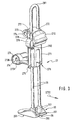
- the fretsaw 10 shown in Fig. 1 consists of a gun-like lower base housing 12 with a cross after Handle protruding below 13. From its exit area the handle 13 is angled backwards from the base housing 12 arranged. The rear contour of the handle 13 forms a concave in the exit area from the housing 12 arched throat 14, horizontally to the rear as the lower outer contour of the base housing 12 is continued. The throat 14 nestles into the operating hand and lies approximately in the middle between your thumb and index finger on or in this clamped. The horizontal one is supported rear area of the base housing 12 on the back of the hand and from the operator's forearm and forms an elongated one Support lever, so that the fretsaw 10 when sawing can be handled in a particularly controlled manner.
- the handle 13 carries one from the front of the handle 13 stepping, nose-like projections 130 closely framed on the sides Switch button 15 to interrupt or close the circuit. From the bottom of the handle 13 comes a power cord 16 for power supply to the inside of the base housing 12 arranged motor, not shown.
- the base housing 12 consists of two longitudinally divided half-shells 1201, 1202 and carries a flat, ship-deck-like top Support surface 18 with longitudinal grooves 20 on the one Workpiece 19 can be supported for processing.
- the base housing 12 carries on both sides below one circumferential outer edge 68 two spaced from each other Tension clips 21, only the two of which are on the left arranged are recognizable.
- a lower arm emerges from the base housing 12 to the rear 221 of a U-shaped bracket 22 made of bent tube exists and tightly encompassed by the half-shells 1201, 1202 becomes.
- the lower arm 221 curves upward in the front an upper arm parallel to the lower arm 221 222 about.
- This upper arm 222 carries on its forward facing free end of an end housing 24 which on the arm 222 Fixing screws 23 (Fig. 7) is fixed and that two longitudinally divided housing shells 240, 241.
- the End housing 24 carries a tension lever accessible from above 25, the handle 127 by a trough or notch-like Recess 242 can be gripped under with the finger of the operating hand and up to open in the direction of the operating arrow 26 is pivotable.
- the end housing 24 carries one at its rounded front end Workpiece hold-down 27, which consists of two round slide bars 28, which is in the end housing 24 relative to the lower Housing 12 are lockable slidably mounted.
- the two Slide rods 28 protrude above and below the end housing 24 and are at the top by a U-shaped arch 281 connected with each other.
- the slide rods 28 carry on her lower free end facing the support surface 18 a foot-like stop 30, which is parallel to the support surface 18 horseshoe-shaped with one back slot 29 open towards the front, in which a jigsaw blade 33, with its row of teeth 32 (Fig. 7) facing forward, laterally and guided from behind or against too far to the side or backward deflection is secured.
- the workpiece hold-down 27 is after depressing it Push button 270 protruding frontally from the end housing its locking position can be moved upwards.
- the jigsaw blade 33 has two clamping ends (FIG. 7), designed as an injected plastic nipple 34 are and the diameter of the saw blade 33 at its clamping ends significantly enlarged so that this in fork-like Abutments 56, 57 can be hooked in and thus tensioned.
- the end housing 24 has at its front area below the Push button 270 a slot-like assembly window 243, through which the clamping end designed as a nipple 34 of the saw blade 33 can be suspended in its upper abutment 56 is.
- the base housing 12 corresponds to this a frontal mounting slot 35 through which the lower Clamping end of the jigsaw 33 in the form of a second Nipples 34 can be attached.
- Fig. 2 shows the fretsaw 10 from the top right with a Saw table 37 coupled, the upper, flat support surface 137 flush in the support surface 18 of the base housing 12 merges, the grooves 20 of the contact surfaces 137, 18th merge regularly.
- the saw table 37 has a front not shown at the bottom of the suction nozzle, the one above in the area the bearing surface 137 opens into a suction hole 39 through which sawdust formed during sawing can be extracted if a suction hose of a vacuum cleaner on the suction nozzle or the like. is connected.
- the saw table 37 has a center in its rear area U-shaped, leading into the bearing surface 137, after continuous recess 40 at the bottom which corresponds to the outer contour or the outer edge 68 of the contact surface 18 of the base housing 12 equivalent.
- the recess 40 carries on top of opposite Longitudinal guides, not shown, which are a bayonet-type Latching the base housing 12 of the Fretsaw 10 in the saw table 37 and its play-free Allow mounting in it.
- a locking button 42 integrated in the support surface 137 forms a detent 43, which corresponds to a Recess 1210 of the base housing 12 near the support surface 18 engages and the base housing 12 and thus the fretsaw 10 releasably holds against the saw table 37.
- the support surface 137 of the saw table 37 is perpendicular to below from screw holes evenly spaced outwards 44 pass through, through which screws can be inserted with which the saw table 37 on a solid base, for example workbench or the like.
- the saw table 37 has at its outer edge at the rear Clamping openings, not shown, on - for the entry of a Clamping jaw of a screw clamp, not shown, with the it can be attached to a solid base.
- the handle 13 protrudes below the saw table 37, so that the fretsaw 10 together with the saw table 37 can be used as a hand tool.
- FIG. 3 shows the workpiece hold-down device 27 as a detail laterally from the right front with two parallel, round slide bars 28, a stop 30 at the bottom at its free end wear.
- the stop 30 has plug domes 301, into which the free Ends of the slide rods 28 are inserted.
- the stop 30 is level with its flat sole 293 to the Slide rods 28 arranged and extends in the feed direction According to directional arrow 2733 U-shaped open to the front.
- the slot formed between the legs 290, 291 encompasses the saw blade 33 laterally and from behind (Fig. 1).
- the sole 293 of the stop foot 30 is made of material that is softer than wood and therefore when supported on one Workpiece 19 (Fig. 1) protects the surface. Furthermore has a gentle effect on the surface that the front ends the leg 290, 291 of the stop foot 30 like a ski tip are slightly curved upwards.
- a holder housing 271 of the workpiece hold-down device 27 Slidably holds captive between the slide rods 28 a holder housing 271 of the workpiece hold-down device 27 firmly that the slide rods 28 with guide slots 275 grips without play and thus guides them precisely along.
- a spring plate 276 pushed, which is captive on the slide rods 28 holds and thereby the holder housing 271 opposite the slide rods 28 locked.
- a push button in the middle of the slide rods 28 270 arranged to compress the legs 2760, 2761 of the U-shaped spring plate 276 is used (Fig. 4).
- the cylindrical end pieces of the mounting arms 273 have central ones Through holes 274 for screws or the like fasteners, the lower mounting arm 273 in addition has an eye 2731 that is axially advanced formed for the through hole 274 concentric edge 2730 the entrance of a cylindrical part of the end housing 24 serves.
- the holder housing 271 is in the end housing 24 positively between its half shells 241, 240 can be inserted or clamped.
- the push button 270 grips the slide rods 28 captively with guide holes 272 and is together with the holder housing 271 slidably mounted on the slide rods 28.
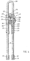
- Fig. 4 shows a longitudinal section of the workpiece hold-down device 27 with the slide rods 28 and with those previously mentioned in FIG. 3 Details that are not fully mentioned again should be.
- the arrangement of the U-shaped spring plate 276 becomes clear in the slot 280 of the holder housing 271 with its lower Leg 2761.
- the lower leg 2761 is fork-shaped slotted (Fig. 6) and thereby forms a slot-like Passage opening 2781 with which he spaced the slide rods 28 embraces.
- the upper leg 2760 of the spring plate 276 engages around one Slide rod 28 with a relatively narrow locking hole 277 and the other slide rod 28 with a slide rod 28 non-contact slide hole 278.
- the locking hole 277 is an elongated hole with a parallel to leg 2760 Longitudinal axis designed and adheres to his outermost edge on the slide rod 28.
- the pushbutton 270 Is supported between the locking hole 277 and the slide hole 278 the pushbutton 270 at the top and bottom of the flat side of the upper leg 2760 with two opposite lugs 279 each linear, from transverse to the thigh axis. If the push button 270 is now pressed towards the stop 30, the upper leg 2760 of the spring plate 276 pivots in the same direction downward. Thereby, the locking hole 277 gives one Slide rod 28 free, so that both slide rods 28 opposite the button 270 and the holder housing 271 pushed up can be.
- push button 270 is pressed with one hand and with the other hand the bow 281 of the slide rods 28 upwards drawn.
- the push button 270 need not be operated because the Slide rods 28 together with the stop 30, the locking hole can happen against the tilt direction and always 270 freely slidable down to the bearing surface 18 are.
- Fig. 5 shows the workpiece hold-down device 27 in a spatial Rear right view as a single assembly, whereby the details of Fig. 3 become clear, especially the U-shaped, horseshoe-shaped design of the stop 30 and - on the holder housing 271 - the cylindrical Design of the end pieces of the mounting arms 273.
- FIG. 6 shows the spring plate 276 spatially as a detail with the upper and lower legs 2760, 2761, the Slide and locking hole 278, 277 and the slot 282.
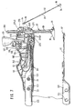
- FIG. 7 shows the front areas of the lower and upper arms 221, 222 of the U-shaped bracket 22 without the base housing 12, only with the left half shell of the End housing 24 and the clamping mechanism 25 for loosening or Attach the jigsaw blade 33.
- the lower arm 221 has a horizontal at its free end Flattened 54 on which a flat leaf spring 51 Attachment points 59 attached, in particular riveted, is.
- the leaf spring 51 carries on as an abutment for the Saw blade clamping the free end 57 a central Fork slot 58 for the passage of the saw blade 33 and for Hold the nipple 34.
- the free end 57 of the lower Leaf spring 51 is at the very end - and at it then to the rear like a roof - angled, so that on the underside of the roof-like bend in A groove 62 is formed in the transverse direction, into which a Cutting edge 61 of the nipple 34 is supported in an articulated manner.
- the free end 57 sits after the roof-like area the lower leaf spring 51 in a short, flat area on which there is an upward curvature 66 with a central longitudinal slot 660 that connects through Stamping or embossing a tab 64 that is curved downward becomes.
- the curvature 66 and the tab 64 together form an oval eyelet 65 for hanging an unillustrated Pleuls that rotate the motor in an up and down motion the lower leaf spring 51 converts.
- the left shell 241 of the End housing 24 attached by means of fastening screws 23.
- the free end of the upper arm 222 is like that of the upper Arms 221 also a horizontal flattening 53, on the other
- the upper leaf spring 50 at the upper side at fastening points 59 fastened in particular is riveted.
- the upper leaf spring 50 extends as open to the right U with her legs 501, 502 outwards - like that free end 53 of the upper arm 222 -, the lower, short Leg 501 is attached to arm 222.
- the legs 501, 502 are connected to one another by a curvature 52.
- the free end 56 of the upper, longer leg 502 of the Leaf spring 50 is angled upwards at the free end and then V-shaped downwards - mirror image to the outer end 57 of the lower leaf spring 51 and also forms a groove 62 therein, which is also by a pass through the middle fork slot 58 beyond its center is so that the saw blade 33 with its other nipple 34th in the fork slot 58 or in the groove 62 of the V-shaped area is articulated, a mirror image of the lower one Clamping end 34 of the saw blade 33.
- the arms 221, 222 carry through holes near their free ends 123, which spanned across the bracket 22 Level and the passage of the fastening screws 23 for fastening the base or end housing 12, 24, especially their half shells, are used.
- the upper leg 502 of the upper leaf spring 50 is a assigned to two-armed lever trained clamping lever 25, the about a pivot axis 125 in the end housing 24 with his Handle 127 can be pivoted upwards so that its cam 126 steps down while doing the upper leg 502 Leaf spring 50 takes to the lower arm 221.
- the handle 127 of the Clamping lever 25 a tubular hollow body which is open to the rear, in which the operator with a finger, guided by a recess 242 in the outer contour of the end housing 24, can intervene comfortably and pivot upwards.
- the clamping lever 25 is with its handle 127 upwards and with its cam 126 swung down and pushes the top one Leg 502 of the leaf spring 50 down.
- the tension lever 25 emerges from the concave recess 242 of the end housing 24, in which he dips flush in the clamping position.
- Locking pin 129 of the housing shell 241 shown in one hollow cylindrical locking opening 128 of the clamping lever 25 when reached the release position can snap into place.
- the assembly window 243 in the end housing 24 or pass through the mounting slot 35 (FIG. 1) in the base housing 12 become.
- the spring plate 276 is tilted on the slide rod 28 of the Workpiece hold-down 27 as soon as a force pushes it up tries to move. This means that the workpiece hold-down 27 the slide rods 28 self-locking in one direction locks. A downward force acts on the slide rods 28 against the tilt direction, the spring plate gives 276 the slide rods 28 free, so that the hold-down 27 free is slidable downwards.
- the push button 270 Only in the event that the workpiece hold-down 27 upwards to be pushed, the push button 270 must be pressed. Do this by depressing the upper leg 2760 of the spring plate 276 the locking hole 277 from the tilted position solved against the slide rod 28 and placed horizontally, so that the slide rod 28 is released and the workpiece hold-down 27 or its Stop 30 can be pushed up.
- the holder housing 271 is a molded plastic part. It encompasses his Guide slots 275 the slide rods 28 and serves as a bearing for the lower leg 2761 of the spring plate 276. As a result, the workpiece hold-down 27 can be pre-assembled be assembled by all the individual parts of the workpiece hold-down device 27 captive so to speak on the slide rods to be threaded.
- the pre-assembled component of the workpiece hold-down 27 is laterally in one of the housing shells 240 open at the top, 241 of the end housing 24 is inserted, the mounting arms 273 with its through holes 274 on domat plug-in receptacles 2740 of the end housing 24 are included and with this are screwable. By engaging the mounting arms 273 into the dome-like projections 2740 of the end housing 24 the position fixation of the workpiece hold-down 27 opposite reached the end housing 24.
Landscapes
- Engineering & Computer Science (AREA)
- Mechanical Engineering (AREA)
- Life Sciences & Earth Sciences (AREA)
- Wood Science & Technology (AREA)
- Forests & Forestry (AREA)
- Sawing (AREA)
Description
Claims (14)
- Handgeführte Laubsägemaschine (10) mit einem Laubsägeblatt (33), das zwischen zwei im wesentlichen parallelen, vorzugsweise aus einem U-förmigen Bügel (22), insbesondere Rohr, gebildeten oberen und unteren Armen (221, 222) an deren Enden lösbar spannbar ist und über einen von der Laubsägemaschine (10) getragenen Motor, insbesondere hin- und hergehend, antreibbar ist, wobei am einem der Arme (221, 222) ein Handgriff (13) angeordnet ist, dadurch gekennzeichnet, daß zwischen den beiden Armen (221, 222) ein stempelartig auf ein zu bearbeitendes Werkstück (19) abstützbarer Werkstückniederhalter (27) einstellbar angeordnet ist, der der Lagesicherung des Werkstücks (19) bei dessen Eintreten zwischen die Arme (221, 222) der Laubsägemaschine (10) bei deren Vorschub dient.
- Laubsäge nach Anspruch 1, dadurch gekennzeichnet, daß der Werkstückniederhalter (27) einen fußartigen Anschlag (30) zum Abstützen auf dem Werkstück (19) hat, der an mindestens einer Gleitstange (28), insbesondere an deren freien Ende, angeordnet ist, wobei die Gleitstange (28) als Fingerschutz gegenüber der Verzahnung des Laubsägeblatts (33) dient.
- Laubsäge nach Anspruch 2, dadurch gekennzeichnet, daß der Werkstückniederhalter (27) zwei parallele Gleitstangen (28) hat, die, insbesondere aus einem Stück bestehend, durch einen U-förmigen Bogen (281) miteinander verbunden sind.
- Laubsäge nach Anspruch 3, dadurch gekennzeichnet, daß der insbesondere aus Kunststoff bestehende, Anschlag (30), vorzugsweise über Steckdome (301), mit den, vorzugsweise aus Stahl bestehenden, Gleitstangen (28), insbesondere mit deren freien Enden, zusammensteckbar ist.
- Laubsäge nach Anspruch 1, dadurch gekennzeichnet, daß der Anschlag (30) das Laubsägeblatt (33), vorzugweise mit den Rändern eines Schlitzes (29), seitlich und hinten umgreift und dessen Auslenkungsbegrenzung nach hinten dient.
- Laubsäge nach Anspruch 5, dadurch gekennzeichnet, daß der Werkstückniederhalter (27) ein Haltergehäuse (271) aufweist, das an einem der Arme (221, 222) befestigbar ist.
- Laubsäge nach Anspruch 6, dadurch gekennzeichnet, daß der obere Arm (222) ein, insbesondere Spannmitteln (25) zum lösbaren Spannen des Laubsägeblatts (33) umgreifendes, Endgehäuse (24) trägt, das das Haltergehäuse (271) aufnimmt.
- Laubsäge nach Anspruch 7, dadurch gekennzeichnet, daß das Haltergehäuse (271) die Gleitstangen (28), insbesondere in Führungsschlitzen (275), verschiebbar aufnimmt und Haltearme (273) insbesondere mit Schrauben-Durchtrittsbohrungen (274), aufweist, die gegenüber dem Endgehäuse (24) formschlüssig festlegbar sind.
- Laubsäge nach Anspruch 8, dadurch gekennzeichnet, daß das Haltergehäuse (271) ein quer zu den Gleitstangen (28) angeordnetes, u-förmig gebogenes Federblech (276) trägt, das die Gleitstangen (28) im Ruhezustand festhält und durch Zusammendrücken der U-Schenkel diese zumindest in eine Schieberichtung freigibt.
- Laubsäge nach Anspruch 9, dadurch gekennzeichnet, daß das Federblech (276) in einem Einsteckschlitz (280) am Haltergehäuse (271) festlegbar ist und sich an den Gleitstangen (28) unverlierbar festhält, indem es mindestens eine dieser mit einer Arretierbohrung (277), vorzugsweise die andere der Gleitstangen (28) mit einer Gleitbohrung (278), umgreift.
- Laubsäge nach Anspruch 10, dadurch gekennzeichnet, daß die U-Schenkel des Federblechs (276) mittels einer Druckaste (270) zusammenpreßbar sind, wobei sich die Drucktaste (270) mit Führungsbohrungen (272) an den Gleitstangen (28) unverlierbar, verschiebbar festhält.
- Laubsäge nach Anspruch 11, dadurch gekennzeichnet, daß sich die Druckaste (270) oben und unten an den Flachseiten des oberen Schenkels (2761) des Federblechs (276) mit je einer Nase (279) punkt- oder linienförmig zwischen der Gleit- (278) und der Arretierbohrung (277) abstützt.
- Laubsäge nach Anspruch 10, dadurch gekennzeichnet, daß der Bogen (281) als Handgriff zum Verstellen des Werkstückniederhalters (27) dient.
- Laubsäge nach einem der vorhergehenden Ansprüche, dadurch gekennzeichnet, daß die Laubsäge (10) an einem Basisgehäuse (12) oben eine, insbesondere mit Rillen strukturierte, vorzugsweise zum unteren Arm (221) fluchtende, ebene Auflagefläche (18) zum Abstützen des Werkstücks (19) trägt, gegenüber der der Niederhalter (27), insbesondere der Anschlag (30), verschiebbar ist.
Applications Claiming Priority (2)
| Application Number | Priority Date | Filing Date | Title |
|---|---|---|---|
| DE19925746A DE19925746A1 (de) | 1999-06-05 | 1999-06-05 | Handgeführte Laubsägemaschine |
| DE19925746 | 1999-06-05 |
Publications (2)
| Publication Number | Publication Date |
|---|---|
| EP1059151A1 EP1059151A1 (de) | 2000-12-13 |
| EP1059151B1 true EP1059151B1 (de) | 2004-08-04 |
Family
ID=7910324
Family Applications (1)
| Application Number | Title | Priority Date | Filing Date |
|---|---|---|---|
| EP00109533A Expired - Lifetime EP1059151B1 (de) | 1999-06-05 | 2000-05-04 | Handgeführte Laubsägemaschine mit Auflagefläche und Werkstückniederhalter |
Country Status (3)
| Country | Link |
|---|---|
| EP (1) | EP1059151B1 (de) |
| JP (1) | JP2000355001A (de) |
| DE (2) | DE19925746A1 (de) |
Families Citing this family (2)
| Publication number | Priority date | Publication date | Assignee | Title |
|---|---|---|---|---|
| US8438741B2 (en) | 2011-08-05 | 2013-05-14 | Black & Decker, Inc. | Lock for power tool |
| CN108816653B (zh) * | 2018-07-18 | 2021-03-12 | 安徽瑞祥工业有限公司 | 一种涂胶机器人的涂胶枪定位机构 |
Family Cites Families (2)
| Publication number | Priority date | Publication date | Assignee | Title |
|---|---|---|---|---|
| US2753898A (en) * | 1950-05-03 | 1956-07-10 | Allison M Macfarland | Electromagnetically operated hand tool |
| US5176059A (en) * | 1991-08-09 | 1993-01-05 | Skil Corporation | Scroll saw hold down apparatus providing enhanced work piece clearance |
-
1999
- 1999-06-05 DE DE19925746A patent/DE19925746A1/de not_active Withdrawn
-
2000
- 2000-05-04 DE DE50007253T patent/DE50007253D1/de not_active Expired - Lifetime
- 2000-05-04 EP EP00109533A patent/EP1059151B1/de not_active Expired - Lifetime
- 2000-06-05 JP JP2000167862A patent/JP2000355001A/ja active Pending
Also Published As
| Publication number | Publication date |
|---|---|
| EP1059151A1 (de) | 2000-12-13 |
| DE19925746A1 (de) | 2000-12-07 |
| DE50007253D1 (de) | 2004-09-09 |
| JP2000355001A (ja) | 2000-12-26 |
Similar Documents
| Publication | Publication Date | Title |
|---|---|---|
| DE4306974B4 (de) | Kraftgetriebene Schwertsäge | |
| EP0157005A2 (de) | Führungsvorrichtung für eine Handwerkzeugmaschine | |
| EP3256297B1 (de) | Hand-trennmaschine mit einer tiefeneinstelleinrichtung | |
| WO2019029998A1 (de) | Hand-werkzeugmaschine mit einem absauganschluss | |
| EP0986448A1 (de) | Elektrische handwerkzeugmaschine | |
| DE202006005165U1 (de) | Schneideanordnung für eine Haarschneidemaschine | |
| EP1102663B1 (de) | Handgeführte laubsägemaschine mit auflagefläche die lösbar an einen sägetisch anclipsbar ist | |
| EP1059151B1 (de) | Handgeführte Laubsägemaschine mit Auflagefläche und Werkstückniederhalter | |
| EP1102664B1 (de) | Handgeführte laubsägemaschine | |
| EP1152874B1 (de) | Handgeführte laubsägemaschine mit pistolenartigem, unterarmstützendem basisgehäuse | |
| WO2003103902A1 (de) | Handhobelmaschine | |
| EP3246141B1 (de) | Werkzeugmaschine; insbesondere kappsäge | |
| DE19925745A1 (de) | Handgeführte Laubsägemaschine | |
| EP1466690A1 (de) | Säbelsäge mit Justiervorrichtung für eine Führungsvorrichtung | |
| EP1066905B1 (de) | Stichsäge mit Sägeblattführungvorrichtung | |
| DE102021215109A1 (de) | Stichsäge mit Befestigungselement für Absaugstutzen | |
| DE102021215115A1 (de) | Zangenführung für eine Stichsäge | |
| DE102021215114A1 (de) | Stichsäge mit Zangenführungseinheit | |
| DE102021215131A1 (de) | Stichsäge mit zwischen Absaugkanälen aufgenommener Zangenführungseinheit | |
| DE102021215110A1 (de) | Stichsäge mit Pendelhubeinstellmittel | |
| DE102021215108A1 (de) | Stichsäge mit beabstandeten Verbindungsbereichen | |
| DE102021215130A1 (de) | Stichsäge mit Ausblasöffnung | |
| DE102021215113A1 (de) | Stichsäge mit Funktionsschnittstelle | |
| DE102021215111A1 (de) | Stichsäge mit Stützelement | |
| EP4457045A1 (de) | Stichsäge mit beabstandeten verbindungsbereichen |
Legal Events
| Date | Code | Title | Description |
|---|---|---|---|
| PUAI | Public reference made under article 153(3) epc to a published international application that has entered the european phase |
Free format text: ORIGINAL CODE: 0009012 |
|
| AK | Designated contracting states |
Kind code of ref document: A1 Designated state(s): CH DE GB LI |
|
| AX | Request for extension of the european patent |
Free format text: AL;LT;LV;MK;RO;SI |
|
| 17P | Request for examination filed |
Effective date: 20010613 |
|
| AKX | Designation fees paid |
Free format text: CH DE GB LI |
|
| GRAP | Despatch of communication of intention to grant a patent |
Free format text: ORIGINAL CODE: EPIDOSNIGR1 |
|
| GRAS | Grant fee paid |
Free format text: ORIGINAL CODE: EPIDOSNIGR3 |
|
| GRAA | (expected) grant |
Free format text: ORIGINAL CODE: 0009210 |
|
| AK | Designated contracting states |
Kind code of ref document: B1 Designated state(s): CH DE GB LI |
|
| REG | Reference to a national code |
Ref country code: GB Ref legal event code: FG4D Free format text: NOT ENGLISH |
|
| REG | Reference to a national code |
Ref country code: CH Ref legal event code: EP Ref country code: CH Ref legal event code: NV Representative=s name: SCINTILLA AG, DIREKTION |
|
| REF | Corresponds to: |
Ref document number: 50007253 Country of ref document: DE Date of ref document: 20040909 Kind code of ref document: P |
|
| GBT | Gb: translation of ep patent filed (gb section 77(6)(a)/1977) |
Effective date: 20041216 |
|
| PG25 | Lapsed in a contracting state [announced via postgrant information from national office to epo] |
Ref country code: LI Free format text: LAPSE BECAUSE OF NON-PAYMENT OF DUE FEES Effective date: 20050531 Ref country code: CH Free format text: LAPSE BECAUSE OF NON-PAYMENT OF DUE FEES Effective date: 20050531 |
|
| PLBE | No opposition filed within time limit |
Free format text: ORIGINAL CODE: 0009261 |
|
| STAA | Information on the status of an ep patent application or granted ep patent |
Free format text: STATUS: NO OPPOSITION FILED WITHIN TIME LIMIT |
|
| 26N | No opposition filed |
Effective date: 20050506 |
|
| REG | Reference to a national code |
Ref country code: CH Ref legal event code: PL |
|
| PGFP | Annual fee paid to national office [announced via postgrant information from national office to epo] |
Ref country code: GB Payment date: 20090528 Year of fee payment: 10 |
|
| GBPC | Gb: european patent ceased through non-payment of renewal fee |
Effective date: 20100504 |
|
| PG25 | Lapsed in a contracting state [announced via postgrant information from national office to epo] |
Ref country code: GB Free format text: LAPSE BECAUSE OF NON-PAYMENT OF DUE FEES Effective date: 20100504 |
|
| PGFP | Annual fee paid to national office [announced via postgrant information from national office to epo] |
Ref country code: DE Payment date: 20130723 Year of fee payment: 14 |
|
| REG | Reference to a national code |
Ref country code: DE Ref legal event code: R119 Ref document number: 50007253 Country of ref document: DE |
|
| REG | Reference to a national code |
Ref country code: DE Ref legal event code: R119 Ref document number: 50007253 Country of ref document: DE Effective date: 20141202 |
|
| PG25 | Lapsed in a contracting state [announced via postgrant information from national office to epo] |
Ref country code: DE Free format text: LAPSE BECAUSE OF NON-PAYMENT OF DUE FEES Effective date: 20141202 |