EP1059228A1 - Tauklemmer - Google Patents
Tauklemmer Download PDFInfo
- Publication number
- EP1059228A1 EP1059228A1 EP00420115A EP00420115A EP1059228A1 EP 1059228 A1 EP1059228 A1 EP 1059228A1 EP 00420115 A EP00420115 A EP 00420115A EP 00420115 A EP00420115 A EP 00420115A EP 1059228 A1 EP1059228 A1 EP 1059228A1
- Authority
- EP
- European Patent Office
- Prior art keywords
- rope
- clamping member
- drum
- tension
- lever
- Prior art date
- Legal status (The legal status is an assumption and is not a legal conclusion. Google has not performed a legal analysis and makes no representation as to the accuracy of the status listed.)
- Withdrawn
Links
- 238000011144 upstream manufacturing Methods 0.000 claims description 34
- 230000000903 blocking effect Effects 0.000 claims description 12
- 238000006073 displacement reaction Methods 0.000 claims description 11
- 238000004804 winding Methods 0.000 claims description 6
- 230000002093 peripheral effect Effects 0.000 claims description 4
- 230000036961 partial effect Effects 0.000 claims description 3
- 210000000056 organ Anatomy 0.000 description 9
- 241001417494 Sciaenidae Species 0.000 description 6
- 239000000835 fiber Substances 0.000 description 4
- 210000002445 nipple Anatomy 0.000 description 4
- 230000002829 reductive effect Effects 0.000 description 4
- 241001080024 Telles Species 0.000 description 2
- 238000013270 controlled release Methods 0.000 description 2
- 235000020004 porter Nutrition 0.000 description 2
- 238000012550 audit Methods 0.000 description 1
- 239000000470 constituent Substances 0.000 description 1
- 230000000694 effects Effects 0.000 description 1
- 230000000670 limiting effect Effects 0.000 description 1
- 238000000034 method Methods 0.000 description 1
- 230000000284 resting effect Effects 0.000 description 1
- 230000002441 reversible effect Effects 0.000 description 1
Images




Classifications
-
- B—PERFORMING OPERATIONS; TRANSPORTING
- B63—SHIPS OR OTHER WATERBORNE VESSELS; RELATED EQUIPMENT
- B63B—SHIPS OR OTHER WATERBORNE VESSELS; EQUIPMENT FOR SHIPPING
- B63B21/00—Tying-up; Shifting, towing, or pushing equipment; Anchoring
- B63B21/04—Fastening or guiding equipment for chains, ropes, hawsers, or the like
- B63B21/08—Clamping devices
-
- F—MECHANICAL ENGINEERING; LIGHTING; HEATING; WEAPONS; BLASTING
- F16—ENGINEERING ELEMENTS AND UNITS; GENERAL MEASURES FOR PRODUCING AND MAINTAINING EFFECTIVE FUNCTIONING OF MACHINES OR INSTALLATIONS; THERMAL INSULATION IN GENERAL
- F16G—BELTS, CABLES, OR ROPES, PREDOMINANTLY USED FOR DRIVING PURPOSES; CHAINS; FITTINGS PREDOMINANTLY USED THEREFOR
- F16G11/00—Means for fastening cables or ropes to one another or to other objects; Caps or sleeves for fixing on cables or ropes
- F16G11/10—Quick-acting fastenings; Clamps holding in one direction only
- F16G11/105—Clamps holding in one direction only
- F16G11/106—Clamps holding in one direction only using a toothed surface
Definitions
- the present invention relates to a device for blocking rope allowing, in a locked state, to block a rope undergoing a voltage upstream of the device and, in a state of unlocking, to release this rope.
- upstream defines the side of the rope connected to the object to be tensioned with this rope
- downstream defines the opposite side
- This device is in particular intended to be used on sailing pleasure boats, to block various ropes that understand the rigging of these boats, including the halyards, but this application is not limiting.
- the term “upstream” then defines, in in the case of a halyard, the side of the rope connected to the sail, and the term “downstream” defines the side by which the halyard is intended to be maneuvered by means of a capstan.
- An existing device generally called “cleat”
- cleat includes two pivoting cams, one of which is pivoted towards each other and each having a curved lateral portion on its side facing the other cam.
- the rope is engaged between these cams, at against the restoring force acting on them, and the tension that it undergoes upstream causes the cams to pivot in the direction of tightening of the rope by the latter.
- a device of this type has certain drawbacks, especially with regard to its limited resistance to tensions important, the difficulty of dropping the rope in the event of such tension, the need to reintroduce the rope between the cams after each dropping, and the significant wear and tear generated on the rope by tightening the cams.
- cam Another type of device, generally referred to as a cam ", includes a frame crossed by the rope and a cam eccentric mobile in pivoting in this frame. Cam can be moved between a locking position, in which it clamps the rope between it and the bottom of the frame, and an unlocking position, in which it is located at a distance from the rope and therefore does not obstruct the sliding thereof through the device.
- This type of device has a higher resistance than cleats previously described but retains a lot disadvantages of these.
- the operation of the cam can be made very difficult, if not impossible, in the event of significant stress on the rope, which requires exerting a tension on this rope downstream of the device to balance the upstream voltage and thus release the rope.
- the exercise of this downstream tension involves a maneuver additional, preventing rapid release of the rope in some emergency circumstances.
- the wear and tear generated on the rope by this type of device is important, and the tightening produced is not very effective with some high strength fibers, which have a low coefficient of friction.
- a third type of existing device includes a frame containing a series of plates, these plates being tiltable and pierced with holes. The rope is engaged through these holes and the the stress it experiences causes the pads to tilt. This tilt allows the pads to press strongly against the rope, which ensures the jamming of the latter.
- a rope blocking device comprising a first and a second rope tightening member, between which this rope is engaged.
- Said first clamping member is pivotally mounted relative to the device and includes a circular surface around which the rope can be engaged, and said second clamping member is disposed by report to said first clamping member so as to allow said tightening the rope between it and said first tightening member.
- At least one of these members is movable between a locking position, in which he tightens the cord between him and the other organ, and a position of unlocking, in which it does not exert said tightening in order to authorize the scrolling of the rope through the device.
- the present invention aims precisely to remedy these fundamental disadvantages of devices of this type, providing a rope blocking device which allows both easy release and fast rope in all circumstances, without requiring the exercise of a rope tension downstream of the device, perfect blocking of a rope made of fibers with a low coefficient of friction, and reduced wear on the rope.
- the device that the invention relates to comprises a first and a second rope tightening member as known by documents DE 1,231 and FR 2,753,169 cited above.
- the winding of the rope on said first clamping member largely reduces the residual stress on the rope at the second clamping member.
- the tightening exerted by the latter can therefore be reduced accordingly, which limits wear generated on the rope as well as the forces undergone by said organs at level of this tightening.
- the operation of the organ or organs of movable tightening, in order to release the rope is easy, which eliminates the need to tension the line downstream of the device to facilitate, or to achieve, this release.
- the winding above mentioned of the rope allows a large contact surface of this rope and of said first clamping member, thus generating significant friction, which increase with the tension on the rope.
- Such a device prevents any risk of uncontrolled dropping of the rope during its maneuver.
- the second clamping member is movable and is constituted by a cam pivoting, this cam being able to pivot in one direction to engage with the rope, when the upstream tension is higher than the downstream tension, and in the opposite direction to release the rope, when the tension exerted downstream is at least equal to the tension exerted upstream.
- said first clamping member is movable towards the second member tightening when the upstream voltage is greater than the downstream voltage, and is movable in the opposite direction to this second clamping member when the tension exerted downstream is at least equal to the tension exerted upstream.
- the first clamping member can be a transverse cylinder or may consist of a drum mounted to rotate on an axis.
- the scrolling of the rope through the device is facilitated by the rotation of the drum, which allows rapid maneuvering of release of the rope.
- the device comprises means releasable to block the rotation of the drum in the corresponding direction the exercise of an upstream voltage greater than the downstream voltage; these means may in particular be constituted by a ratchet system connected to the device and corresponding notches arranged on the drum.
- the rope In said intermediate unlocking position, the rope can scroll by sliding around the drum, without rotation of the latter, so with friction, which corresponds to a controlled release of the rope.
- said fully unlocked position the rotation of the drum is released, so that this drum is driven by the scrolling of the cordage, which corresponds to a rapid release of this cordage.
- the second clamping member comprises, at a distance from its clamping zone intended to come into contact with the rope, a first cylindrical part, parallel to the axis of the drum, forming said pawl, and, on the side of this zone clamping, a second cylindrical part, also parallel to said axis; this second cylindrical part is engaged, with the possibility of pivoting and sliding, in a light; this light is oriented so that the displacement of said second part cylindrical in it rotates the second clamping member, around the axis of said first cylindrical part, towards its locking position, when this second clamping member is driven in displacement curvilinear by the drum, by means of said first part cylindrical in engagement with one of the notches of the drum, following the exercise on the stringing an upstream voltage greater than the downstream voltage.
- the pawl is thus arranged directly on the second member tightening, and said light allows a slight curvilinear movement of this second clamping member when the upstream voltage greater than the downstream tension causes the drum to rotate. This curvilinear displacement, by the orientation of the light, allows to move the second organ of tightening towards this drum, until tightening of the rope.
- the light In the lever locked position, the light allows the automatic movement of the second clamping member, as indicated previously.
- the pivoting of the lever towards said position of intermediate release allows the same light to be moved to distance from the drum and therefore move the second organ clamping to its unlocking position; this movement takes place however without releasing the pawl which constitutes said first part cylindrical outside the corresponding notch of the drum, due to the cooperation of said second cylindrical part with said surface of cam. Pivoting the lever to the fully unlocked position causes the pawl to disengage from the notch of the drum.
- the first clamping member comprises ribs projecting radially outward from its peripheral face exterior, these ribs making it possible to increase the friction between the rope and this first clamping member.
- the second clamping member is formed by the assembly of two parts, one of which comprises said first and second cylindrical parts and the other of which comprises said zone of tightening the rope, means being provided to allow placing one of these parts relative to the other in several positions longitudinal and to maintain these parts in a determined position.
- the hub of the drum comprises an axial cavity having a non-circular profile, which opens onto the outside of the device, this cavity being able to receive means for allowing to manually rotate this drum in order to achieve a bet in total or partial tension of the rope.
- These means can in particular include a ratchet system, such as a needle ratchet system, and a drive crank, in particular a capstan crank.
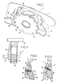
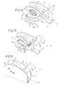
- Figures 1 to 8 show from different angles a device 1 rope blocker allowing, in a locked state, to block a rope under tension upstream of the device and, in an unlocked state, release this rope.
- This device 1 comprises a frame 2, a drum 3 mounted pivoting on this frame 2, a cam 4 for tightening the rope 5 engaged around drum 3, a hairpin spring 6 and a lever 7 pivotally mounted on the frame 2.
- This frame 2 includes a bottom 10 intended to be bolted to a wall, in particular the deck of a sailboat, and two side cheeks 11.
- These cheeks 11 include, arranged opposite one another, holes 12, 13 for the passage of the parts forming the pivot axes of the drum 3 and lever 7, and two lights 14.
- One of the edges 11a of the cheeks 11 which delimit these lights 14 has a curved shape, the reason for which will be explained later.
- the drum 3 comprises a hub 15 and two flanges 16.
- the hub 15 delimits an axial cavity 17 receiving the cylindrical part (not shown) forming its pivot, and the outer peripheral face of this hub 15 has ribs 18 projecting radially towards the outside, shaped to create friction with the rope 5.
- the flanges 16 have notches 19 arranged in their edge peripheral, shaped to cooperate with a pawl described below, so to block the rotation of the drum 3 in the direction of rotation of the needles of a watch, in the example shown, this direction of rotation corresponding to the exercise on line 5 of a tension upstream of the device 1 greater than the voltage exerted downstream of this same device.
- the clamping cam 4 extends along one side of the drum 3, and includes an area 4a for tightening the rope 5. This area 4a is located beyond a winding arc of this rope 5 on this drum 3 which corresponds to an angle of more than 270 °.
- the cam 4 is formed by the assembly of two parts 20, 21, more particularly shown in Figures 3 to 5.
- the part 20 located radially on the outside of this cam 4 relative to the drum 3 has a curved and elongated shape. It includes, at one end, a first cylindrical part 22 and, at its other end, a second cylindrical part 23 formed by two coaxial lateral pins. These two cylindrical parts 22, 23 are parallel to the pivot axis of the drum 3.
- part 22 is intended to cooperate with the notches 19 of the drum 3 and undergoes the action of the spring 6, which urges it radially inward of the drum 3.
- the cam 4 constitutes thus the aforementioned pawl.
- the nipples of part 23 are engaged in the slots 14, the stud located on the side of the lever 7 being further engaged, with possibility of pivoting and sliding, through a light 25 arranged in this lever 7, described below.
- the part 20 further comprises, in its central part and on its internal face, a series of cross-sectional ribs and grooves triangular, and has a light 26 arranged longitudinally at through it, in a direction perpendicular to the axes of the parts 22 and 23.
- This light 26 has, on the outside of the part 20, a width such that it can slide the head of the screw 30 described below, and, on the inside of the part 20, a width less than that of this head but greater than that of the body of this same screw 30, so that it can receive this sliding body.
- the part 21 located radially inward relative to the drum 3 has a width which increases towards one of its longitudinal ends, the widest part of this part 21 constituting said clamping zone 4a.
- this part 21 On its radially outer side, this part 21 comprises a series of ribs and transverse grooves of triangular section, suitable for engagement, respectively, with the ribs and grooves above from part 20, to define a plurality of possible positions of the part 21 relative to the part 20.
- the part 21 also has a tapped hole, which opens in its radially external face, this hole being able to receive said screw 30 engaged through the light 26.
- This screw 30 makes it possible to fix pieces 20 and 21 relative to each other in a position determined relative, most appropriate according to the diameter of the rope 5 to block.
- the part 21 includes notches 27 arranged at the level of zone 4a, in its edge facing the drum 3, to take support against this rope 5.
- the spring 6 is of the "pin" type. Its central winding is engaged on the base of the stud of the part 23 which passes through the lumen 25; one of its lateral branches bears against the part 28 forming the pivot of the lever 7 while its other lateral branch is bent on the side of its free end and is engaged around the cam 4.
- the lever 7 is pivotally mounted on the frame 2 between the positions shown in Figures 6 to 8, corresponding respectively to the positions aforementioned locking, intermediate unlocking and total unlocking of the device 1.
- the lever 7 comprises, in addition to the aforementioned slot 25, a hole 29 receiving the part 28 forming its pivot, and a lug 35 projecting from its face facing the cam 4.
- the length of this lug 35 is such that it can come to bear, from said unlocking position intermediate and to the fully unlocked position, against the cam 4.
- the lever 7 is then placed in the intermediate position shown in FIG. 7, in which the lug 35 no longer lifts the cam 4, so that the part 22 is brought to the level of the notches 19 under the action of the spring 6.
- the light 25 remains distant from the drum 3 and maintains the part 23, therefore zone 4a, at a distance from this drum 3.
- the lever 7 is then moved to the position shown in the figure 6. During this movement, the part 23 slides along the rounded edges 11a of the cheeks 11, which ensures that the part 22 remains in engagement with the notch 19 corresponding, and the cam 4 is brought by the light 25 in a position of contact with the rope 5, by pivoting around the axis from part 22.
- the tension exerted downstream is released when the lever 7 found in the position shown in Figure 6. Due to the friction of the rope 5 on the ribs 18, the tension exerted upstream on the rope 5 tends to rotate the drum 3 clockwise. The drum 3 then tends, through the part 22 engaged with one of the notches 19, to drive the cam 4 in curvilinear movement in the same direction of pivoting.
- the light 25 is in this position of the lever 7, oriented obliquely to the drum 3, the axis longitudinal of this light 25 forming an angle of about 30 ° with the bottom 10 of the frame 2. It then results from the aforementioned stress on the cam 4 in curvilinear displacement and sliding of part 23 in the light 25 thus oriented, that the cam 4 is pressed towards a position of locking, in which its notches 27 bite into the line 5 and immobilize it.
- FIG. 9 shows that, as a variant, the cavity 17, as well as the part 41 of the part 40 forming the pivot of the drum 3 which is intended for be engaged in this cavity 17, can be arranged so as to form a system, known per se, of needle ratchet 42.
- Part 40 further comprises a cavity 43 opening onto the outside of the frame 2, suitable for receiving a capstan crank.
- the rope 5 can thus be tensioned by driving the drum 3 directly by means of this crank.
- Figure 10 shows a very schematic embodiment and simplified device 1.
- the device 1 comprises a cylindrical part 3 around which the rope 5 is wound over several turns, this piece 3 being pivotally mounted by one end around a pivot 45 of axis perpendicular to that of this piece 3 and the rope 5.
- An upstream tension greater than a downstream voltage rotates the part 3 around this pivot 45 and presses turns of rope 5 against a neighboring piece 4, thus achieving a tightening of said turns.
- a pivoting cam 46 makes it possible to separate the piece 3 of piece 4 to release the sliding of the rope 5.
- the device 1 shown in Figures 14 to 17 includes a system composed of two pivoting pawls 60, a hub 61, and a internal toothing forming notches 62, which is arranged in the drum 3.
- the pawls 60 have rounded parts, which are engaged and can rotate in corresponding notches arranged in the hub 61, and rectilinear lateral parts, which can cooperate with the notches 62.
- These pawls 60 have axial pins 63 engaged through a notch 64 and a slot 65 which are arranged in a radial arm 66, this arm 66 being mounted on the hub 61, coaxial therewith.
- the arm 66 is connected by a finger transverse 67 to a similar arm 66 located on the other side of the drum 3.
- the nipples 63 are also engaged through lights 68 fitted in one of the cheeks 11.
- a clamping cam 4 is mounted pivoting on the frame 2, below the drum 3, this cam 4 resting against finger 67 and comprising a surface 69 for tightening the rope 5 between it and this drum 3.
- the invention thus provides a device 1 rope blocker 5 which overcomes the disadvantages of homologous devices of the technique anterior, since this device allows both quick and easy release rope 5 in all circumstances, without requiring the exercise of a rope tension 5 downstream of the device, perfect blocking of a rope 5 made of fibers with low coefficient of friction, and reduced wear on the rope 5.
- rope 5 can be wound on only a fraction of a turn, this fraction corresponding however at least at an angle of more than 180 °, in which case the drum can be replaced by a simple sheave;
- the device can be attached to a wall by the bottom 10 above or may include holes in one or the other of the cheeks 11 for fixing by this cheek;
- the lights 14 can be replaced by a wall projecting from the internal face of the cheek 11, which is shaped to delimit said cam surface 11a;
- the lever 7 can be constituted by a single flange, as shown in the drawing or by two flanges each of which is located along one of said cheeks 11, each of these flanges then comprising a light 25 and a cam surface 11a, each stud 23 being engaged in this slot 25 and coming to cooperate with this surface 11a;
- spring 6 could be any other type, in particular helical; .
Landscapes
- Engineering & Computer Science (AREA)
- General Engineering & Computer Science (AREA)
- Mechanical Engineering (AREA)
- Chemical & Material Sciences (AREA)
- Combustion & Propulsion (AREA)
- Ocean & Marine Engineering (AREA)
- Emergency Lowering Means (AREA)
- Devices For Conveying Motion By Means Of Endless Flexible Members (AREA)
Applications Claiming Priority (2)
| Application Number | Priority Date | Filing Date | Title |
|---|---|---|---|
| FR9907367 | 1999-06-07 | ||
| FR9907367A FR2794447B1 (fr) | 1999-06-07 | 1999-06-07 | Dispositif bloqueur de cordage |
Publications (1)
| Publication Number | Publication Date |
|---|---|
| EP1059228A1 true EP1059228A1 (de) | 2000-12-13 |
Family
ID=9546640
Family Applications (1)
| Application Number | Title | Priority Date | Filing Date |
|---|---|---|---|
| EP00420115A Withdrawn EP1059228A1 (de) | 1999-06-07 | 2000-06-06 | Tauklemmer |
Country Status (3)
| Country | Link |
|---|---|
| US (1) | US6343561B1 (de) |
| EP (1) | EP1059228A1 (de) |
| FR (1) | FR2794447B1 (de) |
Families Citing this family (2)
| Publication number | Priority date | Publication date | Assignee | Title |
|---|---|---|---|---|
| FR2846935A1 (fr) * | 2002-11-13 | 2004-05-14 | Wichard | Dispositif de guidage et de blocage d'un cordage utilisable notamment a bord d'un voilier |
| FR3149860A1 (fr) * | 2023-05-17 | 2024-12-20 | Franck Gressier | Système de réglage de tension pour cordage applicable aux pieds de mat de planche à voile. |
Citations (2)
| Publication number | Priority date | Publication date | Assignee | Title |
|---|---|---|---|---|
| DE1231C (de) | 1877-11-17 | 1900-01-01 | C. KESSELER, Civilingenie.ur, und H. PROTZ in Berlin | Tauklemmer |
| FR2753169A1 (fr) | 1996-09-10 | 1998-03-13 | Lacan Guy Henri | Bloqueur de cordage a faible effort d'ouverture |
Family Cites Families (4)
| Publication number | Priority date | Publication date | Assignee | Title |
|---|---|---|---|---|
| US1692640A (en) * | 1928-04-21 | 1928-11-20 | Erick G Erickson | Anchor-cable guide and holder for boats |
| US3186372A (en) * | 1963-12-20 | 1965-06-01 | Sweetco Inc | Sheet cleat |
| US4465011A (en) * | 1982-07-19 | 1984-08-14 | Schaefer Marine, Inc. | Halyard stopper |
| FR2753159B1 (fr) | 1996-09-10 | 1999-03-26 | Ampafrance | Dispositif d'accrochage d'une nacelle sur une poussette pour enfant, poussette et support equipes d'un tel dispositif |
-
1999
- 1999-06-07 FR FR9907367A patent/FR2794447B1/fr not_active Expired - Fee Related
-
2000
- 2000-05-23 US US09/576,213 patent/US6343561B1/en not_active Expired - Fee Related
- 2000-06-06 EP EP00420115A patent/EP1059228A1/de not_active Withdrawn
Patent Citations (2)
| Publication number | Priority date | Publication date | Assignee | Title |
|---|---|---|---|---|
| DE1231C (de) | 1877-11-17 | 1900-01-01 | C. KESSELER, Civilingenie.ur, und H. PROTZ in Berlin | Tauklemmer |
| FR2753169A1 (fr) | 1996-09-10 | 1998-03-13 | Lacan Guy Henri | Bloqueur de cordage a faible effort d'ouverture |
Also Published As
| Publication number | Publication date |
|---|---|
| FR2794447B1 (fr) | 2001-07-06 |
| FR2794447A1 (fr) | 2000-12-08 |
| US6343561B1 (en) | 2002-02-05 |
Similar Documents
| Publication | Publication Date | Title |
|---|---|---|
| EP0008560B1 (de) | Vorsegelroller mit Reffeinrichtung | |
| FR2561878A1 (fr) | Dispositif de fermeture, en particulier pour des chaussures de ski a ouverture arriere | |
| EP2576414B1 (de) | Vorrichtung zum ergreifen und einstellen der spannung eines länglichen elements wie eines kabels, seils oder dergleichen | |
| EP0779951A1 (de) | Fernbedienbarer karabinerhaken, zum festmachen eines taues | |
| FR2753169A1 (fr) | Bloqueur de cordage a faible effort d'ouverture | |
| FR2794447A1 (fr) | Dispositif bloqueur de cordage | |
| FR2710238A1 (fr) | Moulinet de pêche à dispositif de tension de fil . | |
| FR2550694A1 (fr) | Tendeur de sangle avec verrou | |
| FR2475514A1 (fr) | Treuil de pont de bateau, a entrainement manuel | |
| FR2763478A1 (fr) | Dispositif de blocage deblocable de fil sur bobine de moulinet de peche | |
| EP1281343A1 (de) | Rollenhalterflansch zur Vermeidung von Schleifenbildung in einem Aufwischmaterialspender | |
| FR3001517A1 (fr) | Bloqueur de cordage. | |
| EP0391805A1 (de) | Selbsthaltende Winde mit gelenkig angeordneten Zähnen | |
| BE1015994A5 (fr) | Enrouleur de sangles. | |
| EP1319586A1 (de) | Unterbodenbefestigung für ein Kraftfahrzeugersatzrad | |
| FR2813299A1 (fr) | Treuil pour une roue de secours d'un vehicule | |
| EP0052044A1 (de) | Tauklemmer | |
| CH650752A5 (en) | Manual clamping device | |
| FR2746063A1 (fr) | Dispositif permettant de faciliter le deplacement d'un siege de vehicule automobile vers l'avant de celui-ci | |
| FR2710428A1 (fr) | Dispositif pour la mise sous tension automatique d'un câble de commande. | |
| EP0267157A2 (de) | Doppeldrahtaufspulmaschine mit drehbarem Spulenhalter | |
| FR2677602A1 (fr) | Systeme de bloqueurs interdependants pour palans de chariot d'ecoute de grand-voile et analogues. | |
| FR2678576A1 (fr) | Systeme de bloqueurs interdependants pour palans de chariot d'ecoute de grand-voile et analogues. | |
| EP1429601A1 (de) | Vorrichtung zum einholen einer angelleine | |
| FR2710427A1 (fr) | Dispositif pour la mise sous tension et le rattrapage automatique du jeu d'un câble de commande de frein de stationnement. |
Legal Events
| Date | Code | Title | Description |
|---|---|---|---|
| PUAI | Public reference made under article 153(3) epc to a published international application that has entered the european phase |
Free format text: ORIGINAL CODE: 0009012 |
|
| AK | Designated contracting states |
Kind code of ref document: A1 Designated state(s): AT BE CH CY DE DK ES FI FR GB GR IE IT LI LU MC NL PT SE |
|
| AX | Request for extension of the european patent |
Free format text: AL;LT;LV;MK;RO;SI |
|
| 17P | Request for examination filed |
Effective date: 20001106 |
|
| AKX | Designation fees paid |
Free format text: AT BE CH CY DE DK ES FI FR GB GR IE IT LI LU MC NL PT SE |
|
| 17Q | First examination report despatched |
Effective date: 20030903 |
|
| STAA | Information on the status of an ep patent application or granted ep patent |
Free format text: STATUS: THE APPLICATION IS DEEMED TO BE WITHDRAWN |
|
| 18D | Application deemed to be withdrawn |
Effective date: 20040314 |