EP1059418A2 - Système de refroidissement interne à air pour des aubes de turbine - Google Patents
Système de refroidissement interne à air pour des aubes de turbine Download PDFInfo
- Publication number
- EP1059418A2 EP1059418A2 EP00304543A EP00304543A EP1059418A2 EP 1059418 A2 EP1059418 A2 EP 1059418A2 EP 00304543 A EP00304543 A EP 00304543A EP 00304543 A EP00304543 A EP 00304543A EP 1059418 A2 EP1059418 A2 EP 1059418A2
- Authority
- EP
- European Patent Office
- Prior art keywords
- plenum
- gas turbine
- wall
- cooling
- air
- Prior art date
- Legal status (The legal status is an assumption and is not a legal conclusion. Google has not performed a legal analysis and makes no representation as to the accuracy of the status listed.)
- Granted
Links
Images
Classifications
-
- F—MECHANICAL ENGINEERING; LIGHTING; HEATING; WEAPONS; BLASTING
- F01—MACHINES OR ENGINES IN GENERAL; ENGINE PLANTS IN GENERAL; STEAM ENGINES
- F01D—NON-POSITIVE DISPLACEMENT MACHINES OR ENGINES, e.g. STEAM TURBINES
- F01D25/00—Component parts, details, or accessories, not provided for in, or of interest apart from, other groups
- F01D25/007—Preventing corrosion
-
- F—MECHANICAL ENGINEERING; LIGHTING; HEATING; WEAPONS; BLASTING
- F01—MACHINES OR ENGINES IN GENERAL; ENGINE PLANTS IN GENERAL; STEAM ENGINES
- F01D—NON-POSITIVE DISPLACEMENT MACHINES OR ENGINES, e.g. STEAM TURBINES
- F01D25/00—Component parts, details, or accessories, not provided for in, or of interest apart from, other groups
- F01D25/32—Collecting of condensation water; Drainage ; Removing solid particles
-
- F—MECHANICAL ENGINEERING; LIGHTING; HEATING; WEAPONS; BLASTING
- F01—MACHINES OR ENGINES IN GENERAL; ENGINE PLANTS IN GENERAL; STEAM ENGINES
- F01D—NON-POSITIVE DISPLACEMENT MACHINES OR ENGINES, e.g. STEAM TURBINES
- F01D5/00—Blades; Blade-carrying members; Heating, heat-insulating, cooling or antivibration means on the blades or the members
- F01D5/12—Blades
- F01D5/14—Form or construction
- F01D5/18—Hollow blades, i.e. blades with cooling or heating channels or cavities; Heating, heat-insulating or cooling means on blades
- F01D5/186—Film cooling
-
- F—MECHANICAL ENGINEERING; LIGHTING; HEATING; WEAPONS; BLASTING
- F01—MACHINES OR ENGINES IN GENERAL; ENGINE PLANTS IN GENERAL; STEAM ENGINES
- F01D—NON-POSITIVE DISPLACEMENT MACHINES OR ENGINES, e.g. STEAM TURBINES
- F01D5/00—Blades; Blade-carrying members; Heating, heat-insulating, cooling or antivibration means on the blades or the members
- F01D5/12—Blades
- F01D5/14—Form or construction
- F01D5/18—Hollow blades, i.e. blades with cooling or heating channels or cavities; Heating, heat-insulating or cooling means on blades
- F01D5/187—Convection cooling
- F01D5/188—Convection cooling with an insert in the blade cavity to guide the cooling fluid, e.g. forming a separation wall
- F01D5/189—Convection cooling with an insert in the blade cavity to guide the cooling fluid, e.g. forming a separation wall the insert having a tubular cross-section, e.g. airfoil shape
-
- F—MECHANICAL ENGINEERING; LIGHTING; HEATING; WEAPONS; BLASTING
- F02—COMBUSTION ENGINES; HOT-GAS OR COMBUSTION-PRODUCT ENGINE PLANTS
- F02C—GAS-TURBINE PLANTS; AIR INTAKES FOR JET-PROPULSION PLANTS; CONTROLLING FUEL SUPPLY IN AIR-BREATHING JET-PROPULSION PLANTS
- F02C7/00—Features, components parts, details or accessories, not provided for in, or of interest apart form groups F02C1/00 - F02C6/00; Air intakes for jet-propulsion plants
- F02C7/30—Preventing corrosion or unwanted deposits in gas-swept spaces
-
- F—MECHANICAL ENGINEERING; LIGHTING; HEATING; WEAPONS; BLASTING
- F05—INDEXING SCHEMES RELATING TO ENGINES OR PUMPS IN VARIOUS SUBCLASSES OF CLASSES F01-F04
- F05D—INDEXING SCHEME FOR ASPECTS RELATING TO NON-POSITIVE-DISPLACEMENT MACHINES OR ENGINES, GAS-TURBINES OR JET-PROPULSION PLANTS
- F05D2260/00—Function
- F05D2260/20—Heat transfer, e.g. cooling
- F05D2260/202—Heat transfer, e.g. cooling by film cooling
-
- F—MECHANICAL ENGINEERING; LIGHTING; HEATING; WEAPONS; BLASTING
- F05—INDEXING SCHEMES RELATING TO ENGINES OR PUMPS IN VARIOUS SUBCLASSES OF CLASSES F01-F04
- F05D—INDEXING SCHEME FOR ASPECTS RELATING TO NON-POSITIVE-DISPLACEMENT MACHINES OR ENGINES, GAS-TURBINES OR JET-PROPULSION PLANTS
- F05D2260/00—Function
- F05D2260/60—Fluid transfer
- F05D2260/607—Preventing clogging or obstruction of flow paths by dirt, dust, or foreign particles
Definitions
- the invention relates to improvements in a gas turbine airfoil internal air system.
- small holes in the panel cause jets of cooling air to impinge on the interior walls of the airfoil.
- small holes may be provided through the airfoil walls to allow some of the spent cooling air to diffuse therethrough and establish an air film over the external surface.
- a drawback of internal air systems of this kind is susceptibility of the small holes to blockage by large particulates which may be carried in the cooling air flow. This drawback is especially evident when the gas turbine engine is operated in environments where large air borne particulates, eg dust and sand particles, are present. The particulates accumulate in the air system progressively causing blockages which disrupt the cooling air supply. When these blockages become significant affected parts of the cooled component overheat and rapidly begin to suffer heat related damage. Component failure can occur quite quickly.
- the present invention seeks to provide a solution to this further problem and may be used alone or in conjunction with the above mentioned previous arrangements to effect the complete removal and discharge of oversize particulates from the internal air system.
- a gas turbine airfoil having an internal air system comprises means for screening solid particulates over a predetermined size, a plenum where said oversize particulates may be isolated and discharge means leading from said plenum into an external airflow to discharge the oversize particles.
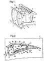
- One such nozzle guide vane ring is made up of a number of guide vane segments, one of which is illustrated in the perspective view of Figure 1, assembled in end-to-end abutment around the gas path.
- the guide vane segment generally indicated at 2 comprises radially inner and outer platform 4,6 respectively spaced apart to form the corresponding wall of the gas path.
- a plurality of hollow guide vanes such as that generally indicated at 8 extend in radial directions between the platforms 4,6.
- the interiors of the guide vanes 8 are supplied with cooling air shown by arrows 10 from a plenum cavity 11 immediately surrounding the outer platforms 6. It will be self evident, therefore, that in this particular example the cooling air flow 10 enters the interior 12 of the guide vanes 8 in a radially inward direction.
- FIG. 2 illustrates the interior of a guide vane in more detail.
- the hollow interior cavity 12 of the vane 8 is divided into several chambers by sheet metal inserts 14,16.
- the vane 8 is cast with a single internal cavity bounded by pressure and suction surface side walls 18,20 respectively and which converge towards the leading and trailing edges 22,24.
- the side walls 18,20 on their internal surfaces are provided with several integrally cast features, namely a plurality of discrete pedestals 26 (which appear in the drawings as inwardly facing "mushroom” shaped projections), spaced apart over the internal surface from approximately mid-chord towards the trailing edge 24, and a pair of opposite facing radial grooves 28,30 which extend full span height of the vane at approximately maximum chord.
- the first insert 14 extends the full span height of the blade and consists of a single roughly V-shaped sheet joined towards the trailing edge to form two side panels 14a,14b.
- the distal margins 32,34 of these panels are formed as flutes sized to engage the wall grooves 28,30 respectively.
- the insert 14 is sprung into the interior of the vane such that the flutes 32,34 engage wall grooves 28,30 and the tips of the plurality of pedestals 26 abut the surfaces of panels 14a,14b.
- the insert 14 thus constitutes a liner in the interior of the airfoil defining a cooling gap adjacent the interior surface of the side walls 18,20 the width of which is determined by the height of the pedestals 26.
- the second insert 16 comprises a separate panel or member which is slid into position across the gap between the flutes 32,34 of the first insert, and tends to reinforce engagement of the flutes with the wall grooves 28,30.
- This second insert may comprise a member or plate as described in our co-pending GB Patent Application No 9813251.7.
- Internal cooling consists of several elements: the interior volume 12 bounded by the insert panels 14a,14b and the insert 16 receives cooling air from a source (not shown) which enters through a radially outer end of the airfoil section ( Figure 1). A portion of this air passes through holes 17 in the panel 16 to form impingement cooling jets in a forward chamber or space 38 behind the airfoil leading edge 22. The remainder of the air entering the volume 12 is divided between impingement cooling holes 45 in the liner panels 14a,14b, the filtering or screening arrangement which supplies air into the liner wall cooling gap 42, and a small amount used to eject filtered oversize particulates.
- the walls 18,20 of the vane are pierced by a multiplicity of effusion cooling holes such as that indicated at 36 in Figures 1 and 2.
- the holes 36 communicate with a forward chamber 38 which is supplied with pressurised cooling air via the impingement holes 17 in the member 16.
- Corresponding effusion cooling holes 40 in the rearward part of the vane aft of partition 16 communicate with a narrow gap 42 created between insert 14 and the inner surface of the vane walls 18,20.
- the width of this gap 42 is determined by the height of the pedestals 26 against which the insert 14 is abutted.
- the pedestals 26 are isolated from each other and significantly increase the surface area of the vane walls 18,20 exposed to cooling flow and, of course, they co-operate to constituent multi-path, interconnected passages for the cooling flow.
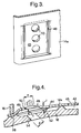
- Cooling air flow to the gap 42 is provided via a screening or gating arrangement shown in Figures 3 and 4 which removes particles above a predetermined size and discharges the screened particles into the gas path. At least a substantial proportion of the cooling flow through gap 42 (and in some arrangements all of it) enters the gap through a discriminating slot or screening barrier 44. Impingement cooling of the vanes walls 18 may also be provided through cooling holes 45 formed in the walls 14a,14b of the liner insert 14. The cooling air flowing through the space or gap 42 between liner 14 and vane walls 18,20 is exhausted either through the trailing edge 24 or the effusion cooling holes 40.
- a plenum 46 is formed by a concavity, in this particular embodiment a shallow rectangular sump 48, pressed into the wall of the insert panel 14a.
- the back wall of the sump 48 is pierced by a plurality of apertures 50 (three in the drawing, in general there is at least one such aperture) which provide open communication with the interior space 12 of the vane.
- the plenum 46, and therefore the sump 48 is located at the opposite end of the vane span to cooling air entry.
- the plenum 46 etc is located at the radially inner end of the vane span adjacent platform 4, and towards one of the grooves 28 which locates the partition member 16.
- two sides of the rectangular plenum 46 are not open to flow.
- One side adjacent the partition member 16 is closed by the member 16 forcing the panel 14a into sealing contact with the vane wall 18 along the edge of groove 28.
- a second side towards the inner platform 4 is effectively sealed by a floor 19 against which the radially inner edge of thhe panel 14a abuts.
- Air flow out of the plenum 46 into the gap 42 is possible on two sides so the screening gap 44 is formed on these sides between the surface of the insert panel 14a and a raised formation 52 in the vane wall 18.
- the raised formation 52 may constitute an "L-shaped" portion opposite two sides of the sump 48.
- the gap "f" in Figure 4 between the tip of the raised formation 52 and the panel 14a comprises a screening aperture which excludes particulates of greater size than gap width "f" from the cooling space 42.
- Oversize particles may therefore accumulate in the plenum 46 except there is provided discharge means leading from the plenum through the vane wall 18 into the external air flow comprising at least one discharge aperture 54.
- discharge means leading from the plenum through the vane wall 18 into the external air flow comprising at least one discharge aperture 54.
- the or each discharge aperture 54 is angled rearwardly and is positioned opposite a corresponding aperture 50 in the back wall of the plenum.
- the size(s) of the apertures 50,54 may be the same but this is not necessary. However the size of the apertures "e” and “d” respectively must be greater than the maximum size of particle permitted to pass through the remaining apertures. Furthermore the width "f" of the screening slot 44 must be less than the size "h” of the effusion cooling holes 40 leading from the wall gap 42 through the vane walls 18.
- cooling air enters the main cavity 12 of the vane; a proportion passes through partition 16 into the forward cavity for discharge through leading edge surface film cooling holes 36, a further proportion is utilised for impingement cooling of vane walls 18,20 through holes 45 in the insert panels 14a,14b; and the balance is inducted into the space 42 between the panels and the vane walls through plenum 46 and screening gap 44.
- the common path is these cooling flows is the first section in cavity 12 and experience reveals that larger particulates in the flow tend to accumulate at the downstream end of this section.
- the plenum 46 is located in this region and the path through discharge apertures 46,54 is effective in removing the larger particles by ejecting the particulates in a stream of air passing from inner aperture(s) 50 through the plenum chamber 46 and exiting into the gas path through outer aperture(s) 54.
Landscapes
- Engineering & Computer Science (AREA)
- Mechanical Engineering (AREA)
- General Engineering & Computer Science (AREA)
- Chemical & Material Sciences (AREA)
- Combustion & Propulsion (AREA)
- Turbine Rotor Nozzle Sealing (AREA)
Applications Claiming Priority (2)
| Application Number | Priority Date | Filing Date | Title |
|---|---|---|---|
| GB9913393 | 1999-06-09 | ||
| GB9913393A GB2350867B (en) | 1999-06-09 | 1999-06-09 | Gas turbine airfoil internal air system |
Publications (4)
| Publication Number | Publication Date |
|---|---|
| EP1059418A2 true EP1059418A2 (fr) | 2000-12-13 |
| EP1059418A3 EP1059418A3 (fr) | 2003-10-01 |
| EP1059418B1 EP1059418B1 (fr) | 2005-05-11 |
| EP1059418B8 EP1059418B8 (fr) | 2006-11-15 |
Family
ID=10855004
Family Applications (1)
| Application Number | Title | Priority Date | Filing Date |
|---|---|---|---|
| EP00304543A Expired - Lifetime EP1059418B8 (fr) | 1999-06-09 | 2000-05-26 | Système de refroidissement interne à air pour des aubes de turbine |
Country Status (4)
| Country | Link |
|---|---|
| US (1) | US6318963B1 (fr) |
| EP (1) | EP1059418B8 (fr) |
| DE (1) | DE60020007T2 (fr) |
| GB (1) | GB2350867B (fr) |
Cited By (7)
| Publication number | Priority date | Publication date | Assignee | Title |
|---|---|---|---|---|
| EP1275818A1 (fr) * | 2001-07-13 | 2003-01-15 | ALSTOM (Switzerland) Ltd | Matériau de base avec trou de refroidissement |
| WO2003080998A1 (fr) * | 2002-03-25 | 2003-10-02 | Alstom Technology Ltd | Aube de turbine refroidie |
| EP1510659A3 (fr) * | 2003-08-28 | 2008-05-14 | United Technologies Corporation | Séparateur de particules solides pour le circuit de refroidissement d'une aube de turbine |
| EP2233694A1 (fr) * | 2009-03-26 | 2010-09-29 | United Technologies Corporation | Mesure d'éléments d'espacement pour déflecteur de surface portante |
| EP2011970A3 (fr) * | 2007-07-06 | 2012-03-21 | United Technologies Corporation | Profils aérodynamiques renforcés |
| EP2573325A1 (fr) * | 2011-09-23 | 2013-03-27 | Siemens Aktiengesellschaft | Refroidissement par projection d'aubes ou pales de turbine |
| EP3266983A1 (fr) * | 2016-07-08 | 2018-01-10 | United Technologies Corporation | Système de refroidissement d'aube d'une turbine à gaz |
Families Citing this family (43)
| Publication number | Priority date | Publication date | Assignee | Title |
|---|---|---|---|---|
| GB2365932B (en) * | 2000-08-18 | 2004-05-05 | Rolls Royce Plc | Vane assembly |
| GB2366600A (en) * | 2000-09-09 | 2002-03-13 | Rolls Royce Plc | Cooling arrangement for trailing edge of aerofoil |
| US6652220B2 (en) | 2001-11-15 | 2003-11-25 | General Electric Company | Methods and apparatus for cooling gas turbine nozzles |
| GB2441771B (en) * | 2006-09-13 | 2009-07-08 | Rolls Royce Plc | Cooling arrangement for a component of a gas turbine engine |
| US7762784B2 (en) * | 2007-01-11 | 2010-07-27 | United Technologies Corporation | Insertable impingement rib |
| US10286407B2 (en) | 2007-11-29 | 2019-05-14 | General Electric Company | Inertial separator |
| JP2009162119A (ja) * | 2008-01-08 | 2009-07-23 | Ihi Corp | タービン翼の冷却構造 |
| US20100054915A1 (en) * | 2008-08-28 | 2010-03-04 | United Technologies Corporation | Airfoil insert |
| US8157525B2 (en) * | 2008-11-20 | 2012-04-17 | General Electric Company | Methods and apparatus relating to turbine airfoil cooling apertures |
| US8079821B2 (en) * | 2009-05-05 | 2011-12-20 | Siemens Energy, Inc. | Turbine airfoil with dual wall formed from inner and outer layers separated by a compliant structure |
| JP5675081B2 (ja) * | 2009-11-25 | 2015-02-25 | 三菱重工業株式会社 | 翼体及びこの翼体を備えたガスタービン |
| US8449249B2 (en) * | 2010-04-09 | 2013-05-28 | Williams International Co., L.L.C. | Turbine nozzle apparatus and associated method of manufacture |
| EP2392775A1 (fr) * | 2010-06-07 | 2011-12-07 | Siemens Aktiengesellschaft | Aude mobile à utiliser dans un écoulement de fluide d'une turbine et turbine correspondant |
| GB201103317D0 (fr) | 2011-02-28 | 2011-04-13 | Rolls Royce Plc | |
| US9127560B2 (en) | 2011-12-01 | 2015-09-08 | General Electric Company | Cooled turbine blade and method for cooling a turbine blade |
| US20140093392A1 (en) * | 2012-10-03 | 2014-04-03 | Rolls-Royce Plc | Gas turbine engine component |
| WO2014133721A1 (fr) * | 2013-02-27 | 2014-09-04 | United Technologies Corporation | Profil aérodynamique d'aube composite à paroi mince de turbine à gaz |
| EP2921649B1 (fr) * | 2014-03-19 | 2021-04-28 | Ansaldo Energia IP UK Limited | Partie de profil aérodynamique d'une pale de rotor ou aube directrice d'une turbomachine |
| FR3021698B1 (fr) * | 2014-05-28 | 2021-07-02 | Snecma | Aube de turbine, comprenant un conduit central de refroidissement isole thermiquement de parois de l'aube par deux cavites laterales jointives en aval du conduit central |
| US11033845B2 (en) | 2014-05-29 | 2021-06-15 | General Electric Company | Turbine engine and particle separators therefore |
| EP3149311A2 (fr) | 2014-05-29 | 2017-04-05 | General Electric Company | Moteur de turbine, et épurateurs de particules pour celui-ci |
| US10975731B2 (en) | 2014-05-29 | 2021-04-13 | General Electric Company | Turbine engine, components, and methods of cooling same |
| US9915176B2 (en) | 2014-05-29 | 2018-03-13 | General Electric Company | Shroud assembly for turbine engine |
| US9988913B2 (en) | 2014-07-15 | 2018-06-05 | United Technologies Corporation | Using inserts to balance heat transfer and stress in high temperature alloys |
| US10167725B2 (en) | 2014-10-31 | 2019-01-01 | General Electric Company | Engine component for a turbine engine |
| US10036319B2 (en) | 2014-10-31 | 2018-07-31 | General Electric Company | Separator assembly for a gas turbine engine |
| US10260353B2 (en) * | 2014-12-04 | 2019-04-16 | Rolls-Royce Corporation | Controlling exit side geometry of formed holes |
| FR3039199B1 (fr) * | 2015-07-20 | 2019-12-13 | Safran Helicopter Engines | Aubage de distributeur haute pression avec un insert a geometrie variable |
| US10428664B2 (en) | 2015-10-15 | 2019-10-01 | General Electric Company | Nozzle for a gas turbine engine |
| US9988936B2 (en) | 2015-10-15 | 2018-06-05 | General Electric Company | Shroud assembly for a gas turbine engine |
| US10174620B2 (en) | 2015-10-15 | 2019-01-08 | General Electric Company | Turbine blade |
| US10704425B2 (en) | 2016-07-14 | 2020-07-07 | General Electric Company | Assembly for a gas turbine engine |
| US10408062B2 (en) * | 2016-08-12 | 2019-09-10 | General Electric Company | Impingement system for an airfoil |
| US10364685B2 (en) * | 2016-08-12 | 2019-07-30 | Gneral Electric Company | Impingement system for an airfoil |
| US10443397B2 (en) * | 2016-08-12 | 2019-10-15 | General Electric Company | Impingement system for an airfoil |
| US10436048B2 (en) * | 2016-08-12 | 2019-10-08 | General Electric Comapny | Systems for removing heat from turbine components |
| GB2555632A (en) * | 2016-11-07 | 2018-05-09 | Rolls Royce Plc | Self-sealing impingement cooling tube for a turbine vane |
| US20190301286A1 (en) * | 2018-03-28 | 2019-10-03 | United Technologies Corporation | Airfoils for gas turbine engines |
| US10900362B2 (en) * | 2019-01-14 | 2021-01-26 | General Electric Company | Insert system for an airfoil and method of installing same |
| US11085374B2 (en) * | 2019-12-03 | 2021-08-10 | General Electric Company | Impingement insert with spring element for hot gas path component |
| US11525397B2 (en) * | 2020-09-01 | 2022-12-13 | General Electric Company | Gas turbine component with ejection circuit for removing debris from cooling air supply |
| CN114961875A (zh) * | 2022-05-29 | 2022-08-30 | 中国船舶重工集团公司第七0三研究所 | 一种压力侧排气的气冷涡轮动叶尾缘结构 |
| CN115075891A (zh) * | 2022-05-29 | 2022-09-20 | 中国船舶重工集团公司第七0三研究所 | 一种压力侧排气的气冷涡轮导叶尾缘结构 |
Family Cites Families (13)
| Publication number | Priority date | Publication date | Assignee | Title |
|---|---|---|---|---|
| US4063851A (en) * | 1975-12-22 | 1977-12-20 | United Technologies Corporation | Coolable turbine airfoil |
| US4257734A (en) * | 1978-03-22 | 1981-03-24 | Rolls-Royce Limited | Guide vanes for gas turbine engines |
| FR2473621A1 (fr) * | 1980-01-10 | 1981-07-17 | Snecma | Aube de distributeur de turbine |
| GB2067674B (en) * | 1980-01-23 | 1983-10-19 | Rolls Royce | Rotor blade for a gas turbine engine |
| US4820123A (en) * | 1988-04-25 | 1989-04-11 | United Technologies Corporation | Dirt removal means for air cooled blades |
| US4962640A (en) * | 1989-02-06 | 1990-10-16 | Westinghouse Electric Corp. | Apparatus and method for cooling a gas turbine vane |
| JPH0663442B2 (ja) * | 1989-09-04 | 1994-08-22 | 株式会社日立製作所 | タービン翼 |
| US5403159A (en) * | 1992-11-30 | 1995-04-04 | United Technoligies Corporation | Coolable airfoil structure |
| JPH07279612A (ja) * | 1994-04-14 | 1995-10-27 | Mitsubishi Heavy Ind Ltd | 重質油焚き用ガスタービン冷却翼 |
| DE19612840A1 (de) * | 1996-03-30 | 1997-10-02 | Abb Research Ltd | Vorrichtung und Verfahren zur Kühlung einer einseitig von Heissgas umgebenen Wand |
| US5827043A (en) * | 1997-06-27 | 1998-10-27 | United Technologies Corporation | Coolable airfoil |
| GB2343486B (en) * | 1998-06-19 | 2000-09-20 | Rolls Royce Plc | Improvemnts in or relating to cooling systems for gas turbine engine airfoil |
| US6238182B1 (en) * | 1999-02-19 | 2001-05-29 | Meyer Tool, Inc. | Joint for a turbine component |
-
1999
- 1999-06-09 GB GB9913393A patent/GB2350867B/en not_active Expired - Fee Related
-
2000
- 2000-05-26 DE DE60020007T patent/DE60020007T2/de not_active Expired - Lifetime
- 2000-05-26 EP EP00304543A patent/EP1059418B8/fr not_active Expired - Lifetime
- 2000-05-30 US US09/580,595 patent/US6318963B1/en not_active Expired - Lifetime
Cited By (15)
| Publication number | Priority date | Publication date | Assignee | Title |
|---|---|---|---|---|
| EP1548237A3 (fr) * | 2001-07-13 | 2005-08-03 | Alstom Technology Ltd | Composant d'une turbine à gaz avec un perçage de refroidissement |
| US7052233B2 (en) | 2001-07-13 | 2006-05-30 | Alstom Switzerland Ltd | Base material with cooling air hole |
| EP1275818A1 (fr) * | 2001-07-13 | 2003-01-15 | ALSTOM (Switzerland) Ltd | Matériau de base avec trou de refroidissement |
| WO2003080998A1 (fr) * | 2002-03-25 | 2003-10-02 | Alstom Technology Ltd | Aube de turbine refroidie |
| US7293962B2 (en) | 2002-03-25 | 2007-11-13 | Alstom Technology Ltd. | Cooled turbine blade or vane |
| EP1510659A3 (fr) * | 2003-08-28 | 2008-05-14 | United Technologies Corporation | Séparateur de particules solides pour le circuit de refroidissement d'une aube de turbine |
| EP2011970A3 (fr) * | 2007-07-06 | 2012-03-21 | United Technologies Corporation | Profils aérodynamiques renforcés |
| EP2233694A1 (fr) * | 2009-03-26 | 2010-09-29 | United Technologies Corporation | Mesure d'éléments d'espacement pour déflecteur de surface portante |
| US8109724B2 (en) | 2009-03-26 | 2012-02-07 | United Technologies Corporation | Recessed metering standoffs for airfoil baffle |
| US8480366B2 (en) | 2009-03-26 | 2013-07-09 | United Technologies Corporation | Recessed metering standoffs for airfoil baffle |
| EP2573325A1 (fr) * | 2011-09-23 | 2013-03-27 | Siemens Aktiengesellschaft | Refroidissement par projection d'aubes ou pales de turbine |
| WO2013041361A1 (fr) | 2011-09-23 | 2013-03-28 | Siemens Aktiengesellschaft | Refroidissement par contact d'aubes ou de pales de turbine |
| US9777581B2 (en) | 2011-09-23 | 2017-10-03 | Siemens Aktiengesellschaft | Impingement cooling of turbine blades or vanes |
| EP3266983A1 (fr) * | 2016-07-08 | 2018-01-10 | United Technologies Corporation | Système de refroidissement d'aube d'une turbine à gaz |
| US10344619B2 (en) | 2016-07-08 | 2019-07-09 | United Technologies Corporation | Cooling system for a gaspath component of a gas powered turbine |
Also Published As
| Publication number | Publication date |
|---|---|
| EP1059418B8 (fr) | 2006-11-15 |
| DE60020007T2 (de) | 2006-03-16 |
| DE60020007D1 (de) | 2005-06-16 |
| GB2350867B (en) | 2003-03-19 |
| US6318963B1 (en) | 2001-11-20 |
| GB9913393D0 (en) | 1999-08-11 |
| EP1059418B1 (fr) | 2005-05-11 |
| EP1059418A3 (fr) | 2003-10-01 |
| GB2350867A (en) | 2000-12-13 |
Similar Documents
| Publication | Publication Date | Title |
|---|---|---|
| EP1059418B1 (fr) | Système de refroidissement interne à air pour des aubes de turbine | |
| US6238183B1 (en) | Cooling systems for gas turbine engine airfoil | |
| JP6312929B2 (ja) | プラットフォームにおいて、前方、弦中央および後方の冷却チャンバを有する冷却されるタービンベーンプラットフォーム | |
| US7497655B1 (en) | Turbine airfoil with near-wall impingement and vortex cooling | |
| EP1106781B1 (fr) | Aube refroidie de rotor ou de stator de turbomachine | |
| US6017189A (en) | Cooling system for turbine blade platforms | |
| JP3997986B2 (ja) | 冷却タービン部品、及び冷却タービン翼 | |
| US3781129A (en) | Cooled airfoil | |
| JPH0366481B2 (fr) | ||
| US4474532A (en) | Coolable airfoil for a rotary machine | |
| JP4508482B2 (ja) | ガスタービン静翼 | |
| KR100573658B1 (ko) | 터빈 요소 | |
| US6398486B1 (en) | Steam exit flow design for aft cavities of an airfoil | |
| CA2560811C (fr) | Evacuation d'extremite de bord de fuite de profil refroidi | |
| EP1443178A2 (fr) | Aube de turbine | |
| EP1219784B1 (fr) | Dispositif et procédé de refroidissement local des parois des anneaux de guidage des turbines à gaz | |
| EP2812539A1 (fr) | Ensemble turbine, tube de refroidissement par impact et moteur à turbine à gaz correspondants | |
| EP0924383A2 (fr) | Aube de turbine avec refrodissement de la racine de l'arête aval | |
| CN108979737B (zh) | 具有插入件的发动机部件及其内分离灰尘的方法 | |
| EP1156187A2 (fr) | Insert de refroidissement par impact d'une aube de guidage | |
| JPH08503533A (ja) | 内部冷却タービン | |
| JPH0223202A (ja) | 内部冷却タービンブレード及び内部冷却タービンブレード用塵埃除去装置 | |
| JPH10159501A (ja) | エアフォイル | |
| US6474947B1 (en) | Film cooling hole construction in gas turbine moving-vanes | |
| GB2413160A (en) | A rotor blade tip cooling arrangement |
Legal Events
| Date | Code | Title | Description |
|---|---|---|---|
| PUAI | Public reference made under article 153(3) epc to a published international application that has entered the european phase |
Free format text: ORIGINAL CODE: 0009012 |
|
| AK | Designated contracting states |
Kind code of ref document: A2 Designated state(s): AT BE CH CY DE DK ES FI FR GB GR IE IT LI LU MC NL PT SE |
|
| AX | Request for extension of the european patent |
Free format text: AL;LT;LV;MK;RO;SI |
|
| PUAL | Search report despatched |
Free format text: ORIGINAL CODE: 0009013 |
|
| AK | Designated contracting states |
Kind code of ref document: A3 Designated state(s): AT BE CH CY DE DK ES FI FR GB GR IE IT LI LU MC NL PT SE |
|
| AX | Request for extension of the european patent |
Extension state: AL LT LV MK RO SI |
|
| RIC1 | Information provided on ipc code assigned before grant |
Ipc: 7F 01D 25/32 B Ipc: 7F 01D 5/18 A |
|
| 17P | Request for examination filed |
Effective date: 20031018 |
|
| 17Q | First examination report despatched |
Effective date: 20040329 |
|
| AKX | Designation fees paid |
Designated state(s): DE FR GB |
|
| GRAP | Despatch of communication of intention to grant a patent |
Free format text: ORIGINAL CODE: EPIDOSNIGR1 |
|
| GRAS | Grant fee paid |
Free format text: ORIGINAL CODE: EPIDOSNIGR3 |
|
| GRAA | (expected) grant |
Free format text: ORIGINAL CODE: 0009210 |
|
| AK | Designated contracting states |
Kind code of ref document: B1 Designated state(s): DE FR GB |
|
| REG | Reference to a national code |
Ref country code: GB Ref legal event code: FG4D |
|
| PGFP | Annual fee paid to national office [announced via postgrant information from national office to epo] |
Ref country code: GB Payment date: 20050516 Year of fee payment: 6 |
|
| REG | Reference to a national code |
Ref country code: IE Ref legal event code: FG4D |
|
| REF | Corresponds to: |
Ref document number: 60020007 Country of ref document: DE Date of ref document: 20050616 Kind code of ref document: P |
|
| ET | Fr: translation filed | ||
| PLBE | No opposition filed within time limit |
Free format text: ORIGINAL CODE: 0009261 |
|
| STAA | Information on the status of an ep patent application or granted ep patent |
Free format text: STATUS: NO OPPOSITION FILED WITHIN TIME LIMIT |
|
| 26N | No opposition filed |
Effective date: 20060214 |
|
| RBV | Designated contracting states (corrected) |
Designated state(s): DE FR |
|
| REG | Reference to a national code |
Ref country code: FR Ref legal event code: PLFP Year of fee payment: 17 |
|
| REG | Reference to a national code |
Ref country code: FR Ref legal event code: PLFP Year of fee payment: 18 |
|
| REG | Reference to a national code |
Ref country code: FR Ref legal event code: CA Effective date: 20170517 |
|
| PGFP | Annual fee paid to national office [announced via postgrant information from national office to epo] |
Ref country code: DE Payment date: 20170530 Year of fee payment: 18 Ref country code: FR Payment date: 20170525 Year of fee payment: 18 |
|
| REG | Reference to a national code |
Ref country code: DE Ref legal event code: R119 Ref document number: 60020007 Country of ref document: DE |
|
| PG25 | Lapsed in a contracting state [announced via postgrant information from national office to epo] |
Ref country code: FR Free format text: LAPSE BECAUSE OF NON-PAYMENT OF DUE FEES Effective date: 20180531 Ref country code: DE Free format text: LAPSE BECAUSE OF NON-PAYMENT OF DUE FEES Effective date: 20181201 |