EP1059458A2 - Dispositif de commande fluidique - Google Patents
Dispositif de commande fluidique Download PDFInfo
- Publication number
- EP1059458A2 EP1059458A2 EP00104940A EP00104940A EP1059458A2 EP 1059458 A2 EP1059458 A2 EP 1059458A2 EP 00104940 A EP00104940 A EP 00104940A EP 00104940 A EP00104940 A EP 00104940A EP 1059458 A2 EP1059458 A2 EP 1059458A2
- Authority
- EP
- European Patent Office
- Prior art keywords
- devices
- individual devices
- control device
- fluid
- individual
- Prior art date
- Legal status (The legal status is an assumption and is not a legal conclusion. Google has not performed a legal analysis and makes no representation as to the accuracy of the status listed.)
- Granted
Links
- 239000012530 fluid Substances 0.000 title claims abstract description 44
- 238000009434 installation Methods 0.000 description 5
- 238000005516 engineering process Methods 0.000 description 3
- 238000010276 construction Methods 0.000 description 2
- 230000004308 accommodation Effects 0.000 description 1
- 210000000988 bone and bone Anatomy 0.000 description 1
- 238000004891 communication Methods 0.000 description 1
- 230000001276 controlling effect Effects 0.000 description 1
- 230000001419 dependent effect Effects 0.000 description 1
- 238000011161 development Methods 0.000 description 1
- 230000018109 developmental process Effects 0.000 description 1
- 230000010354 integration Effects 0.000 description 1
- 238000004519 manufacturing process Methods 0.000 description 1
- 230000003287 optical effect Effects 0.000 description 1
- 238000004806 packaging method and process Methods 0.000 description 1
- 230000001105 regulatory effect Effects 0.000 description 1
- 238000007789 sealing Methods 0.000 description 1
- 230000003584 silencer Effects 0.000 description 1
- 238000009423 ventilation Methods 0.000 description 1
Images
Classifications
-
- F—MECHANICAL ENGINEERING; LIGHTING; HEATING; WEAPONS; BLASTING
- F15—FLUID-PRESSURE ACTUATORS; HYDRAULICS OR PNEUMATICS IN GENERAL
- F15B—SYSTEMS ACTING BY MEANS OF FLUIDS IN GENERAL; FLUID-PRESSURE ACTUATORS, e.g. SERVOMOTORS; DETAILS OF FLUID-PRESSURE SYSTEMS, NOT OTHERWISE PROVIDED FOR
- F15B13/00—Details of servomotor systems ; Valves for servomotor systems
- F15B13/02—Fluid distribution or supply devices characterised by their adaptation to the control of servomotors
- F15B13/06—Fluid distribution or supply devices characterised by their adaptation to the control of servomotors for use with two or more servomotors
- F15B13/08—Assemblies of units, each for the control of a single servomotor only
- F15B13/0803—Modular units
- F15B13/0832—Modular valves
- F15B13/0839—Stacked plate type valves
-
- F—MECHANICAL ENGINEERING; LIGHTING; HEATING; WEAPONS; BLASTING
- F15—FLUID-PRESSURE ACTUATORS; HYDRAULICS OR PNEUMATICS IN GENERAL
- F15B—SYSTEMS ACTING BY MEANS OF FLUIDS IN GENERAL; FLUID-PRESSURE ACTUATORS, e.g. SERVOMOTORS; DETAILS OF FLUID-PRESSURE SYSTEMS, NOT OTHERWISE PROVIDED FOR
- F15B13/00—Details of servomotor systems ; Valves for servomotor systems
- F15B13/02—Fluid distribution or supply devices characterised by their adaptation to the control of servomotors
- F15B13/06—Fluid distribution or supply devices characterised by their adaptation to the control of servomotors for use with two or more servomotors
- F15B13/08—Assemblies of units, each for the control of a single servomotor only
- F15B13/0803—Modular units
- F15B13/0807—Manifolds
- F15B13/0814—Monoblock manifolds
-
- F—MECHANICAL ENGINEERING; LIGHTING; HEATING; WEAPONS; BLASTING
- F15—FLUID-PRESSURE ACTUATORS; HYDRAULICS OR PNEUMATICS IN GENERAL
- F15B—SYSTEMS ACTING BY MEANS OF FLUIDS IN GENERAL; FLUID-PRESSURE ACTUATORS, e.g. SERVOMOTORS; DETAILS OF FLUID-PRESSURE SYSTEMS, NOT OTHERWISE PROVIDED FOR
- F15B13/00—Details of servomotor systems ; Valves for servomotor systems
- F15B13/02—Fluid distribution or supply devices characterised by their adaptation to the control of servomotors
- F15B13/06—Fluid distribution or supply devices characterised by their adaptation to the control of servomotors for use with two or more servomotors
- F15B13/08—Assemblies of units, each for the control of a single servomotor only
- F15B13/0803—Modular units
- F15B13/0821—Attachment or sealing of modular units to each other
- F15B13/0825—Attachment or sealing of modular units to each other the modular elements being mounted on a common member, e.g. on a rail
-
- F—MECHANICAL ENGINEERING; LIGHTING; HEATING; WEAPONS; BLASTING
- F15—FLUID-PRESSURE ACTUATORS; HYDRAULICS OR PNEUMATICS IN GENERAL
- F15B—SYSTEMS ACTING BY MEANS OF FLUIDS IN GENERAL; FLUID-PRESSURE ACTUATORS, e.g. SERVOMOTORS; DETAILS OF FLUID-PRESSURE SYSTEMS, NOT OTHERWISE PROVIDED FOR
- F15B13/00—Details of servomotor systems ; Valves for servomotor systems
- F15B13/02—Fluid distribution or supply devices characterised by their adaptation to the control of servomotors
- F15B13/06—Fluid distribution or supply devices characterised by their adaptation to the control of servomotors for use with two or more servomotors
- F15B13/08—Assemblies of units, each for the control of a single servomotor only
- F15B13/0803—Modular units
- F15B13/0846—Electrical details
- F15B13/0853—Electric circuit boards
-
- F—MECHANICAL ENGINEERING; LIGHTING; HEATING; WEAPONS; BLASTING
- F15—FLUID-PRESSURE ACTUATORS; HYDRAULICS OR PNEUMATICS IN GENERAL
- F15B—SYSTEMS ACTING BY MEANS OF FLUIDS IN GENERAL; FLUID-PRESSURE ACTUATORS, e.g. SERVOMOTORS; DETAILS OF FLUID-PRESSURE SYSTEMS, NOT OTHERWISE PROVIDED FOR
- F15B13/00—Details of servomotor systems ; Valves for servomotor systems
- F15B13/02—Fluid distribution or supply devices characterised by their adaptation to the control of servomotors
- F15B13/06—Fluid distribution or supply devices characterised by their adaptation to the control of servomotors for use with two or more servomotors
- F15B13/08—Assemblies of units, each for the control of a single servomotor only
- F15B13/0803—Modular units
- F15B13/0846—Electrical details
- F15B13/0857—Electrical connecting means, e.g. plugs, sockets
-
- F—MECHANICAL ENGINEERING; LIGHTING; HEATING; WEAPONS; BLASTING
- F15—FLUID-PRESSURE ACTUATORS; HYDRAULICS OR PNEUMATICS IN GENERAL
- F15B—SYSTEMS ACTING BY MEANS OF FLUIDS IN GENERAL; FLUID-PRESSURE ACTUATORS, e.g. SERVOMOTORS; DETAILS OF FLUID-PRESSURE SYSTEMS, NOT OTHERWISE PROVIDED FOR
- F15B13/00—Details of servomotor systems ; Valves for servomotor systems
- F15B13/02—Fluid distribution or supply devices characterised by their adaptation to the control of servomotors
- F15B13/06—Fluid distribution or supply devices characterised by their adaptation to the control of servomotors for use with two or more servomotors
- F15B13/08—Assemblies of units, each for the control of a single servomotor only
- F15B13/0803—Modular units
- F15B13/0846—Electrical details
- F15B13/086—Sensing means, e.g. pressure sensors
-
- F—MECHANICAL ENGINEERING; LIGHTING; HEATING; WEAPONS; BLASTING
- F15—FLUID-PRESSURE ACTUATORS; HYDRAULICS OR PNEUMATICS IN GENERAL
- F15B—SYSTEMS ACTING BY MEANS OF FLUIDS IN GENERAL; FLUID-PRESSURE ACTUATORS, e.g. SERVOMOTORS; DETAILS OF FLUID-PRESSURE SYSTEMS, NOT OTHERWISE PROVIDED FOR
- F15B13/00—Details of servomotor systems ; Valves for servomotor systems
- F15B13/02—Fluid distribution or supply devices characterised by their adaptation to the control of servomotors
- F15B13/06—Fluid distribution or supply devices characterised by their adaptation to the control of servomotors for use with two or more servomotors
- F15B13/08—Assemblies of units, each for the control of a single servomotor only
- F15B13/0803—Modular units
- F15B13/0846—Electrical details
- F15B13/0867—Data bus systems
-
- F—MECHANICAL ENGINEERING; LIGHTING; HEATING; WEAPONS; BLASTING
- F15—FLUID-PRESSURE ACTUATORS; HYDRAULICS OR PNEUMATICS IN GENERAL
- F15B—SYSTEMS ACTING BY MEANS OF FLUIDS IN GENERAL; FLUID-PRESSURE ACTUATORS, e.g. SERVOMOTORS; DETAILS OF FLUID-PRESSURE SYSTEMS, NOT OTHERWISE PROVIDED FOR
- F15B13/00—Details of servomotor systems ; Valves for servomotor systems
- F15B13/02—Fluid distribution or supply devices characterised by their adaptation to the control of servomotors
- F15B13/06—Fluid distribution or supply devices characterised by their adaptation to the control of servomotors for use with two or more servomotors
- F15B13/08—Assemblies of units, each for the control of a single servomotor only
- F15B13/0803—Modular units
- F15B13/0878—Assembly of modular units
- F15B13/0885—Assembly of modular units using valves combined with other components
- F15B13/0889—Valves combined with electrical components
Definitions
- the invention relates to a fluid power control device, the several successively arranged in a row direction and individual devices combined to form a battery-like unit contains.
- a fluid power control device of this type is possible, for example from DE 44 13 657 C1.
- Control device In the case of a fluid technology that is derived from US Pat. No. 4,861,232 Control device are also several individual devices to one battery-like unit summarized.
- the individual devices here are vacuum generating devices, through which vacuum can be created if required can generate that can be used in handling devices is to vacuum objects too transport and handle.
- a fluid power control unit with several in a row in a row arranged and combined into a battery-like unit
- Individual devices of different types at least are partially designed as fluid devices and their Device housing, if it matches the row direction Seen from a direction, at least essentially have identical outer contours.
- the fluid devices among the individual devices can for example at least partially as valve devices and / or as vacuum generator devices and / or as pure electronic or electrical devices be executed.
- Valve units and vacuum generator units in one control unit summarize.
- you can also electronic devices are integrated, for example electronic Regulator, which is a regulated electronic control allow electrical components of a machine or system.
- electronic Regulator which is a regulated electronic control allow electrical components of a machine or system.
- the possible combinations are very diverse, being due to the matching outer contouring usually also the order of placement within the battery-like Unit can be varied as needed and in particular there is the possibility of a fluid power control unit individually with those for a special control purpose equip the required individual device types.
- the individual devices can be connected to a mechanical connection self-supporting assembly can be summarized, like this for example from DE 44 13 657 C1. Possible would also be an assembly of the individual devices on a common Equipment carrier, as explained in US 4,861,232 becomes. In the latter case, there is also a modular design of the device carrier conceivable, for example, that each individual device on a specially adapted device carrier module sits, with the device carrier modules in turn are mechanically connected to each other to finally the equipment carrier to obtain.
- the device housing of the individual devices can have a plate-like shape have, with their larger side surfaces expediently are oriented in and against the row direction.
- width dimensions measured in the row direction the device housing in particular depending on the respective Device type may vary, a structure appears with identical width dimensions of the individual device types in particular advantageous because it is a particularly simple one Standardization of interfaces to external institutions, Realize cables, fluid lines or the like leaves.
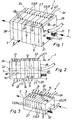
- the drawing shows different embodiments of a Fluid power control unit 1, which is used to control a Machine, a system or individual tools can be used is, the devices to be controlled at least fluid, for example pneumatically and / or hydraulically, operate.
- the control devices preferably enable also the control of electrical equipment, for example the control of electrically operated Valves or electrically operated drives.
- control devices 1 have in common that they are a Contain a plurality of individual devices 2, which in one by an arrow indicated row direction 3 in succession arranged and to a battery-like device unit 4 are summarized.
- the device housing 5 of the various individual devices 2 are standardized in terms of their external shape. At Consideration in the direction of row direction 3 results for the device housing 5 of all individual devices 2 at least one essentially and preferably overall identical outer contour. According to the illustrations, this can be a act rectangular outer contour of the individual devices 2.
- two as pure electronic and / or electrical devices 7 executed individual devices 2 available, according to Figure 3 is only such an electronic and / or electrical device 7 is available.
- the fluid devices 6 within a respective control device 1 can also be of different types. So are according to Figures 1 and 2 two fluid devices 6 as valve devices 8 and two further fluid devices 6 designed as vacuum generator devices 9. The embodiment according to FIG. 3 contains four valve devices 8 and four vacuum generating devices 9.
- valve devices 8 each contain at least one in FIG 2 only schematically indicated valve member 12, which in different Positions can be positioned, whereby for positioning electric drives are available, those over electric Contact means 13 the required actuation energy can be supplied. It can be piloted or act directly operated valve devices 8. Dependent on from the switching state of the respective valve device 8 Control of fluidically connected consumers, for example fluid-operated drives, with corresponding fluid lines are indicated at 14 in FIG.
- the valve devices 8 can be pneumatic and / or act hydraulic valve devices.
- the vacuum generator devices 9 are designed in outgoing Fluid lines 15 to generate a vacuum if necessary.
- This negative pressure can be used, for example, To do handling work, for example a transport and / or positioning of objects in the packaging industry or of workpieces in manufacturing and Assembly technology.
- the fluid lines 15 can be used for this purpose are connected with suitable suction cups or suction plates, that can be placed on the product to be handled.
- Vacuum generator units 16 are shown in dash-dot lines in FIG indicated, which are integrated in the vacuum generator devices 9 and which are usually ejector devices acts that work according to the jet pump principle.
- the one you want Operating status can be at least one in the relevant vacuum generator device 9 integrated control valve 17 influence, which is indicated by dash-dotted lines in Figure 2 is and its operating energy comparable to the valve devices 8 can be supplied via electrical contact means 13 '.
- Electronics or electrical devices 7 are, for example, as electronic controllers running through electrical outputs and / or inputs 18, which in connection with continuing electrical lines 22 electrical signals can be output and fed.
- this regulator For example, use an electronically controlled one Positioning of fluidic and / or electrical drives to make.
- the electronic and / or electrical devices 7 also have via electrical contact means 13 '' for feeding electrical Control signals.
- control electronics 23 is one of the Assigned to the long sides of the device unit 4, on this On the long side also the electrical contact means 13, 13 ', 13' ' are present, so that an electrical contact from one single side can be done.
- the control electronics 23 can include at least one printed circuit board that is extends across the various individual devices 2.
- control electronics 23 is provided in a control block 29, from which the individual devices 2 supplied with electrical actuation signals become.
- the Control electronics 23 contain their own control program and / or form a fieldbus unit, via the operator a connected fieldbus 24 communication with other control units or with a higher-level external one Control unit can be done.
- the individual devices 2 equipped with plate-like device housings 5, the two larger side surfaces in and against the Row direction 3 are oriented, the device housing 5th directly adjacent individual devices 2 directly to one another issue.
- device unit 4 detects one connected self-supporting assembly.
- the device unit 4 in the row direction 3 of one or more central channels is enforced, according to Figures 1 and 2 in total three such central channels 25 are present, of which in Figure 2 is indicated.
- Set these central channels 25 are composed of individual fluid channels 26, which the individual Push through device housing 5 in row direction 3 and align with each other to form the central channels 25.
- Intermediate Sealing measures result in a fluid tightness Connection between the various individual devices 2.
- a central channel 25 designed as a central feed channel through which a Pressure medium, in particular compressed air, into the device unit 4 is fed and from which the fluid devices 6 are fed.
- a Pressure medium in particular compressed air
- one or more central channels are available, which act as ventilation or relief channels and through which the used pressure medium is discharged again becomes.
- the vent can directly to the environment of the control unit 1 take place, preferably via suitable Silencer 27, which can be attached to control unit 1.
- the feeding and / or discharge of the pressure medium into or The device unit 4 expediently takes place on one End face with the intermediation of a separate, preferably plate-like end part 28, which on one of the two ends Individual devices 2 of the device unit 4 is attached.
- the distribution of the pressure medium takes place inside the fluid devices 6 to the internal facilities via unspecified internal fluid channels.
- the pure electronics or electrical devices 7 from one or several of the central channels 25 are interspersed corresponding fluid channels designed as pure through channels.
- Individual devices 2 are installed independently of one another on a plate or strip-shaped device carrier 32. Nevertheless, they are possible to obtain a compact arrangement arranged close to each other and can even touch.
- the equipment carrier can 32 as a one-piece component would be possible but also a modular structure with a subdivision into Row direction 3 consecutively arranged device carrier modules, which are fixed to each other by suitable connecting means be, so that there is a structure comparable to the device unit 4 can result according to Figures 1 and 2.
- the device housing has all individual devices 2 over the same width (measured in the row direction 3). It can also individual devices 2 of different widths combined become.
- a fluid power control unit 1 is particularly advantageous, that according to Figures 1 and 2 a cuboid and, with a corresponding Number of individual devices 2, also cube-like Has structure, being externally independent of the individual Equipped with individual devices 2 a uniform appearance results. Because the one required for the installation of the control unit Installation space regardless of the type of used Individual devices 2 with respect to the perpendicular to the row direction 3 required cross dimensions always remains the same the integration of the control units in the construction of a Plan the machine or system relatively easily.
Landscapes
- Engineering & Computer Science (AREA)
- Physics & Mathematics (AREA)
- Fluid Mechanics (AREA)
- Mechanical Engineering (AREA)
- General Engineering & Computer Science (AREA)
- Fluid-Pressure Circuits (AREA)
- Other Liquid Machine Or Engine Such As Wave Power Use (AREA)
Applications Claiming Priority (2)
| Application Number | Priority Date | Filing Date | Title |
|---|---|---|---|
| DE29909529U DE29909529U1 (de) | 1999-06-01 | 1999-06-01 | Fluidtechnisches Steuergerät |
| DE29909529U | 1999-06-01 |
Publications (3)
| Publication Number | Publication Date |
|---|---|
| EP1059458A2 true EP1059458A2 (fr) | 2000-12-13 |
| EP1059458A3 EP1059458A3 (fr) | 2003-10-15 |
| EP1059458B1 EP1059458B1 (fr) | 2006-05-10 |
Family
ID=8074202
Family Applications (1)
| Application Number | Title | Priority Date | Filing Date |
|---|---|---|---|
| EP20000104940 Revoked EP1059458B1 (fr) | 1999-06-01 | 2000-03-08 | Dispositif de commande fluidique |
Country Status (3)
| Country | Link |
|---|---|
| EP (1) | EP1059458B1 (fr) |
| DE (2) | DE29909529U1 (fr) |
| ES (1) | ES2259583T3 (fr) |
Cited By (28)
| Publication number | Priority date | Publication date | Assignee | Title |
|---|---|---|---|---|
| EP1308633A1 (fr) * | 2001-11-01 | 2003-05-07 | Korea Pneumatic System Co., Ltd | Dispositif pour l'obtention d'un vide |
| EP1316732A1 (fr) * | 2001-11-29 | 2003-06-04 | Festo AG & Co | Dispositif de travail actionné par un fluide |
| WO2002065221A3 (fr) * | 2001-02-13 | 2003-09-12 | Siemens Ag | Systeme pour le traitement automatise de fluides pourvu de modules de processus interchangeables et juxtaposables |
| GB2475835A (en) * | 2009-11-27 | 2011-06-08 | Magna Parva Ltd | Sample Processing System |
| EP2738396A1 (fr) * | 2012-12-01 | 2014-06-04 | FESTO AG & Co. KG | Agencement de vannes |
| CN104061361A (zh) * | 2013-03-20 | 2014-09-24 | 费斯托股份有限两合公司 | 阀装置 |
| WO2017204868A1 (fr) * | 2016-05-23 | 2017-11-30 | Becton, Dickinson And Company | Distributeur de liquide à support de collecteur pour canaux de pipette modulaires actionnés indépendamment |
| US10065185B2 (en) | 2007-07-13 | 2018-09-04 | Handylab, Inc. | Microfluidic cartridge |
| US10071376B2 (en) | 2007-07-13 | 2018-09-11 | Handylab, Inc. | Integrated apparatus for performing nucleic acid extraction and diagnostic testing on multiple biological samples |
| US10076754B2 (en) | 2011-09-30 | 2018-09-18 | Becton, Dickinson And Company | Unitized reagent strip |
| US10100302B2 (en) | 2007-07-13 | 2018-10-16 | Handylab, Inc. | Polynucleotide capture materials, and methods of using same |
| USD831843S1 (en) | 2011-09-30 | 2018-10-23 | Becton, Dickinson And Company | Single piece reagent holder |
| US10139012B2 (en) | 2007-07-13 | 2018-11-27 | Handylab, Inc. | Integrated heater and magnetic separator |
| US10179910B2 (en) | 2007-07-13 | 2019-01-15 | Handylab, Inc. | Rack for sample tubes and reagent holders |
| US10234474B2 (en) | 2007-07-13 | 2019-03-19 | Handylab, Inc. | Automated pipetting apparatus having a combined liquid pump and pipette head system |
| US10351901B2 (en) | 2001-03-28 | 2019-07-16 | Handylab, Inc. | Systems and methods for thermal actuation of microfluidic devices |
| US10364456B2 (en) | 2004-05-03 | 2019-07-30 | Handylab, Inc. | Method for processing polynucleotide-containing samples |
| US10571935B2 (en) | 2001-03-28 | 2020-02-25 | Handylab, Inc. | Methods and systems for control of general purpose microfluidic devices |
| US10695764B2 (en) | 2006-03-24 | 2020-06-30 | Handylab, Inc. | Fluorescence detector for microfluidic diagnostic system |
| US10710069B2 (en) | 2006-11-14 | 2020-07-14 | Handylab, Inc. | Microfluidic valve and method of making same |
| US10731201B2 (en) | 2003-07-31 | 2020-08-04 | Handylab, Inc. | Processing particle-containing samples |
| US10781482B2 (en) | 2011-04-15 | 2020-09-22 | Becton, Dickinson And Company | Scanning real-time microfluidic thermocycler and methods for synchronized thermocycling and scanning optical detection |
| US10799862B2 (en) | 2006-03-24 | 2020-10-13 | Handylab, Inc. | Integrated system for processing microfluidic samples, and method of using same |
| US10822644B2 (en) | 2012-02-03 | 2020-11-03 | Becton, Dickinson And Company | External files for distribution of molecular diagnostic tests and determination of compatibility between tests |
| US10900066B2 (en) | 2006-03-24 | 2021-01-26 | Handylab, Inc. | Microfluidic system for amplifying and detecting polynucleotides in parallel |
| US11142785B2 (en) | 2006-03-24 | 2021-10-12 | Handylab, Inc. | Microfluidic system for amplifying and detecting polynucleotides in parallel |
| US11453906B2 (en) | 2011-11-04 | 2022-09-27 | Handylab, Inc. | Multiplexed diagnostic detection apparatus and methods |
| US11806718B2 (en) | 2006-03-24 | 2023-11-07 | Handylab, Inc. | Fluorescence detector for microfluidic diagnostic system |
Families Citing this family (4)
| Publication number | Priority date | Publication date | Assignee | Title |
|---|---|---|---|---|
| DE20107330U1 (de) | 2001-04-20 | 2001-07-19 | FESTO AG & Co., 73734 Esslingen | Fluidtechnisches Steuergerät |
| EP1283369B1 (fr) | 2001-08-08 | 2006-12-13 | Festo AG & Co | Assemblage de valves de forme plate |
| DE20219497U1 (de) | 2002-12-17 | 2003-03-06 | FESTO AG & Co., 73734 Esslingen | Fluidtechnisches Steuergerät |
| WO2014210028A1 (fr) * | 2013-06-24 | 2014-12-31 | Spx Corporation | Dispositif hydraulique à pression équilibrée et procédé |
Citations (2)
| Publication number | Priority date | Publication date | Assignee | Title |
|---|---|---|---|---|
| US4861232A (en) | 1987-05-30 | 1989-08-29 | Myotoku Ltd. | Vacuum generating device |
| DE4413657C1 (de) | 1994-04-20 | 1995-11-02 | Festo Kg | Ventilanordnung |
Family Cites Families (4)
| Publication number | Priority date | Publication date | Assignee | Title |
|---|---|---|---|---|
| DE4111890C2 (de) * | 1991-04-09 | 1995-04-20 | Mannesmann Ag | Ventilbatterie, insbesondere für gasförmige Medien |
| DE4312757A1 (de) | 1993-04-20 | 1994-10-27 | Festo Kg | Elektronische Steuereinrichtung für eine modulartig aufgebaute Ventilstation |
| EP0704647B1 (fr) * | 1994-04-18 | 2001-08-16 | SMC Kabushiki Kaisha | Dispositif de raccordement de conduit de sortie et vanne |
| DE19711227C2 (de) | 1997-03-18 | 2000-11-30 | Festo Ag & Co | Ventilanordnung |
-
1999
- 1999-06-01 DE DE29909529U patent/DE29909529U1/de not_active Expired - Lifetime
-
2000
- 2000-03-08 ES ES00104940T patent/ES2259583T3/es not_active Expired - Lifetime
- 2000-03-08 DE DE50012712T patent/DE50012712D1/de not_active Expired - Lifetime
- 2000-03-08 EP EP20000104940 patent/EP1059458B1/fr not_active Revoked
Patent Citations (2)
| Publication number | Priority date | Publication date | Assignee | Title |
|---|---|---|---|---|
| US4861232A (en) | 1987-05-30 | 1989-08-29 | Myotoku Ltd. | Vacuum generating device |
| DE4413657C1 (de) | 1994-04-20 | 1995-11-02 | Festo Kg | Ventilanordnung |
Cited By (85)
| Publication number | Priority date | Publication date | Assignee | Title |
|---|---|---|---|---|
| WO2002065221A3 (fr) * | 2001-02-13 | 2003-09-12 | Siemens Ag | Systeme pour le traitement automatise de fluides pourvu de modules de processus interchangeables et juxtaposables |
| US6942785B2 (en) | 2001-02-13 | 2005-09-13 | Siemens Aktiengesellschaft | System for automated treatment of fluids having successive and interchangeable process modules |
| US10571935B2 (en) | 2001-03-28 | 2020-02-25 | Handylab, Inc. | Methods and systems for control of general purpose microfluidic devices |
| US10351901B2 (en) | 2001-03-28 | 2019-07-16 | Handylab, Inc. | Systems and methods for thermal actuation of microfluidic devices |
| US10619191B2 (en) | 2001-03-28 | 2020-04-14 | Handylab, Inc. | Systems and methods for thermal actuation of microfluidic devices |
| EP1308633A1 (fr) * | 2001-11-01 | 2003-05-07 | Korea Pneumatic System Co., Ltd | Dispositif pour l'obtention d'un vide |
| EP1316732A1 (fr) * | 2001-11-29 | 2003-06-04 | Festo AG & Co | Dispositif de travail actionné par un fluide |
| US6715400B2 (en) | 2001-11-29 | 2004-04-06 | Festo Ag & Co. | Fluid power operative instrumentality |
| US12139745B2 (en) | 2003-07-31 | 2024-11-12 | Handylab, Inc. | Processing particle-containing samples |
| US11078523B2 (en) | 2003-07-31 | 2021-08-03 | Handylab, Inc. | Processing particle-containing samples |
| US10731201B2 (en) | 2003-07-31 | 2020-08-04 | Handylab, Inc. | Processing particle-containing samples |
| US10865437B2 (en) | 2003-07-31 | 2020-12-15 | Handylab, Inc. | Processing particle-containing samples |
| US10604788B2 (en) | 2004-05-03 | 2020-03-31 | Handylab, Inc. | System for processing polynucleotide-containing samples |
| US11441171B2 (en) | 2004-05-03 | 2022-09-13 | Handylab, Inc. | Method for processing polynucleotide-containing samples |
| US10364456B2 (en) | 2004-05-03 | 2019-07-30 | Handylab, Inc. | Method for processing polynucleotide-containing samples |
| US10443088B1 (en) | 2004-05-03 | 2019-10-15 | Handylab, Inc. | Method for processing polynucleotide-containing samples |
| US10494663B1 (en) | 2004-05-03 | 2019-12-03 | Handylab, Inc. | Method for processing polynucleotide-containing samples |
| US10913061B2 (en) | 2006-03-24 | 2021-02-09 | Handylab, Inc. | Integrated system for processing microfluidic samples, and method of using the same |
| US12458972B2 (en) | 2006-03-24 | 2025-11-04 | Handylab, Inc. | Fluorescence detector for microfluidic diagnostic system |
| US10900066B2 (en) | 2006-03-24 | 2021-01-26 | Handylab, Inc. | Microfluidic system for amplifying and detecting polynucleotides in parallel |
| US11141734B2 (en) | 2006-03-24 | 2021-10-12 | Handylab, Inc. | Fluorescence detector for microfluidic diagnostic system |
| US11142785B2 (en) | 2006-03-24 | 2021-10-12 | Handylab, Inc. | Microfluidic system for amplifying and detecting polynucleotides in parallel |
| US11666903B2 (en) | 2006-03-24 | 2023-06-06 | Handylab, Inc. | Integrated system for processing microfluidic samples, and method of using same |
| US11806718B2 (en) | 2006-03-24 | 2023-11-07 | Handylab, Inc. | Fluorescence detector for microfluidic diagnostic system |
| US11959126B2 (en) | 2006-03-24 | 2024-04-16 | Handylab, Inc. | Microfluidic system for amplifying and detecting polynucleotides in parallel |
| US10857535B2 (en) | 2006-03-24 | 2020-12-08 | Handylab, Inc. | Integrated system for processing microfluidic samples, and method of using same |
| US10695764B2 (en) | 2006-03-24 | 2020-06-30 | Handylab, Inc. | Fluorescence detector for microfluidic diagnostic system |
| US10799862B2 (en) | 2006-03-24 | 2020-10-13 | Handylab, Inc. | Integrated system for processing microfluidic samples, and method of using same |
| US10843188B2 (en) | 2006-03-24 | 2020-11-24 | Handylab, Inc. | Integrated system for processing microfluidic samples, and method of using the same |
| US12162007B2 (en) | 2006-03-24 | 2024-12-10 | Handylab, Inc. | Integrated system for processing microfluidic samples, and method of using same |
| US11085069B2 (en) | 2006-03-24 | 2021-08-10 | Handylab, Inc. | Microfluidic system for amplifying and detecting polynucleotides in parallel |
| US10821436B2 (en) | 2006-03-24 | 2020-11-03 | Handylab, Inc. | Integrated system for processing microfluidic samples, and method of using the same |
| US10821446B1 (en) | 2006-03-24 | 2020-11-03 | Handylab, Inc. | Fluorescence detector for microfluidic diagnostic system |
| US12128405B2 (en) | 2006-11-14 | 2024-10-29 | Handylab, Inc. | Microfluidic valve and method of making same |
| US12030050B2 (en) | 2006-11-14 | 2024-07-09 | Handylab, Inc. | Microfluidic cartridge and method of making same |
| US10710069B2 (en) | 2006-11-14 | 2020-07-14 | Handylab, Inc. | Microfluidic valve and method of making same |
| US10234474B2 (en) | 2007-07-13 | 2019-03-19 | Handylab, Inc. | Automated pipetting apparatus having a combined liquid pump and pipette head system |
| US10139012B2 (en) | 2007-07-13 | 2018-11-27 | Handylab, Inc. | Integrated heater and magnetic separator |
| US10065185B2 (en) | 2007-07-13 | 2018-09-04 | Handylab, Inc. | Microfluidic cartridge |
| US10632466B1 (en) | 2007-07-13 | 2020-04-28 | Handylab, Inc. | Integrated apparatus for performing nucleic acid extraction and diagnostic testing on multiple biological samples |
| US11845081B2 (en) | 2007-07-13 | 2023-12-19 | Handylab, Inc. | Integrated apparatus for performing nucleic acid extraction and diagnostic testing on multiple biological samples |
| US10625262B2 (en) | 2007-07-13 | 2020-04-21 | Handylab, Inc. | Integrated apparatus for performing nucleic acid extraction and diagnostic testing on multiple biological samples |
| US10625261B2 (en) | 2007-07-13 | 2020-04-21 | Handylab, Inc. | Integrated apparatus for performing nucleic acid extraction and diagnostic testing on multiple biological samples |
| US11549959B2 (en) | 2007-07-13 | 2023-01-10 | Handylab, Inc. | Automated pipetting apparatus having a combined liquid pump and pipette head system |
| US10590410B2 (en) | 2007-07-13 | 2020-03-17 | Handylab, Inc. | Polynucleotide capture materials, and methods of using same |
| US10844368B2 (en) | 2007-07-13 | 2020-11-24 | Handylab, Inc. | Diagnostic apparatus to extract nucleic acids including a magnetic assembly and a heater assembly |
| US12397295B2 (en) | 2007-07-13 | 2025-08-26 | Handylab, Inc. | Integrated apparatus for performing nucleic acid extraction and diagnostic testing on multiple biological samples |
| US11466263B2 (en) | 2007-07-13 | 2022-10-11 | Handylab, Inc. | Diagnostic apparatus to extract nucleic acids including a magnetic assembly and a heater assembly |
| US10071376B2 (en) | 2007-07-13 | 2018-09-11 | Handylab, Inc. | Integrated apparatus for performing nucleic acid extraction and diagnostic testing on multiple biological samples |
| US10875022B2 (en) | 2007-07-13 | 2020-12-29 | Handylab, Inc. | Integrated apparatus for performing nucleic acid extraction and diagnostic testing on multiple biological samples |
| US10179910B2 (en) | 2007-07-13 | 2019-01-15 | Handylab, Inc. | Rack for sample tubes and reagent holders |
| US10717085B2 (en) | 2007-07-13 | 2020-07-21 | Handylab, Inc. | Integrated apparatus for performing nucleic acid extraction and diagnostic testing on multiple biological samples |
| US11060082B2 (en) | 2007-07-13 | 2021-07-13 | Handy Lab, Inc. | Polynucleotide capture materials, and systems using same |
| US11266987B2 (en) | 2007-07-13 | 2022-03-08 | Handylab, Inc. | Microfluidic cartridge |
| US11254927B2 (en) | 2007-07-13 | 2022-02-22 | Handylab, Inc. | Polynucleotide capture materials, and systems using same |
| US12128402B2 (en) | 2007-07-13 | 2024-10-29 | Handylab, Inc. | Microfluidic cartridge |
| US10100302B2 (en) | 2007-07-13 | 2018-10-16 | Handylab, Inc. | Polynucleotide capture materials, and methods of using same |
| GB2475835A (en) * | 2009-11-27 | 2011-06-08 | Magna Parva Ltd | Sample Processing System |
| US11788127B2 (en) | 2011-04-15 | 2023-10-17 | Becton, Dickinson And Company | Scanning real-time microfluidic thermocycler and methods for synchronized thermocycling and scanning optical detection |
| US10781482B2 (en) | 2011-04-15 | 2020-09-22 | Becton, Dickinson And Company | Scanning real-time microfluidic thermocycler and methods for synchronized thermocycling and scanning optical detection |
| USD1029291S1 (en) | 2011-09-30 | 2024-05-28 | Becton, Dickinson And Company | Single piece reagent holder |
| USD831843S1 (en) | 2011-09-30 | 2018-10-23 | Becton, Dickinson And Company | Single piece reagent holder |
| USD905269S1 (en) | 2011-09-30 | 2020-12-15 | Becton, Dickinson And Company | Single piece reagent holder |
| US10076754B2 (en) | 2011-09-30 | 2018-09-18 | Becton, Dickinson And Company | Unitized reagent strip |
| US11453906B2 (en) | 2011-11-04 | 2022-09-27 | Handylab, Inc. | Multiplexed diagnostic detection apparatus and methods |
| US10822644B2 (en) | 2012-02-03 | 2020-11-03 | Becton, Dickinson And Company | External files for distribution of molecular diagnostic tests and determination of compatibility between tests |
| US9080679B2 (en) | 2012-12-01 | 2015-07-14 | Festo Ag & Co. Kg | Valve assembly |
| EP2738396A1 (fr) * | 2012-12-01 | 2014-06-04 | FESTO AG & Co. KG | Agencement de vannes |
| CN103851248B (zh) * | 2012-12-01 | 2016-08-17 | 费斯托股份有限两合公司 | 阀装置 |
| CN103851248A (zh) * | 2012-12-01 | 2014-06-11 | 费斯托股份有限两合公司 | 阀装置 |
| CN104061361A (zh) * | 2013-03-20 | 2014-09-24 | 费斯托股份有限两合公司 | 阀装置 |
| AU2017269556B2 (en) * | 2016-05-23 | 2022-05-26 | Becton, Dickinson And Company | Liquid dispenser with manifold mount for modular independently-actuated pipette channels |
| WO2017204868A1 (fr) * | 2016-05-23 | 2017-11-30 | Becton, Dickinson And Company | Distributeur de liquide à support de collecteur pour canaux de pipette modulaires actionnés indépendamment |
| US11828767B2 (en) | 2016-05-23 | 2023-11-28 | Becton, Dickinson And Company | Liquid dispenser with manifold mount for modular independently-actuated pipette channels |
| CN115475542B (zh) * | 2016-05-23 | 2023-04-07 | 贝克顿·迪金森公司 | 具有用于模块化的独立致动的移液管通道的歧管安装件的液体分配器 |
| CN115475542A (zh) * | 2016-05-23 | 2022-12-16 | 贝克顿·迪金森公司 | 具有用于模块化的独立致动的移液管通道的歧管安装件的液体分配器 |
| CN115475543A (zh) * | 2016-05-23 | 2022-12-16 | 贝克顿·迪金森公司 | 具有用于模块化的独立致动的移液管通道的歧管安装件的液体分配器 |
| CN115475544A (zh) * | 2016-05-23 | 2022-12-16 | 贝克顿·迪金森公司 | 具有用于模块化的独立致动的移液管通道的歧管安装件的液体分配器 |
| JP2022066410A (ja) * | 2016-05-23 | 2022-04-28 | ベクトン・ディキンソン・アンド・カンパニー | モジュール式の独立起動される複数のピペットチャネルを有する液体ディスペンサ |
| US11099203B2 (en) | 2016-05-23 | 2021-08-24 | Becton, Dickinson And Company | Liquid dispenser with manifold mount for modular independently-actuated pipette channels |
| US10168347B2 (en) | 2016-05-23 | 2019-01-01 | Becton, Dickinson And Company | Liquid dispenser with manifold mount for modular independently-actuated pipette channels |
| JP2019516553A (ja) * | 2016-05-23 | 2019-06-20 | ベクトン・ディキンソン・アンド・カンパニーBecton, Dickinson And Company | モジュール式の独立起動される複数のピペットチャネルを有する液体ディスペンサ |
| US12345729B2 (en) | 2016-05-23 | 2025-07-01 | Becton, Dickinson And Company | Liquid dispenser with manifold mount for modular independently-actuated pipette channels |
| US10451644B2 (en) | 2016-05-23 | 2019-10-22 | Becton, Dickinson And Company | Liquid dispenser with manifold mount for modular independently-actuated pipette channels |
| US10816566B2 (en) | 2016-05-23 | 2020-10-27 | Becton, Dickinson And Company | Liquid dispenser with manifold mount for modular independently-actuated pipette channels |
Also Published As
| Publication number | Publication date |
|---|---|
| ES2259583T3 (es) | 2006-10-16 |
| EP1059458A3 (fr) | 2003-10-15 |
| DE29909529U1 (de) | 1999-08-12 |
| EP1059458B1 (fr) | 2006-05-10 |
| DE50012712D1 (de) | 2006-06-14 |
Similar Documents
| Publication | Publication Date | Title |
|---|---|---|
| EP1059458B1 (fr) | Dispositif de commande fluidique | |
| EP1573210B1 (fr) | Appareil de regulation de flux de fluide | |
| EP0439241B1 (fr) | Appareil de manipulation avec une ventouse | |
| EP0391269B1 (fr) | Bloc de valves électromagnétiques | |
| EP1013940B1 (fr) | Arrangement de soupape | |
| EP0968372B1 (fr) | Arrangement de valves | |
| WO2008138371A1 (fr) | Agencement de soupapes modulaire pour des catégories de débit différentes | |
| EP1041325B1 (fr) | Assemblage de soupapes | |
| DE4111890C2 (de) | Ventilbatterie, insbesondere für gasförmige Medien | |
| EP0629783B1 (fr) | ContrÔle combiné de valves pneumatiques et hydrauliques | |
| DE29810102U1 (de) | Steuereinrichtung für fluidbetätigte Verbraucher | |
| DE102023107648A1 (de) | Ventilanordnung und Verfahren zur Installation einer Ventilanordnung | |
| EP0621407B1 (fr) | Ensemble valve | |
| EP2255094B1 (fr) | Batterie de distributeurs | |
| EP1991791B1 (fr) | Batterie de distributeurs à distributeur de sécurité | |
| DE102018200680A1 (de) | Drucküberwachungsvorrichtung und damit ausgestattete Ventilanordnung | |
| EP1251283B1 (fr) | Kit pour fabriquer un dispositif de contrôle fluidique | |
| EP2110563B1 (fr) | Agencement de soupape doté d'un dispositif de fermeture central | |
| WO2023174725A1 (fr) | Système de module de soupape | |
| EP2770216B1 (fr) | Agencement de vannes | |
| EP1284371B1 (fr) | Assemblage de valves sous forme de matrice | |
| DE3051185C2 (de) | Einrichtung zur Steuerung oder Überwachung von Maschinen | |
| EP0624831B1 (fr) | Dispositif de commande pour l'utilisation en coopération avec des systèmes actionnés par des fluides | |
| EP2412985A2 (fr) | Dispositif de distribution de fluides | |
| DE102018106865A1 (de) | Vorrichtung zum Einspannen eines Werkstücks |
Legal Events
| Date | Code | Title | Description |
|---|---|---|---|
| PUAI | Public reference made under article 153(3) epc to a published international application that has entered the european phase |
Free format text: ORIGINAL CODE: 0009012 |
|
| AK | Designated contracting states |
Kind code of ref document: A2 Designated state(s): AT BE CH CY DE DK ES FI FR GB GR IE IT LI LU MC NL PT SE |
|
| AX | Request for extension of the european patent |
Free format text: AL;LT;LV;MK;RO;SI |
|
| PUAL | Search report despatched |
Free format text: ORIGINAL CODE: 0009013 |
|
| AK | Designated contracting states |
Kind code of ref document: A3 Designated state(s): AT BE CH CY DE DK ES FI FR GB GR IE IT LI LU MC NL PT SE |
|
| AX | Request for extension of the european patent |
Extension state: AL LT LV MK RO SI |
|
| 17P | Request for examination filed |
Effective date: 20031106 |
|
| 17Q | First examination report despatched |
Effective date: 20040325 |
|
| AKX | Designation fees paid |
Designated state(s): DE ES FR GB IT |
|
| GRAP | Despatch of communication of intention to grant a patent |
Free format text: ORIGINAL CODE: EPIDOSNIGR1 |
|
| GRAS | Grant fee paid |
Free format text: ORIGINAL CODE: EPIDOSNIGR3 |
|
| GRAA | (expected) grant |
Free format text: ORIGINAL CODE: 0009210 |
|
| AK | Designated contracting states |
Kind code of ref document: B1 Designated state(s): DE ES FR GB IT |
|
| PG25 | Lapsed in a contracting state [announced via postgrant information from national office to epo] |
Ref country code: IT Free format text: LAPSE BECAUSE OF FAILURE TO SUBMIT A TRANSLATION OF THE DESCRIPTION OR TO PAY THE FEE WITHIN THE PRESCRIBED TIME-LIMIT;WARNING: LAPSES OF ITALIAN PATENTS WITH EFFECTIVE DATE BEFORE 2007 MAY HAVE OCCURRED AT ANY TIME BEFORE 2007. THE CORRECT EFFECTIVE DATE MAY BE DIFFERENT FROM THE ONE RECORDED. Effective date: 20060510 |
|
| REG | Reference to a national code |
Ref country code: GB Ref legal event code: FG4D Free format text: NOT ENGLISH |
|
| GBT | Gb: translation of ep patent filed (gb section 77(6)(a)/1977) |
Effective date: 20060510 |
|
| REF | Corresponds to: |
Ref document number: 50012712 Country of ref document: DE Date of ref document: 20060614 Kind code of ref document: P |
|
| REG | Reference to a national code |
Ref country code: ES Ref legal event code: FG2A Ref document number: 2259583 Country of ref document: ES Kind code of ref document: T3 |
|
| ET | Fr: translation filed | ||
| PLBI | Opposition filed |
Free format text: ORIGINAL CODE: 0009260 |
|
| PGFP | Annual fee paid to national office [announced via postgrant information from national office to epo] |
Ref country code: ES Payment date: 20070302 Year of fee payment: 8 |
|
| PGFP | Annual fee paid to national office [announced via postgrant information from national office to epo] |
Ref country code: GB Payment date: 20070306 Year of fee payment: 8 |
|
| 26 | Opposition filed |
Opponent name: BUERKERT WERKE GMBH & CO. KG Effective date: 20070206 |
|
| PLAX | Notice of opposition and request to file observation + time limit sent |
Free format text: ORIGINAL CODE: EPIDOSNOBS2 |
|
| PLAF | Information modified related to communication of a notice of opposition and request to file observations + time limit |
Free format text: ORIGINAL CODE: EPIDOSCOBS2 |
|
| PLBB | Reply of patent proprietor to notice(s) of opposition received |
Free format text: ORIGINAL CODE: EPIDOSNOBS3 |
|
| PGFP | Annual fee paid to national office [announced via postgrant information from national office to epo] |
Ref country code: FR Payment date: 20070321 Year of fee payment: 8 |
|
| GBPC | Gb: european patent ceased through non-payment of renewal fee |
Effective date: 20080308 |
|
| REG | Reference to a national code |
Ref country code: FR Ref legal event code: ST Effective date: 20081125 |
|
| APBM | Appeal reference recorded |
Free format text: ORIGINAL CODE: EPIDOSNREFNO |
|
| APBP | Date of receipt of notice of appeal recorded |
Free format text: ORIGINAL CODE: EPIDOSNNOA2O |
|
| APAH | Appeal reference modified |
Free format text: ORIGINAL CODE: EPIDOSCREFNO |
|
| PG25 | Lapsed in a contracting state [announced via postgrant information from national office to epo] |
Ref country code: FR Free format text: LAPSE BECAUSE OF NON-PAYMENT OF DUE FEES Effective date: 20080331 |
|
| APBQ | Date of receipt of statement of grounds of appeal recorded |
Free format text: ORIGINAL CODE: EPIDOSNNOA3O |
|
| REG | Reference to a national code |
Ref country code: ES Ref legal event code: FD2A Effective date: 20080310 |
|
| PLAB | Opposition data, opponent's data or that of the opponent's representative modified |
Free format text: ORIGINAL CODE: 0009299OPPO |
|
| PG25 | Lapsed in a contracting state [announced via postgrant information from national office to epo] |
Ref country code: GB Free format text: LAPSE BECAUSE OF NON-PAYMENT OF DUE FEES Effective date: 20080308 |
|
| PG25 | Lapsed in a contracting state [announced via postgrant information from national office to epo] |
Ref country code: ES Free format text: LAPSE BECAUSE OF NON-PAYMENT OF DUE FEES Effective date: 20080310 |
|
| PGFP | Annual fee paid to national office [announced via postgrant information from national office to epo] |
Ref country code: DE Payment date: 20111215 Year of fee payment: 13 |
|
| REG | Reference to a national code |
Ref country code: DE Ref legal event code: R064 Ref document number: 50012712 Country of ref document: DE Ref country code: DE Ref legal event code: R103 Ref document number: 50012712 Country of ref document: DE |
|
| APBU | Appeal procedure closed |
Free format text: ORIGINAL CODE: EPIDOSNNOA9O |
|
| RDAF | Communication despatched that patent is revoked |
Free format text: ORIGINAL CODE: EPIDOSNREV1 |
|
| RDAG | Patent revoked |
Free format text: ORIGINAL CODE: 0009271 |
|
| STAA | Information on the status of an ep patent application or granted ep patent |
Free format text: STATUS: PATENT REVOKED |
|
| 27W | Patent revoked |
Effective date: 20121214 |
|
| REG | Reference to a national code |
Ref country code: DE Ref legal event code: R107 Ref document number: 50012712 Country of ref document: DE Effective date: 20130926 |