EP1059519A1 - Probenehmer und Verfahren zum Abfüllen und Abkühlen eines Fluids - Google Patents
Probenehmer und Verfahren zum Abfüllen und Abkühlen eines Fluids Download PDFInfo
- Publication number
- EP1059519A1 EP1059519A1 EP99111313A EP99111313A EP1059519A1 EP 1059519 A1 EP1059519 A1 EP 1059519A1 EP 99111313 A EP99111313 A EP 99111313A EP 99111313 A EP99111313 A EP 99111313A EP 1059519 A1 EP1059519 A1 EP 1059519A1
- Authority
- EP
- European Patent Office
- Prior art keywords
- vessel
- cooling
- temperature
- fluid
- arrangement
- Prior art date
- Legal status (The legal status is an assumption and is not a legal conclusion. Google has not performed a legal analysis and makes no representation as to the accuracy of the status listed.)
- Granted
Links
- 238000001816 cooling Methods 0.000 title claims abstract description 182
- 238000000034 method Methods 0.000 title claims abstract description 20
- 239000012530 fluid Substances 0.000 title claims description 207
- 238000003860 storage Methods 0.000 claims abstract description 79
- 238000000605 extraction Methods 0.000 claims abstract description 16
- 238000005070 sampling Methods 0.000 claims abstract description 12
- 239000003651 drinking water Substances 0.000 claims abstract description 5
- 235000020188 drinking water Nutrition 0.000 claims description 4
- 239000010865 sewage Substances 0.000 claims 1
- 210000005166 vasculature Anatomy 0.000 claims 1
- 239000002351 wastewater Substances 0.000 abstract description 3
- 239000007788 liquid Substances 0.000 abstract 2
- 235000012206 bottled water Nutrition 0.000 abstract 1
- 239000000284 extract Substances 0.000 abstract 1
- 239000000523 sample Substances 0.000 description 54
- 230000000694 effects Effects 0.000 description 14
- 238000010079 rubber tapping Methods 0.000 description 6
- 230000003068 static effect Effects 0.000 description 5
- 239000000126 substance Substances 0.000 description 5
- 230000005484 gravity Effects 0.000 description 4
- 239000000463 material Substances 0.000 description 3
- 241000894006 Bacteria Species 0.000 description 2
- -1 Polyethylene Polymers 0.000 description 2
- 239000004698 Polyethylene Substances 0.000 description 2
- 230000001419 dependent effect Effects 0.000 description 2
- 239000011521 glass Substances 0.000 description 2
- 238000011835 investigation Methods 0.000 description 2
- 229920000573 polyethylene Polymers 0.000 description 2
- 238000012546 transfer Methods 0.000 description 2
- 230000004071 biological effect Effects 0.000 description 1
- 239000004035 construction material Substances 0.000 description 1
- 239000013013 elastic material Substances 0.000 description 1
- 238000005429 filling process Methods 0.000 description 1
- 238000007654 immersion Methods 0.000 description 1
- 239000011810 insulating material Substances 0.000 description 1
- 238000009413 insulation Methods 0.000 description 1
- 238000005259 measurement Methods 0.000 description 1
- 230000004060 metabolic process Effects 0.000 description 1
- 238000012544 monitoring process Methods 0.000 description 1
- 230000001105 regulatory effect Effects 0.000 description 1
- 230000002792 vascular Effects 0.000 description 1
- 238000013022 venting Methods 0.000 description 1
- 238000004065 wastewater treatment Methods 0.000 description 1
Images
Classifications
-
- G—PHYSICS
- G01—MEASURING; TESTING
- G01N—INVESTIGATING OR ANALYSING MATERIALS BY DETERMINING THEIR CHEMICAL OR PHYSICAL PROPERTIES
- G01N1/00—Sampling; Preparing specimens for investigation
- G01N1/02—Devices for withdrawing samples
- G01N1/10—Devices for withdrawing samples in the liquid or fluent state
- G01N1/14—Suction devices, e.g. pumps; Ejector devices
-
- G—PHYSICS
- G01—MEASURING; TESTING
- G01N—INVESTIGATING OR ANALYSING MATERIALS BY DETERMINING THEIR CHEMICAL OR PHYSICAL PROPERTIES
- G01N1/00—Sampling; Preparing specimens for investigation
- G01N1/02—Devices for withdrawing samples
- G01N1/10—Devices for withdrawing samples in the liquid or fluent state
- G01N2001/1031—Sampling from special places
- G01N2001/1043—Sampling from special places from sewers
-
- G—PHYSICS
- G01—MEASURING; TESTING
- G01N—INVESTIGATING OR ANALYSING MATERIALS BY DETERMINING THEIR CHEMICAL OR PHYSICAL PROPERTIES
- G01N1/00—Sampling; Preparing specimens for investigation
- G01N1/02—Devices for withdrawing samples
- G01N1/10—Devices for withdrawing samples in the liquid or fluent state
- G01N2001/1062—Sampling under constant temperature, pressure, or the like
- G01N2001/1081—Storing samples under refrigeration
-
- G—PHYSICS
- G01—MEASURING; TESTING
- G01N—INVESTIGATING OR ANALYSING MATERIALS BY DETERMINING THEIR CHEMICAL OR PHYSICAL PROPERTIES
- G01N33/00—Investigating or analysing materials by specific methods not covered by groups G01N1/00 - G01N31/00
- G01N33/18—Water
Definitions
- the invention relates to a sampler and a method for Filling and cooling of a fluid.
- Fluids of various origins and uses are common to monitor their chemical-biological state, which is im Fluid entrained substances is determined.
- To monitor aqueous fluids, especially in drinking water treatment or in Wastewater treatment are at appropriate fluid tapping points Representative fluid samples distributed over time and space remove and examine accordingly. The volume of such Fluid samples are usually between approx. 10 ml and 500 ml.
- the quality of the monitoring is inter alia determined by how good the chemical-biological state of the fluid sample at the time of Investigation of the chemical-biological state of the fluid at The time of removal matches. Removal and examination of the However, fluid samples often take place over an extended period of time separately from each other. Therefore, the fluid samples are made in suitable Storage vessels, e.g. Sample bottles, dosed and in these stored.
- the storage vessels are in one Cold room housed at an appropriate storage temperature and the fluid samples by means of the sampler from the fluid sampling point practically filled directly into the storage vessels and cooled down there.
- An object of the invention is to provide a sampler for Filling and cooling of such a fluid sample with which the Cooling time and thus the activity of the fluid sample can be reduced can.
- Another object of the invention is to provide a corresponding one Process for filling and cooling such a fluid sample specify, the application of which reduces the cooling time.
- the second is Cooling volume at least partially enveloped by the first cooling volume.
- the first is Cooling element a once-through cooler.
- At least one comprises the cooling elements are a Peltier element.
- the metering vessel is arranged within the first cooling volume.
- the removal vessel is partially enveloped by the first cooling volume.
- the Cooling arrangement a cooling space, the lumen of which is the first cooling volume.
- the fluid is a Drinking water or waste water.
- a ninth embodiment of the invention Vessel arrangement internal temperature thereby to the cooling vessel arrangement internal temperature set that the first Cooling temperature temporarily lowered to a first cooling temperature that is lower than the storage temperature.
- the fluid sample from taken from an aqueous fluid is obtained from an aqueous fluid.
- a basic idea of the method of the invention is that Activity of the extracted fluid and thus also that of the fluid sample to lower already during filling and in the shortest possible time achieve a required minimum of activity.
- This coolable lumen can become extend over a total internal volume of the vessel arrangement, whereby the cooling of the fluid immediately as it flows into the Vessel arrangement begins, or only a part of the total internal volume include.
- An advantage of the method of the invention is that the activity of the Fluid sample, especially at higher fluid temperatures at the fluid extraction point, can be lowered very quickly.
- Another advantage of The procedure consists in the fact that it also applies to existing ones Vessel arrangements are applicable.
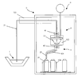
- this sampler for taking a, especially aqueous, Fluids from a fluid tapping point 1 and for metering, filling and schematically storing a fluid sample of the withdrawn fluid shown.
- this sampler comprises a vessel arrangement 2 of Predeterminable lumen, which the guiding and holding the fluid or the Serves fluid sample.
- the sampler can be both a stationary and a mobile one Be a sampler.
- the vessel arrangement 2 of the sampler comprises according to the figure Withdrawal vessel 21 for withdrawing and guiding a first volume of fluid, a metering vessel 22 for receiving a second volume of fluid from first fluid volume and for metering a third fluid volume of the second fluid volume and a distribution vessel 23 for guiding the third fluid volume.
- the vessel assembly 2 includes Operation of a storage vessel 24 for storing the fluid sample to be stored of the third fluid volume.
- Each of these vessels 21, 22, 23, 24 the vessel arrangement 2 can be predetermined by an enveloping wall Form and strength determined and thus in relation to the environment delimited.
- the extraction vessel 21 is tubular and has a inlet-side first and outlet-side second ends.
- the removal vessel 21 is preferably at least in sections as flexible hose, especially made of elastic material.
- Material can all be in samplers for such collection vessels usual materials, e.g. Polyethylene or glass become.
- the removal vessel 21 is at its second end with a first Inlet / outlet opening of the metering vessel 22 connected, as in shown in the figure, preferably at a highest point of the metering vessel 22 or in the vicinity thereof; if necessary, the Inlet / outlet opening also at a lower point of the Dosing vessel 22 may be arranged.
- the metering vessel 22 preferably has one of the inlet / outlet opening outgoing and with one end protruding into its lumen tubular inlet / outlet piece 221 of a predetermined length.
- the inlet / outlet piece 221st usually through an outlet-side section of the removal vessel 21, which is perpendicular from above into the lumen of the metering vessel 22 protrudes, realized.
- the metering vessel 22 is preferably made of glass; but it can also come from any other commonly used for such dosing vessels Material, e.g. Polyethylene.
- the distribution vessel 23 with an inlet-side first end connected.
- the outlet opening is according to the figure preferably at a lowest point of the metering vessel 22; she can, if necessary, also at another point of the metering vessel 22 be arranged.
- the distribution vessel 23 is also like the extraction vessel 21 tubular, in particular elastically deformable in sections. It is shaped and dimensioned so that a through its outlet side End flowing fluid through an inlet opening of the storage vessel 24 can be introduced into this.
- the distribution vessel 23 is preferably pivotable carried out that a fluid flowing through the second end into further, storage vessels spaced apart from the storage vessel 24 can be introduced.
- the Distribution vessel 23 can also have a plurality of ends on the outlet side and be designed so that with several to be filled Storage vessels thus assigned to each of the ends on the outlet side is that the fluid flowing through the ends into each Storage vessel can be introduced.
- the fluid to be taken with the sampler is a fluid, in particular drinking water or waste water, which is to be examined for its chemical and / or biological properties, for example the substances or bacteria carried along.
- Such fluids have a temperature-dependent activity which, after removal, can cause a change in the chemical-biological properties to be examined.
- the higher the fluid temperature, the greater the activity. Therefore, the fluid removed at an instantaneous removal temperature T 1 is stored after the removal at a predeterminable low, especially stationary, storage temperature T L.
- This storage temperature T L is such that the resulting activity is reduced to such an extent that it does not change the fluid sample inadmissibly.
- the removal of the fluid usually takes place at a relatively high removal temperature T 1 , for example 288 K (Kelvin), at which the fluid can have a correspondingly high activity.
- T 1 for example 288 K (Kelvin)
- the sampler therefore also includes one with the vessel arrangement 2 thermally coupled cooling arrangement 3 for cooling the removed Fluids.
- Thermally coupled means that between the cooling arrangement 3 and the vessel arrangement 2, in particular a lumen of the vessel arrangement 2, Temporary differences in temperature can be almost compensated for can.
- the cooling arrangement 3 encloses a first cooling volume of at least predeterminable spatially averaged first cooling temperature T 31, which at least surrounds the storage vessel 24 during operation of the sampler.
- the first cooling volume is through an external, especially thermostatted, Enclosure enclosed, and thus delimited from the outside.
- the wrapping is used for thermal insulation of the first cooling volume and usually also as a support and holding structure for the vessel arrangement 2. You therefore consists on the one hand of heat-insulating material and on the other hand, from mechanically strong construction material.
- the first cooling volume is that shown in the figure Embodiment formed by the lumen of a cold room 311. This can e.g. a mobile cooler or a stationary one Be a cooling chamber.
- the first cooling volume is preferably designed so that it is additionally via the metering vessel 22 and also over part of the Extraction vessel 21 extends. Furthermore, it can be designed so that in addition to the storage vessel 24, there are also others at the same time Storage vessels can be accommodated.
- the sampler further comprises a shut-off arrangement 4, the temporary and sectionally pressure-tight Closing the vessel arrangement 2, in particular the metering vessel 22, serves.
- a first shut-off element on this or on the removal vessel 21 41 of the shut-off arrangement 4 attached. Furthermore is for temporary Closing the outlet opening of the metering vessel 22 on this or on Distribution vessel 23, a second shut-off element 42 of the shut-off arrangement 4 attached.
- shut-off elements 41, 42 manually used, electromechanically or pneumatically driven valves or slides serve, cf. US-A 37 95 347 or US-A 38 80 011.
- the shut-off element is preferably used as one Hose clamp designed, cf. US-A 40 77 263.
- the fluid tapping point 1 can be in any suitable partial volume of the fluid to be withdrawn.
- the fluid is then allowed to flow into the removal vessel 21 communicating with the fluid removal point 1 at a first point in time t 1 and passed on in such a way that it reaches the metering vessel 22 connected to the removal vessel 21 at a second point in time t 2 .
- Samplers of the type described therefore usually instruct one the vessel arrangement 2 connected pressure source 5, which the Generating a static pressure of a predeterminable size in a lumen the vessel arrangement 2, in particular in the lumen of the removal vessel 21 and the Dosing vessel 22, see. also US-A 37 95 347, US-A 38 80 011 or US-A 40 77 263.
- the lumen is between inlet-side and outlet-side end of the with the fluid tapping point 1 communicating extraction vessel 21 a first Differential pressure generated, the inflow of the fluid into the Withdrawal vessel 21 and into the metering vessel 22 connected to it causes.
- the sampler does this with the inlet / outlet opening open and with the outlet opening closed in the lumen of the Metering vessel 22 by means of the pressure source 5, the static pressure reduced at least to the extent that this is then in the removal vessel 21 fluid flowing in against the force of gravity at least one highest Level of the extraction vessel 21 reached, cf. also US-A 40 77 263.
- the fluid is allowed to flow into the metering vessel 22 until this is filled with the second fluid volume.
- This is Usually dimensioned so that a definable first level in the Dosing vessel 22 is reached, which is above the end of the Inlet / outlet piece 221 is located.
- the second pressure difference can e.g. are generated by the fact that the static pressure in the metering vessel 22 by means of the pressure source 5 is increased at least to the extent that this is then in the inlet / outlet piece 221 and in the removal vessel 21 against gravity inflowing fluid at least the highest level of the sampling vessel 21 reached.
- this pressure difference is preferred generates that between the fluid tapping point 1 and the metering vessel 22 a compensation of their static pressures is effected.
- This Compensation can take place at a fluid removal point open to the atmosphere 1 e.g. by simply venting the metering vessel 22 respectively.
- the resulting pressure difference then becomes essentially by that between the end of the inlet / outlet piece 221 and the fluid level existing height difference determined.
- the outlet opening is opened at a third point in time t 3 and the third fluid volume is filled into the storage vessel 24 by means of the distributor vessel 23 or when using a plurality of storage vessels in the divided in the manner described above.
- the fluid sample located in the storage vessel 24 or in the storage vessels is stored after reaching the essentially stationary storage temperature T L with a temperature value of, for example, 277 K (Kelvin) at a time t 4 .
- the storage temperature T L is at most equal to an allowable highest storage temperature of the fluid but at least equal to an allowable lowest storage temperature of the fluid.
- the permissible highest storage temperature is equal to a lowest of the respectively permissible highest or the permissible lowest storage temperature is equal to a highest of the respectively permissible lowest storage temperature of the fluids.
- the cooling temperature T 31 in the operation of the first cooling volume in particular in the case of fluid samples located therein, is always set at most equal to the permissible highest storage temperature and is therefore practically always lower than an ambient temperature outside the first cooling volume.
- the cooling temperature T 31 is usually set by means of an active heat sink which is thermally coupled to the first cooling volume but is not shown, for example by means of a heat pump or a Peltier element. All temperature control or temperature control methods known to the person skilled in the art can serve as setting methods.
- the level of the internal temperature of the vessel arrangement T 2 is also dependent on the level of the cooling temperature T 31 due to heat transfer or heat conduction and due to convection in the vessel arrangement 2.
- the cooling temperature T 31 is set to the storage temperature T L of the fluid.
- an instantaneous initial internal temperature distribution is formed with a corresponding instantaneous initial vessel arrangement internal temperature that is lower than the extraction temperature T 1 .
- the vessel arrangement 2 since the first cooling volume according to the figure, the vessel arrangement 2 only partially encloses, is their internal temperature distribution, esp one not or only partially outside the first cooling volume thermostatted sampling vessel 21 or dosing vessel 22, by a external ambient temperature distribution is influenced accordingly.
- An increase in the cooling rate simultaneously shortens the time until the fluid sample has reached the storage temperature T L and thus the cooling phase ⁇ ta.
- the cooling phase ⁇ ta results from the time difference t 4 -t 1 , which lasts from the start of the withdrawal at the time t 1 until the storage temperature in the fluid sample is reached at the time t 4 .
- the internal vessel arrangement temperature is reduced from the initial internal vessel arrangement temperature to a lower cooling internal vessel arrangement temperature, averaged over the vessel arrangement 2, in particular at time t 1 .
- the fluid is allowed to flow into the vessel arrangement 2.
- the inflowing fluid is then cooled below the removal temperature T 1 on account of the lower cooling internal temperature inside the cooling arrangement. This takes place essentially by heat transfer to or by heat conduction in the wall of the vessel arrangement 2.
- the cooling of the fluid thus begins practically with the inflow into the part enclosed by the first cooling volume 31 and takes place, in particular in the storage vessel 24, for practically until the fluid has assumed a stationary temperature, in particular the storage temperature T L , which corresponds to a stationary internal temperature distribution.
- the lowering and raising of the first cooling temperature T 31 and thus also the cooling of the fluid within the vessel arrangement 2, in particular within the metering vessel 22 or the storage vessel 24, can take place in a regulated and / or time-controlled manner.
- the corresponding regulation or control variables can be determined by corresponding calibration measurements.
- the cooling temperature T 31 can , if necessary, also be set to a lower cooling temperature below 273 K.
- the cooling temperature can only be reduced to such an extent that neither impermissibly high cooling speeds in the fluid are reached nor fluid samples already stored in the first cooling volume 31 are impermissibly undercooled. Therefore, the lowering or the raising of the cooling temperature T 31 may need to be modified by setting the cooling temperature T 31 during the cooling phase ⁇ ta to intermediate temperature values that are higher than the cooling temperature.
- the corresponding intermediate temperature values can also be determined in a suitable manner by appropriate calibration.
- the cooling arrangement 3 comprises a second cooling volume at least partially enclosing the vessel arrangement 2 and having a predeterminable spatially averaged second cooling temperature T 32 , which is formed, in particular, at least in sections within the wall of the vessel arrangement 2 and in the lumen of the vessel arrangement 2 thereby encased is.
- the second cooling volume serves, on the one hand, to expand the coolable lumen of the vessel arrangement 2 in the direction of the fluid removal point 1. On the other hand, it serves to exert a targeted influence on the internal temperature distribution of the vessel arrangement 2 and thus to fine-tune and adjust the internal temperature of the vessel arrangement T 2 during the cooling phase ⁇ ta.
- the second cooling volume is replaced by a first one Cooling element 321 on the extraction vessel 21 for setting a Withdrawal vessel internal temperature, a second cooling element 322 am Dosing vessel 22 for setting a dosing vessel inner temperature third cooling element 323 on the distribution vessel 23 for setting one Tanks inside temperature and a fourth cooling element 324 am Storage vessel 24 for setting the internal temperature of the storage vessel each enclosed in sections, and thus practically in corresponding partial cooling volume divided.
- cooling elements in particular as cooling element 321, can in turn appropriate heat pumps are used.
- the cooling element 321 is designed as a continuous cooler.
- Peltier elements in the cooling elements 321, 322, 323, 324 can be used.
- the second cooling volume 32 can also be achieved by only three, two or by a single one of these cooling elements 321, 322, 323, 324, especially if, as shown in the figure, the second cooling volume 32 preferably at least partially from the first Cooling volume 31 is enclosed.
- the internal temperature of the vessel arrangement T 2 is temporarily raised to the internal temperature of the cooling vessel arrangement by means of one or more of the cooling elements 321, 322, 323 or 324 before the first fluid volume is removed , lowered, so that the internal vessel arrangement temperature T 2 , in particular at time t 1 , is again lower than the initial internal vessel arrangement temperature.
- the fluid is again allowed to flow into the vessel arrangement 2 and thereby cooled to a fluid temperature which is below the removal temperature T 1 .
- the above-described method, in which the first cooling temperature T 31 is reduced can also be used in this embodiment of the invention.
- fluid residues removed from the vessel assembly 2. This is done in a suitable manner e.g. characterized in that when the outlet opening of the metering vessel is closed 22 and with the inlet / outlet opening open at the same time by means of the Pressure source 5 is a static excess pressure in the lumen of the metering vessel 22 and the connected removal vessel 21 is generated. Because of this overpressure are residues in the removal vessel 21 through its first end.
- the metering vessel 22 can also by closing the inlet / outlet opening outlet opening simultaneously opened by means of a in the lumen of the Metering vessel 22 generated excess pressure, the metering vessel itself and the connected distribution vessel 23 freed of fluidic residues become; the latter can then via the second end of the distribution vessel 23 into or out of a suitable vessel of the sampler be directed.
Landscapes
- Life Sciences & Earth Sciences (AREA)
- Hydrology & Water Resources (AREA)
- Physics & Mathematics (AREA)
- Health & Medical Sciences (AREA)
- Chemical & Material Sciences (AREA)
- Analytical Chemistry (AREA)
- Biochemistry (AREA)
- General Health & Medical Sciences (AREA)
- General Physics & Mathematics (AREA)
- Immunology (AREA)
- Pathology (AREA)
- Sampling And Sample Adjustment (AREA)
- Devices That Are Associated With Refrigeration Equipment (AREA)
- Automatic Analysis And Handling Materials Therefor (AREA)
Abstract
Description
- eine Gefäßanordnung
- mit einem rohrförmigen Entnahmegefäß zum Führen eines strömenden Fluids,
- mit einem auslaßseits temporär verschließbaren Dosiergefäß zum Abdosieren der Fluid-Probe vom entnommenen Fluid,
- mit einem Verteilergefäß zum Weiterleiten der Fluid-Probe und
- mit einem Speichergefäß zum Speichern der Fluid-Probe.
- eine Gefäßanordnung von vorgebbarem Lumen mit
- einer über das Lumen räumlich gemittelten Gefäßanordnungs-Innentemperatur
- einem rohrförmigen Entnahmegefäß zum Führen eines strömenden Fluids,
- einem auslaßseits temporär verschließbaren Dosiergefäß zum Abdosieren der Fluid-Probe vom entnommenen Fluid,
- einem Verteilergefäß zum Weiterleiten der Fluid-Probe und
- einem Speichergefäß zum Speichern der Fluid-Probe sowie
- eine mit der Gefäßanordnung thermisch gekoppelte Kühlanordnung zum
Einstellen der Gefäßanordnungs-Innentemperatur, mit
- einem wenigstens das Speichergefäß umhüllenden ersten Kühlvolumen von vorgebbarer erster Kühltemperatur zum Kühlen der Fluid-Probe auf die Lagerungs-Temperatur und
- einem die Gefäßanordnung wenigstens abschnittsweise ummantelnden zweiten Kühlvolumen von vorgebbarer zweiter Kühltemperatur zum Kühlen des entnommenen Fluids unter die Fluid-Entnahmetemperatur.
- eine Gefäßanordnung von vorgebbarem Lumen mit
- einer über das Lumen räumlich gemittelten Gefäßanordnungs-Innentemperatur
- einem rohrförmigen Entnahmegefäß zum Führen eines strömenden Fluids,
- einem auslaßseits temporär verschließbaren Dosiergefäß zum Abdosieren der Fluid-Probe vom entnommenen Fluid,
- einem Verteilergefäß zum Weiterleiten der Fluid-Probe,
- mit einem Speichergefäß zum Speichern der Fluid-Probe, und
- eine mit der Gefäßanordnung thermisch gekoppelte Kühlanordnung zum
Einstellen der Gefäßanordnungs-Innentemperatur mit
- einem wenigstens das Speichergefäß umhüllenden ersten Kühlvolumen von vorgebbarer erster Kühltemperatur zum Kühlen der Fluid-Probe auf die Lagerungs-Temperatur, wobei
- die Gefäßanordnungs-Innentemperatur vor dem Abfüllen eine Anfangs-Gefäßanordnungs-Innentemperatur aufweist, die niedriger als die Entnahme-Temperatur ist, und
- die erste Kühltemperatur vor dem Abfüllen und nach dem Einlagern der Fluid-Probe auf die Lagerungs-Temperatur eingestellt ist,
- die Fluid-Probe wird dadurch abgefüllt, daß
- das Fluid von der Fluid-Entnahmestelle aus durch das Entnahmegefäß hindurch in das auslaßseits verschlossene Dosiergefäß gefördert wird,
- ein vorgebbares Teil-Volumen des Fluids im Dosiergefäß belassen wird,
- das Dosiergefäß auslaßseits geöffnet wird und
- das Teil-Volumen des Fluids durch das Verteilergefäß hindurch in das Speichergefäß einströmen gelassen wird, und
- die Fluid-Probe wird dadurch abgekühlt, daß
- die Gefäßanordnungs-Innentemperatur mittels der Kühlanordnung vor und/oder während des Abfüllens auf eine Abkühlungs-Gefäßanordnungs-Innentemperatur abgesenkt wird, die niedriger als die Anfangs-Gefäßanordnungs-Innentemperatur ist, und
- das Fluid nach dem Einstellen der Abkühlungs-Gefäßanordnungs-Innentemperatur in der Gefäßanordnung (2) geführt und/oder gehalten wird.
- ein am Entnahmegefäß angeordnetes erstes Kühlelement zum Einstellen einer Entnahmegefäß-Innentemperatur und/oder
- ein am Dosiergefäß angeordnetes zweites Kühlelement zum Einstellen einer Dosiergefäß-Innentemperatur und/oder
- ein am Verteilergefäß angeordnetes drittes Kühlelement zum Einstellen einer Speichergefäß-Innentemperatur und/oder
- ein am Speichergefäß angeordnetes viertes Kühlelement zum Einstellen der Speichergefäß-Innentemperatur,
- wobei das jeweilige Kühlelement das zweite Kühlvolumen abschnittsweise ummantelt.
- wird eine Kühlanordnung mit einem die Gefäßanordnung wenigstens abschnittsweise umgebenden zweiten Kühlvolumen von vorgebbarer zweiter Kühltemperatur zum Kühlen des entnommenen Fluids unter die Entnahme-Temperatur verwendet und
- wird die Abkühlungs-Gefäßanordnungs-Innentemperatur vor dem Einströmen des Fluids in das Dosiergefäß durch ein temporäres Einstellen der zweiten Kühltemperatur auf eine zweite Abkühlungs-Temperatur, die niedriger als die Lagerungs-Temperatur ist, eingestellt.
Claims (13)
- Probenehmer zum Abfüllen und Abkühlen einer bei einer vorgebbaren Lagerungs-Temperatur einzulagernden Fluid-Probe eines an einer Fluid-Entnahmestelle (1) entnommenen Fluids, das eine momentane Entnahme-Temperatur aufweist, die größer als die Lagerungs-Temperatur ist, welcher Probenehmer umfaßt:eine Gefäßanordnung (2) von vorgebbarem Lumen miteiner über das Lumen räumlich gemittelten Gefäßanordnungs-Innentemperatureinem rohrförmigen Entnahmegefäß (21) zum Führen eines strömenden Fluids,einem auslaßseits temporär verschließbaren Dosiergefäß (22) zum Abdosieren der Fluid-Probe vom entnommenen Fluid,einem Verteilergefäß (23) zum Weiterleiten der Fluid-Probe undeinem Speichergefäß (24) zum Speichern der Fluid-Probe sowieeine mit der Gefäßanordnung (2) thermisch gekoppelte Kühlanordnung (3) zum Einstellen der Gefäßanordnungs-Innentemperatur, miteinem wenigstens das Speichergefäß (24) umhüllenden ersten Kühlvolumen von vorgebbarer erster Kühltemperatur zum Kühlen der Fluid-Probe auf die Lagerungs-Temperatur undeinem die Gefäßanordnung (2) wenigstens abschnittsweise ummantelnden zweiten Kühlvolumen von vorgebbarer zweiter Kühltemperatur zum Kühlen des entnommenen Fluids unter die Fluid-Entnahmetemperatur.
- Probenehmer nach Anspruch 1, bei dem das zweite Kühlvolumen vom ersten Kühlvolumen wenigstens teilweise umhüllt ist.
- Probenehmer nach Anspruch 1 oder 2, bei dem die Kühlanordnung (3) umfaßt:ein am Entnahmegefäß (21) angeordnetes erstes Kühlelement (321) zum Einstellen einer Entnahmegefäß-Innentemperatur und/oderein am Dosiergefäß (22) angeordnetes zweites Kühlelement (322) zum Einstellen einer Dosiergefäß-Innentemperatur und/oderein am Verteilergefäß (23) angeordnetes drittes Kühlelement (323) zum Einstellen einer Speichergefäß-Innentemperatur und/oderein am Speichergefäß (24) angeordnetes viertes Kühlelement (324) zum Einstellen der Speichergefäß-Innentemperatur,wobei das jeweilige Kühlelement (321, 322, 323, 324) das zweite Kühlvolumen abschnittsweise ummantelt.
- Probenehmer nach Anspruch 3, bei dem das erste Kühlelement (321) ein Durchlaufkühler ist.
- Probenehmer nach Anspruch 3, bei dem wenigstens eines der Kühlelemente (321, 322, 323, 324) ein Peltier-Element umfaßt.
- Probenehmer nach einem der Ansprüche 1 bis 5, bei dem das Dosiergefäß (22) innerhalb des ersten Kühlvolumens angeordnet ist.
- Probenehmer nach Anspruch 6, bei dem das Entnahmegefäß (21) vom ersten Kühlvolumen teilweise umhüllt ist.
- Probenehmer nach einem der Ansprüche 1 bis 7, bei dem die Kühlanordnung (3) einen Kühlraum (311) umfaßt, dessen Lumen das erste Kühlvolumen ist.
- Probenehmer nach einem der Ansprüche 1 bis 8, bei dem das Fluid ein Trinkwasser oder ein Abwasser ist.
- Verfahren zum Abfüllen und Abkühlen einer bei einer vorgebbaren Lagerungs-Temperatur einzulagernden Fluid-Probe eines an einer Fluid-Entnahmestelle (1) entnommenen Fluids, das eine momentane Entnahme-Temperatur aufweist, die größer als die Lagerungs-Temperatur ist, mittels eines Probenehmers, der umfaßt:eine Gefäßanordnung (2) von vorgebbarem Lumen miteiner über das Lumen räumlich gemittelten Gefäßanordnungs-Innentemperatureinem rohrförmigen Entnahmegefäß (21) zum Führen eines strömenden Fluids,einem auslaßseits temporär verschließbaren Dosiergefäß (22) zum Abdosieren der Fluid-Probe vom entnommenen Fluid,einem Verteilergefäß (23) zum Weiterleiten der Fluid-Probe,mit einem Speichergefäß (24) zum Speichern der Fluid-Probe, undeine mit der Gefäßanordnung (2) thermisch gekoppelte Kühlanordnung (3) zum Einstellen der Gefäßanordnungs-Innentemperatur miteinem wenigstens das Speichergefäß (24) umhüllenden ersten Kühlvolumen von vorgebbarer erster Kühltemperatur zum Kühlen der Fluid-Probe auf die Lagerungs-Temperatur, wobeiwelches Verfahren folgende Schritte umfaßt:die Gefäßanordnungs-Innentemperatur vor dem Abfüllen eine Anfangs-Gefäßanordnungs-Innentemperatur aufweist, die niedriger als die Entnahme-Temperatur ist, unddie erste Kühltemperatur vor dem Abfüllen und nach dem Einlagern der Fluid-Probe auf die Lagerungs-Temperatur eingestellt ist,die Fluid-Probe wird dadurch abgefüllt, daßdas Fluid von der Fluid-Entnahmestelle (1) aus durch das Entnahmegefäß (21) hindurch in das auslaßseits verschlossene Dosiergefäß (22) gefördert wird,ein vorgebbares Teil-Volumen des Fluids im Dosiergefäß (22) belassen wird,das Dosiergefäß (22) auslaßseits geöffnet wird unddas Teil-Volumen des Fluids durch das Verteilergefäß (23) hindurch in das Speichergefäß (24) einströmen gelassen wird, unddie Fluid-Probe wird dadurch abgekühlt, daßdie Gefäßanordnungs-Innentemperatur mittels der Kühlanordnung (3) vor und/oder während des Abfüllens auf eine Abkühlungs-Gefäßanordnungs-Innentemperatur abgesenkt wird, die niedriger als die Anfangs-Gefäßanordnungs-Innentemperatur ist, unddas Fluid nach dem Einstellen der Abkühlungs-Gefäßanordnungs-Innentemperatur in der Gefäßanordnung (2) geführt und/oder gehalten wird.
- Verfahren nach Anspruch 10, bei dem die Gefäßanordnungs-Innentemperatur dadurch auf die Abkühlungs-Gefäßanordnungs-Innentemperatur eingestellt wird, daß die erste Kühltemperatur temporär auf eine erste Abkühlungs-Temperatur abgesenkt wird, die niedriger als die Lagerungs-Temperatur ist.
- Verfahren nach Anspruch 10 oder 11,bei dem eine Kühlanordnung (3) mit einem die Gefäßanordnung (2) wenigstens abschnittsweise umgebenden zweiten Kühlvolumen von vorgebbarer zweiter Kühltemperatur zum Kühlen des entnommenen Fluids unter die Entnahme-Temperatur verwendet wird undbei dem die Abkühlungs-Gefäßanordnungs-Innentemperatur vor dem Einströmen des Fluids in das Dosiergefäß (22) durch ein temporäres Einstellen der zweiten Kühltemperatur auf eine zweite Abkühlungs-Temperatur, die niedriger als die Lagerungs-Temperatur ist, eingestellt wird.
- Verfahren nach einem der Ansprüche 10 bis 12, bei dem die Fluid-Probe von einem wäßriges Fluid entnommen wird.
Priority Applications (5)
| Application Number | Priority Date | Filing Date | Title |
|---|---|---|---|
| AT99111313T ATE308744T1 (de) | 1999-06-10 | 1999-06-10 | Probenehmer und verfahren zum abfüllen und abkühlen eines fluids |
| EP99111313A EP1059519B1 (de) | 1999-06-10 | 1999-06-10 | Probenehmer und Verfahren zum Abfüllen und Abkühlen eines Fluids |
| ES99111313T ES2251135T3 (es) | 1999-06-10 | 1999-06-10 | Recogedor de muestras y procedimiento para trasegar y enfriar un fluido. |
| DE59912739T DE59912739D1 (de) | 1999-06-10 | 1999-06-10 | Probenehmer und Verfahren zum Abfüllen und Abkühlen eines Fluids |
| CA002311198A CA2311198C (en) | 1999-06-10 | 2000-06-12 | Sampler and method of dispensing and cooling a fluid |
Applications Claiming Priority (1)
| Application Number | Priority Date | Filing Date | Title |
|---|---|---|---|
| EP99111313A EP1059519B1 (de) | 1999-06-10 | 1999-06-10 | Probenehmer und Verfahren zum Abfüllen und Abkühlen eines Fluids |
Publications (2)
| Publication Number | Publication Date |
|---|---|
| EP1059519A1 true EP1059519A1 (de) | 2000-12-13 |
| EP1059519B1 EP1059519B1 (de) | 2005-11-02 |
Family
ID=8238337
Family Applications (1)
| Application Number | Title | Priority Date | Filing Date |
|---|---|---|---|
| EP99111313A Expired - Lifetime EP1059519B1 (de) | 1999-06-10 | 1999-06-10 | Probenehmer und Verfahren zum Abfüllen und Abkühlen eines Fluids |
Country Status (5)
| Country | Link |
|---|---|
| EP (1) | EP1059519B1 (de) |
| AT (1) | ATE308744T1 (de) |
| CA (1) | CA2311198C (de) |
| DE (1) | DE59912739D1 (de) |
| ES (1) | ES2251135T3 (de) |
Cited By (5)
| Publication number | Priority date | Publication date | Assignee | Title |
|---|---|---|---|---|
| EP1209459A1 (de) * | 2000-11-24 | 2002-05-29 | ENDRESS + HAUSER WETZER GmbH + Co. KG | Probenehmer und Verfahren zum Abfüllen und Abkühlen eines Fluids |
| WO2003076906A1 (de) * | 2002-03-12 | 2003-09-18 | Endress + Hauser Wetzer Gmbh + Co. Kg | Dosiervorrichtung für einen probenehmer |
| WO2003081525A1 (de) * | 2002-03-21 | 2003-10-02 | Endress + Hauser Wetzer Gmbh + Co. Kg | Vorrichtung zur identifizierung eines probennehmerbehälters |
| WO2007057432A1 (de) * | 2005-11-17 | 2007-05-24 | Endress + Hauser Conducta Gesellschaft für Mess- und Regeltechnik mbH + Co. KG | Probenwehmer mit einer separaten temperiereinheit |
| CN110376020A (zh) * | 2019-07-05 | 2019-10-25 | 江苏省镔鑫钢铁集团有限公司 | 一种高炉渣定量取样装置及取样方法 |
Families Citing this family (1)
| Publication number | Priority date | Publication date | Assignee | Title |
|---|---|---|---|---|
| NL2035937B1 (en) * | 2023-10-02 | 2025-04-10 | Bvh B V | Automatic fluid sampler |
Citations (6)
| Publication number | Priority date | Publication date | Assignee | Title |
|---|---|---|---|---|
| US3795347A (en) * | 1972-02-03 | 1974-03-05 | E Singer | Power purged liquid sampler |
| US3880011A (en) * | 1974-02-14 | 1975-04-29 | Harsco Corp | Automatic sampler |
| US3897687A (en) * | 1973-08-03 | 1975-08-05 | Robert H Burberry | Composite sampler |
| US4077263A (en) * | 1975-07-30 | 1978-03-07 | Brailsford Harrison D | Vacuum operated sampler |
| FR2647213A1 (fr) * | 1989-05-22 | 1990-11-23 | Centre Nat Rech Scient | Systeme echantillonneur automatique d'un liquide biologique a prelevement sterile |
| US5587926A (en) * | 1989-12-22 | 1996-12-24 | American Sigma, Inc. | Refrigerated fluid sampling apparatus and method with variable volume sampling system |
-
1999
- 1999-06-10 EP EP99111313A patent/EP1059519B1/de not_active Expired - Lifetime
- 1999-06-10 AT AT99111313T patent/ATE308744T1/de not_active IP Right Cessation
- 1999-06-10 ES ES99111313T patent/ES2251135T3/es not_active Expired - Lifetime
- 1999-06-10 DE DE59912739T patent/DE59912739D1/de not_active Expired - Lifetime
-
2000
- 2000-06-12 CA CA002311198A patent/CA2311198C/en not_active Expired - Fee Related
Patent Citations (6)
| Publication number | Priority date | Publication date | Assignee | Title |
|---|---|---|---|---|
| US3795347A (en) * | 1972-02-03 | 1974-03-05 | E Singer | Power purged liquid sampler |
| US3897687A (en) * | 1973-08-03 | 1975-08-05 | Robert H Burberry | Composite sampler |
| US3880011A (en) * | 1974-02-14 | 1975-04-29 | Harsco Corp | Automatic sampler |
| US4077263A (en) * | 1975-07-30 | 1978-03-07 | Brailsford Harrison D | Vacuum operated sampler |
| FR2647213A1 (fr) * | 1989-05-22 | 1990-11-23 | Centre Nat Rech Scient | Systeme echantillonneur automatique d'un liquide biologique a prelevement sterile |
| US5587926A (en) * | 1989-12-22 | 1996-12-24 | American Sigma, Inc. | Refrigerated fluid sampling apparatus and method with variable volume sampling system |
Cited By (7)
| Publication number | Priority date | Publication date | Assignee | Title |
|---|---|---|---|---|
| EP1209459A1 (de) * | 2000-11-24 | 2002-05-29 | ENDRESS + HAUSER WETZER GmbH + Co. KG | Probenehmer und Verfahren zum Abfüllen und Abkühlen eines Fluids |
| WO2003076906A1 (de) * | 2002-03-12 | 2003-09-18 | Endress + Hauser Wetzer Gmbh + Co. Kg | Dosiervorrichtung für einen probenehmer |
| WO2003081525A1 (de) * | 2002-03-21 | 2003-10-02 | Endress + Hauser Wetzer Gmbh + Co. Kg | Vorrichtung zur identifizierung eines probennehmerbehälters |
| WO2007057432A1 (de) * | 2005-11-17 | 2007-05-24 | Endress + Hauser Conducta Gesellschaft für Mess- und Regeltechnik mbH + Co. KG | Probenwehmer mit einer separaten temperiereinheit |
| US8347742B2 (en) | 2005-11-17 | 2013-01-08 | Endress + Hauser Conducta Gesellschaft für Mess- und Regeltechnik mbH + Co. KG | Sampler |
| CN110376020A (zh) * | 2019-07-05 | 2019-10-25 | 江苏省镔鑫钢铁集团有限公司 | 一种高炉渣定量取样装置及取样方法 |
| CN110376020B (zh) * | 2019-07-05 | 2024-05-28 | 江苏省镔鑫钢铁集团有限公司 | 一种高炉渣定量取样装置及取样方法 |
Also Published As
| Publication number | Publication date |
|---|---|
| ATE308744T1 (de) | 2005-11-15 |
| CA2311198C (en) | 2003-03-18 |
| DE59912739D1 (de) | 2005-12-08 |
| CA2311198A1 (en) | 2000-12-10 |
| EP1059519B1 (de) | 2005-11-02 |
| ES2251135T3 (es) | 2006-04-16 |
Similar Documents
| Publication | Publication Date | Title |
|---|---|---|
| DE69626179T2 (de) | Vorrichtung zur Regelung des Füllstandes einer kryogenen Flüssigkeit | |
| DE60020244T2 (de) | Tiefstemperaturlagervorrichtung | |
| EP0310591A1 (de) | Verfahren zum Züchten von homogenen Kristallen und Vorrichtung zur Durchführung des Verfahrens | |
| EP1059519B1 (de) | Probenehmer und Verfahren zum Abfüllen und Abkühlen eines Fluids | |
| DE2752284C3 (de) | Vorrichtung zur Entnahme von Proben aus einem Behälter oder einer Leitung | |
| EP0226118A2 (de) | Behälter für aggressive Flüssigkeiten | |
| EP3234537B1 (de) | Vorrichtung und verfahren zur durchführung einer dichtheitsprüfung an brennstabkapseln | |
| DE102008044292A1 (de) | Verfahren zum Entkeimen von Flüssigkeiten und Flüssigkeitsentkeimungsvorrichtung | |
| EP1209459A1 (de) | Probenehmer und Verfahren zum Abfüllen und Abkühlen eines Fluids | |
| DE3040268C2 (de) | ||
| DE3430471C1 (de) | Vorrichtung zur Entnahme von fluessigem Stickstoff aus einer Einrichtung zur Kryofixation und/oder Kryopraeparation zum Zwecke des Kryotransfers gefrorener Proben | |
| EP0550523B1 (de) | Verfahren und vorrichtung zur probengewinnung und probenhandhabung | |
| EP0580881A1 (de) | Vorrichtung zur Entgasung von Flüssigkeiten in Flüssigkeitskreislaufsystemen | |
| DE2054054C3 (de) | Vorrichtung zur Zuführung von Kältemittel in Kryostaten | |
| DE4308720A1 (de) | Meßgerät zur Bestimmung von Bodeneigenschaften | |
| DE3425412A1 (de) | Verfahren und vorrichtung zur steuerung von sterilisations- oder desinfektionsprozessen | |
| DE4308054C2 (de) | Entgasungseinrichtung | |
| DE1297288B (de) | Verfahren und Vorrichtung zum Sterilisieren von Fluessigkeiten in geschlossenen Behaeltern mit Gaseinschluss | |
| DE1922514C3 (de) | Einrichtung zur Kälteerzeugung | |
| DE673297C (de) | Zellenheisshalter | |
| DE260954C (de) | ||
| DE876476C (de) | Vorrichtung zur analytischen Untersuchung wasserdampffluechtiger Stoffe | |
| DE19619257C2 (de) | Herstellung von stabilen Trockeneis-Formstücken und Vorrichtung zum Ausführen | |
| DE3303891A1 (de) | Demonstrationsapparatur zur qualitativen und quantitativen bestaetigung der gasgesetze | |
| AT271247B (de) | Vorrichtung zur Erzielung einer Abgabe gashältiger Getränke, insbesondere von Bier |
Legal Events
| Date | Code | Title | Description |
|---|---|---|---|
| PUAI | Public reference made under article 153(3) epc to a published international application that has entered the european phase |
Free format text: ORIGINAL CODE: 0009012 |
|
| AK | Designated contracting states |
Kind code of ref document: A1 Designated state(s): AT BE CH DE DK ES FR GB IT LI NL SE |
|
| AX | Request for extension of the european patent |
Free format text: AL;LT;LV;MK;RO;SI |
|
| 17P | Request for examination filed |
Effective date: 20010613 |
|
| AKX | Designation fees paid |
Free format text: AT BE CH DE DK ES FR LI |
|
| RBV | Designated contracting states (corrected) |
Designated state(s): AT BE CH DE DK ES FR GB IT LI NL SE |
|
| GRAP | Despatch of communication of intention to grant a patent |
Free format text: ORIGINAL CODE: EPIDOSNIGR1 |
|
| GRAS | Grant fee paid |
Free format text: ORIGINAL CODE: EPIDOSNIGR3 |
|
| GRAA | (expected) grant |
Free format text: ORIGINAL CODE: 0009210 |
|
| AK | Designated contracting states |
Kind code of ref document: B1 Designated state(s): AT BE CH DE DK ES FR GB IT LI NL SE |
|
| REG | Reference to a national code |
Ref country code: GB Ref legal event code: FG4D Free format text: NOT ENGLISH |
|
| REG | Reference to a national code |
Ref country code: CH Ref legal event code: EP |
|
| REF | Corresponds to: |
Ref document number: 59912739 Country of ref document: DE Date of ref document: 20051208 Kind code of ref document: P |
|
| GBT | Gb: translation of ep patent filed (gb section 77(6)(a)/1977) |
Effective date: 20051222 |
|
| PG25 | Lapsed in a contracting state [announced via postgrant information from national office to epo] |
Ref country code: SE Free format text: LAPSE BECAUSE OF FAILURE TO SUBMIT A TRANSLATION OF THE DESCRIPTION OR TO PAY THE FEE WITHIN THE PRESCRIBED TIME-LIMIT Effective date: 20060202 Ref country code: DK Free format text: LAPSE BECAUSE OF FAILURE TO SUBMIT A TRANSLATION OF THE DESCRIPTION OR TO PAY THE FEE WITHIN THE PRESCRIBED TIME-LIMIT Effective date: 20060202 |
|
| REG | Reference to a national code |
Ref country code: ES Ref legal event code: FG2A Ref document number: 2251135 Country of ref document: ES Kind code of ref document: T3 |
|
| ET | Fr: translation filed | ||
| PG25 | Lapsed in a contracting state [announced via postgrant information from national office to epo] |
Ref country code: BE Free format text: LAPSE BECAUSE OF NON-PAYMENT OF DUE FEES Effective date: 20060630 |
|
| PLBE | No opposition filed within time limit |
Free format text: ORIGINAL CODE: 0009261 |
|
| STAA | Information on the status of an ep patent application or granted ep patent |
Free format text: STATUS: NO OPPOSITION FILED WITHIN TIME LIMIT |
|
| 26N | No opposition filed |
Effective date: 20060803 |
|
| BERE | Be: lapsed |
Owner name: ENDRESS + HAUSER WETZER G.M.B.H. + CO. KG Effective date: 20060630 |
|
| PGFP | Annual fee paid to national office [announced via postgrant information from national office to epo] |
Ref country code: CH Payment date: 20080613 Year of fee payment: 10 |
|
| PGFP | Annual fee paid to national office [announced via postgrant information from national office to epo] |
Ref country code: AT Payment date: 20080616 Year of fee payment: 10 |
|
| PGFP | Annual fee paid to national office [announced via postgrant information from national office to epo] |
Ref country code: NL Payment date: 20080618 Year of fee payment: 10 |
|
| PGFP | Annual fee paid to national office [announced via postgrant information from national office to epo] |
Ref country code: GB Payment date: 20080620 Year of fee payment: 10 |
|
| REG | Reference to a national code |
Ref country code: CH Ref legal event code: PL |
|
| GBPC | Gb: european patent ceased through non-payment of renewal fee |
Effective date: 20090610 |
|
| NLV4 | Nl: lapsed or anulled due to non-payment of the annual fee |
Effective date: 20100101 |
|
| PG25 | Lapsed in a contracting state [announced via postgrant information from national office to epo] |
Ref country code: LI Free format text: LAPSE BECAUSE OF NON-PAYMENT OF DUE FEES Effective date: 20090630 Ref country code: CH Free format text: LAPSE BECAUSE OF NON-PAYMENT OF DUE FEES Effective date: 20090630 |
|
| PG25 | Lapsed in a contracting state [announced via postgrant information from national office to epo] |
Ref country code: GB Free format text: LAPSE BECAUSE OF NON-PAYMENT OF DUE FEES Effective date: 20090610 |
|
| PG25 | Lapsed in a contracting state [announced via postgrant information from national office to epo] |
Ref country code: AT Free format text: LAPSE BECAUSE OF NON-PAYMENT OF DUE FEES Effective date: 20090610 |
|
| PG25 | Lapsed in a contracting state [announced via postgrant information from national office to epo] |
Ref country code: NL Free format text: LAPSE BECAUSE OF NON-PAYMENT OF DUE FEES Effective date: 20100101 |
|
| PGFP | Annual fee paid to national office [announced via postgrant information from national office to epo] |
Ref country code: FR Payment date: 20100706 Year of fee payment: 12 Ref country code: ES Payment date: 20100625 Year of fee payment: 12 |
|
| PGFP | Annual fee paid to national office [announced via postgrant information from national office to epo] |
Ref country code: IT Payment date: 20100625 Year of fee payment: 12 |
|
| PGFP | Annual fee paid to national office [announced via postgrant information from national office to epo] |
Ref country code: DE Payment date: 20100625 Year of fee payment: 12 |
|
| PG25 | Lapsed in a contracting state [announced via postgrant information from national office to epo] |
Ref country code: IT Free format text: LAPSE BECAUSE OF NON-PAYMENT OF DUE FEES Effective date: 20110610 |
|
| REG | Reference to a national code |
Ref country code: FR Ref legal event code: ST Effective date: 20120229 |
|
| REG | Reference to a national code |
Ref country code: DE Ref legal event code: R119 Ref document number: 59912739 Country of ref document: DE Effective date: 20120103 |
|
| PG25 | Lapsed in a contracting state [announced via postgrant information from national office to epo] |
Ref country code: FR Free format text: LAPSE BECAUSE OF NON-PAYMENT OF DUE FEES Effective date: 20110630 Ref country code: DE Free format text: LAPSE BECAUSE OF NON-PAYMENT OF DUE FEES Effective date: 20120103 |
|
| REG | Reference to a national code |
Ref country code: ES Ref legal event code: FD2A Effective date: 20121207 |
|
| PG25 | Lapsed in a contracting state [announced via postgrant information from national office to epo] |
Ref country code: ES Free format text: LAPSE BECAUSE OF NON-PAYMENT OF DUE FEES Effective date: 20110611 |