EP1059548A2 - Faseroptische Kabeleinheiten - Google Patents
Faseroptische Kabeleinheiten Download PDFInfo
- Publication number
- EP1059548A2 EP1059548A2 EP00201994A EP00201994A EP1059548A2 EP 1059548 A2 EP1059548 A2 EP 1059548A2 EP 00201994 A EP00201994 A EP 00201994A EP 00201994 A EP00201994 A EP 00201994A EP 1059548 A2 EP1059548 A2 EP 1059548A2
- Authority
- EP
- European Patent Office
- Prior art keywords
- cable
- buffer
- zip cord
- cord cable
- zip
- Prior art date
- Legal status (The legal status is an assumption and is not a legal conclusion. Google has not performed a legal analysis and makes no representation as to the accuracy of the status listed.)
- Withdrawn
Links
- 239000000835 fiber Substances 0.000 title abstract description 40
- 239000013307 optical fiber Substances 0.000 claims abstract description 26
- 239000004020 conductor Substances 0.000 claims description 9
- XLYOFNOQVPJJNP-UHFFFAOYSA-N water Substances O XLYOFNOQVPJJNP-UHFFFAOYSA-N 0.000 claims description 9
- 230000005540 biological transmission Effects 0.000 claims description 8
- 230000000903 blocking effect Effects 0.000 claims description 5
- 239000000126 substance Substances 0.000 claims description 3
- 239000002131 composite material Substances 0.000 abstract description 11
- 239000000463 material Substances 0.000 description 8
- 239000000779 smoke Substances 0.000 description 7
- 229920001169 thermoplastic Polymers 0.000 description 7
- 239000004416 thermosoftening plastic Substances 0.000 description 7
- 238000000576 coating method Methods 0.000 description 6
- -1 for example Substances 0.000 description 6
- 230000003287 optical effect Effects 0.000 description 5
- 239000000499 gel Substances 0.000 description 4
- 239000004519 grease Substances 0.000 description 4
- 239000000843 powder Substances 0.000 description 4
- RNFJDJUURJAICM-UHFFFAOYSA-N 2,2,4,4,6,6-hexaphenoxy-1,3,5-triaza-2$l^{5},4$l^{5},6$l^{5}-triphosphacyclohexa-1,3,5-triene Chemical compound N=1P(OC=2C=CC=CC=2)(OC=2C=CC=CC=2)=NP(OC=2C=CC=CC=2)(OC=2C=CC=CC=2)=NP=1(OC=1C=CC=CC=1)OC1=CC=CC=C1 RNFJDJUURJAICM-UHFFFAOYSA-N 0.000 description 3
- 239000002033 PVDF binder Substances 0.000 description 3
- 239000004698 Polyethylene Substances 0.000 description 3
- 239000004760 aramid Substances 0.000 description 3
- 239000011248 coating agent Substances 0.000 description 3
- 239000003063 flame retardant Substances 0.000 description 3
- 239000011521 glass Substances 0.000 description 3
- 239000004800 polyvinyl chloride Substances 0.000 description 3
- 229920002981 polyvinylidene fluoride Polymers 0.000 description 3
- 229920003235 aromatic polyamide Polymers 0.000 description 2
- 238000004040 coloring Methods 0.000 description 2
- KAATUXNTWXVJKI-UHFFFAOYSA-N cypermethrin Chemical compound CC1(C)C(C=C(Cl)Cl)C1C(=O)OC(C#N)C1=CC=CC(OC=2C=CC=CC=2)=C1 KAATUXNTWXVJKI-UHFFFAOYSA-N 0.000 description 2
- 239000011152 fibreglass Substances 0.000 description 2
- 238000003780 insertion Methods 0.000 description 2
- 230000037431 insertion Effects 0.000 description 2
- 238000000034 method Methods 0.000 description 2
- 239000000203 mixture Substances 0.000 description 2
- 229920000728 polyester Polymers 0.000 description 2
- 229920000573 polyethylene Polymers 0.000 description 2
- 229920000915 polyvinyl chloride Polymers 0.000 description 2
- 239000012815 thermoplastic material Substances 0.000 description 2
- NIXOWILDQLNWCW-UHFFFAOYSA-M Acrylate Chemical compound [O-]C(=O)C=C NIXOWILDQLNWCW-UHFFFAOYSA-M 0.000 description 1
- 239000004677 Nylon Substances 0.000 description 1
- 239000004743 Polypropylene Substances 0.000 description 1
- 108010001267 Protein Subunits Proteins 0.000 description 1
- 229910000831 Steel Inorganic materials 0.000 description 1
- 239000004809 Teflon Substances 0.000 description 1
- 229920006362 Teflon® Polymers 0.000 description 1
- 239000000654 additive Substances 0.000 description 1
- 229920006231 aramid fiber Polymers 0.000 description 1
- QVGXLLKOCUKJST-UHFFFAOYSA-N atomic oxygen Chemical compound [O] QVGXLLKOCUKJST-UHFFFAOYSA-N 0.000 description 1
- 230000003139 buffering effect Effects 0.000 description 1
- 239000003086 colorant Substances 0.000 description 1
- 150000001875 compounds Chemical class 0.000 description 1
- 230000006835 compression Effects 0.000 description 1
- 238000007906 compression Methods 0.000 description 1
- 238000013461 design Methods 0.000 description 1
- 238000011161 development Methods 0.000 description 1
- FPAFDBFIGPHWGO-UHFFFAOYSA-N dioxosilane;oxomagnesium;hydrate Chemical compound O.[Mg]=O.[Mg]=O.[Mg]=O.O=[Si]=O.O=[Si]=O.O=[Si]=O.O=[Si]=O FPAFDBFIGPHWGO-UHFFFAOYSA-N 0.000 description 1
- 238000009826 distribution Methods 0.000 description 1
- 230000002708 enhancing effect Effects 0.000 description 1
- 238000001125 extrusion Methods 0.000 description 1
- 239000011151 fibre-reinforced plastic Substances 0.000 description 1
- 239000000945 filler Substances 0.000 description 1
- 229920002313 fluoropolymer Polymers 0.000 description 1
- 229910052736 halogen Inorganic materials 0.000 description 1
- 150000002367 halogens Chemical class 0.000 description 1
- 238000009863 impact test Methods 0.000 description 1
- 238000001746 injection moulding Methods 0.000 description 1
- 238000004519 manufacturing process Methods 0.000 description 1
- 239000011159 matrix material Substances 0.000 description 1
- 239000002184 metal Substances 0.000 description 1
- 238000012986 modification Methods 0.000 description 1
- 230000004048 modification Effects 0.000 description 1
- 229920001778 nylon Polymers 0.000 description 1
- 229910052760 oxygen Inorganic materials 0.000 description 1
- 239000001301 oxygen Substances 0.000 description 1
- 238000012856 packing Methods 0.000 description 1
- 230000000737 periodic effect Effects 0.000 description 1
- 239000004033 plastic Substances 0.000 description 1
- 229920003023 plastic Polymers 0.000 description 1
- 229920001200 poly(ethylene-vinyl acetate) Polymers 0.000 description 1
- 229920000098 polyolefin Polymers 0.000 description 1
- 229920001155 polypropylene Polymers 0.000 description 1
- 230000005855 radiation Effects 0.000 description 1
- 238000009877 rendering Methods 0.000 description 1
- 239000011347 resin Substances 0.000 description 1
- 229920005989 resin Polymers 0.000 description 1
- 239000010959 steel Substances 0.000 description 1
- 238000012360 testing method Methods 0.000 description 1
- BFKJFAAPBSQJPD-UHFFFAOYSA-N tetrafluoroethene Chemical compound FC(F)=C(F)F BFKJFAAPBSQJPD-UHFFFAOYSA-N 0.000 description 1
Images

Classifications
-
- G—PHYSICS
- G02—OPTICS
- G02B—OPTICAL ELEMENTS, SYSTEMS OR APPARATUS
- G02B6/00—Light guides; Structural details of arrangements comprising light guides and other optical elements, e.g. couplings
- G02B6/44—Mechanical structures for providing tensile strength and external protection for fibres, e.g. optical transmission cables
- G02B6/4401—Optical cables
- G02B6/4429—Means specially adapted for strengthening or protecting the cables
- G02B6/443—Protective covering
- G02B6/4431—Protective covering with provision in the protective covering, e.g. weak line, for gaining access to one or more fibres, e.g. for branching or tapping
-
- G—PHYSICS
- G02—OPTICS
- G02B—OPTICAL ELEMENTS, SYSTEMS OR APPARATUS
- G02B6/00—Light guides; Structural details of arrangements comprising light guides and other optical elements, e.g. couplings
- G02B6/44—Mechanical structures for providing tensile strength and external protection for fibres, e.g. optical transmission cables
- G02B6/4401—Optical cables
- G02B6/441—Optical cables built up from sub-bundles
Definitions
- the present invention relates to cables having at least one optical fiber therein.
- Conventional fiber optic cables include optical fibers that conduct light that is used to transmit voice, video, and/or data information.
- Conventional fiber optic zip cord cables comprise two sections that are joined by a frangible web, and are typically used in indoor environments and have the advantages of large bandwidth and low power loss.
- a composite cable includes an optical transmission component combined with at least one electronic/electrical transmission component. The advantages of electronic/electrical transmission components include low cost and straightforward termination procedures.
- Typical applications for fiber optic zip cord and composite cables include fiber-to-the-curb (FTTC), fiber-to-the-home (FTTH), fiber-to-the-desk (FTTD), plenum, riser, and local area networks (LANs).
- FTTC fiber-to-the-curb
- FTTH fiber-to-the-home
- FTTD fiber-to-the-desk
- LANs local area networks
- zip cord and composite cables can be used to, for example, interconnect optical devices and/or hardware, computers, modems, and telephones.
- Conventional composite cables can include a row of optical fibers and a separate row of electrical conductors.
- US-A-5039195 discloses a composite cable with two distinct cable units.
- a first cable unit includes optical fiber sub-units connected to strength members by a common jacket having interconnecting web sections.
- a second cable unit includes metal conductors connected by a common jacket having interconnecting web sections. Both cable units are surrounded by a cable jacket.
- a composite cable can include a combination of loose-buffered optical fibers and electrical conductors in a common jacket.
- the common jacket defines a flat structure including box-shaped sub-units, apparently formed by an injection molding process, with twisted electrical leads and optical fibers disposed in buffer tubes.
- the cable is designed to be separated into the box-shaped sub-units for connectorization/termination.
- the present invention provides a zip cord cable having at least two cords with respective jackets attached by a frangible web.
- At least one of the cords includes at least one buffer unit, the buffer unit comprises at least two optical fibers in a generally tight buffer layer, and a layer of filaments generally surrounds the buffer layer.
- the cords can each include optical transmission components.
- at least one of said cords can include an electrical transmission component, for example, a twisted pair of conductors.
- the filaments can be strength members that can include a water blocking substance.
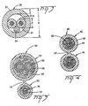
- Unitized fiber optic cable 10 includes subunit cables 20 that may be stranded about a central member 12 and surrounded by a jacket 14.
- Subunit cable 20 can include respective fiber optic and/or composite zip cord cables 40,50 ( Figures 4-5).
- Zip cord cables 40,50 can include at least one buffer unit 30 ( Figure 3).
- Central member 12 can include a suitable thermoplastic layer over a steel wire, for example, a flame/smoke suppressant thermoplastic, or it may include a glass or a fiber reinforced member.
- Jacket 14 can be a flame/smoke retardant thermoplastic, for example, polyvinylchloride (PVC).
- jacket 14 may be formed of a plenum grade flame retarded PVC (FRPVC) having flame retardant and/or smoke suppressant type additives, as disclosed in US-A-5698323 incorporated by reference herein.
- FRPVC plenum grade flame retarded PVC
- jacket 14 may include a fluoroplastic, e.g., polyvinylidene fluoride (PVDF), a fluoro-compound as disclosed in US-A-4963609 incorporated by reference herein, or blends of FRPVC/PVDF may be used.
- PVDF polyvinylidene fluoride
- FRPE flame retardant polyethylene
- Unitized fiber optic cable 10 can include one or more filler rods 16 formed of, for example, a flame/smoke suppressant thermoplastic material or a glass or fiber reinforced rod.
- unitized fiber optic cable 10 will include a ripcord 18.
- Subunit cable 20 can include a dielectric central member 22 about which at least one fiber optic zip cord 40 ( Figure 4) and/or composite zip cord cable ( Figure 5) is disposed.
- a layer of dielectric strength members 24 can surround cables 40,50, and a jacket 28 can surround strength members 24.
- cable 20 may include a ripcord 26 between strength members 24 and jacket 28.
- Central member 22 may be a relatively stiff fiber or glass reinforced plastic rod that may include a plastic overcoating.
- central member 22 may be a flexible bundle of strength members, e.g., aramid yarn or fiber glass that may include a thermoplastic overcoating.
- Strength members 24 are preferably longitudinally disposed or stranded about cables 20.
- Jacket 28 can be made of the same materials that jacket 14 is made of, or it can be made of any other suitable thermoplastic material.
- Each zip cord cable 40,50 includes at least one buffer unit 30 (Figure 3).
- Buffer unit 30 includes at least two optical fibers 31 that can be single mode, multi-mode, and/or multi-core optical fibers. Each optical fiber can have a glass core, and inner and outer primary thermoplastic coatings surrounded by a coloring layer 31a. Layer 31a can have a nominal outside diameter d, for example, of about 260 ⁇ m ( ⁇ 20 ⁇ m) ( Figure 3). A tight buffer jacket coating over the coloring layer is not altogether necessary, but in some applications it may be desired.
- Buffer unit 30 can include a buffer layer, for example, a generally round buffer tube 32 with a nominal wall thickness t of about 170 ⁇ m, and a maximum wall thickness of about 240 ⁇ m ( Figure 3) .
- Buffer tube 32 can be dimensioned to include, for example, a nominal inside diameter roughly equal to an integer multiple of a nominal outside diameter of optical fiber 31.
- the inside diameter of buffer tube 32 can be about twice nominal fiber diameter d.
- buffer tube 32 can include a nominal outside diameter D, for example, of about 900 ⁇ m ( ⁇ 100 ⁇ m).
- the dimensions of tube 32 can be such that portions of the outer surfaces of each optical fiber 31 will touch each other, and other portions will touch buffer tube 32, in a manner that permits sliding contact therebetween.
- tube 32 is dimensioned so that fibers 31 are held tight enough to inhibit twisting and/or cross-overs of the optical fibers.
- Buffer unit 30 may comprise other configurations as well, for example, as disclosed in U.S. Patent application Serial. No. 09/282,343 incorporated by reference herein, a copy of which is being filed with this application.
- Buffer tubes 32 can be formed of a non-halogenated thermoplastic with low smoke evolution characteristics having, for example, a suitable limiting oxygen index.
- the buffer tube material can be a flame retarded, non-halogenated polyolefin (FRPO), e.g., a flame retarded polyethylene (FRPE) or a flame retarded polypropylene (FRPP).
- FRPE flame retarded polyolefin
- FRPE flame retarded polyethylene
- FRPP flame retarded polypropylene
- FRPE is typically not a plenum grade material as it has little or no resistance to flame spread above certain temperatures, but it has low smoke evolution characteristics.
- Buffer unit 30 can include a waterblocking substance, e.g., a superabsorbent powder, a filling compound such as a gel or grease, and/or a waterblocking yarn 34.
- a waterblocking substance e.g., a superabsorbent powder, a filling compound such as a gel or grease, and/or a waterblocking yarn 34.
- Buffer unit 30 offers the advantages of ease of handling and connectorization, for example, connectorization to multi-fiber connectors. More specifically, a buffer unit 30 can be provided for each fiber insertion aperture of the multi-fiber connector. Multiple fibers 31 in a nominal 900 ⁇ m OD buffer tube 31 reduces the bulk of material at the back of the multi-fiber connector thereby rendering the connectorization, and handling and routing of optical fibers less difficult. In addition, fiber optic cables according to the present invention have a high packing density, especially where second and third layers of cables 20 are added.
- At least one buffer unit 30 can be included as a component in zip cord cables 40,50 ( Figures 4-5). More particularly, zip cord cable 40 can include two optical cords 42 connected by a frangible web 43. Each cord 42 can include a jacket 46 and a layer of filaments, for example, strength members 44 that generally surround a respective buffer unit 30. The OD of cord 42 can be, for example, about 3.0 mm or less.
- Composite zip cord cable 50 can include a fiber optic cord 52 connected to an electronic/electrical cord 54 by a frangible web 53. Each cord 52,54 can include a jacket 56 and a layer of filaments, for example, strength members 57. Electrical cord 54 includes at least one electrically conductive member 55, for example, a twisted pair of electrical conductors.
- Strength members 44,57 can comprise, for example, aramid strength members with or without a coating of water blocking grease, or a superabsorbent powder or matrix coating.
- Jackets 46,56 can be formed of, for example, PVC, FRPE, PE, or a UV curable resin, e.g., acrylate.
- Webs 43,53 are sized to be ripped manually or with tools as the cords are separated.
- Manufacture of cables 40,50 of the present invention can be accomplished by passing the optical and electrical components through an extruder and extruding jackets 46,56 therearound.
- filaments 44,57 can be coated with a talc powder to prevent the sticking of jackets 46,56 to the filaments.
- the die profile can be shaped so that cords 42,52,54 have a generally round cross section, or the die can be configured to define other cross sectional shapes as well.
- the die profile forms webs 43,53 with thicknesses that are generally less than the outside diameter (OD) of at least one of the cords. Webs 43,53 can space cords 42,52,54 apart a suitable distance for easy separability thereof. The respective outside diameters of cords 42,52,54 need not be equal.
- Fiber optic cables made according to the present invention can be suitable for use in plenum, riser, LSZH, and indoor/outdoor applications.
- fiber optic cables made according to the present invention can advantageously meet ICEA-596 requirements with respect to mechanical tests, for example, tensile, compression, cycle flex, and impact tests.
- the wall thicknesses of jackets 46,56 may be increased to produce heavy-duty, crush resistant cables.
- Cords 42,52 can include more than one buffer unit 30, and cord 54 can include at least one buffer unit 30.
- the quality and number of filaments 44,57 may be varied to produce high strength cables.
- Indoor/outdoor cables made in accordance with the present invention could include UV radiation resistant as well as flame retardant materials.
- one or more means to prevent water intrusion would be incorporated into the cable, for example: a water blocking grease or gel; water swellable threads, tape, or powder; and/or water swellable coatings applied between the jacket and buffer unit. Additional water blocking capabilities can be included between the buffer and the optical fibers, for example, greases, gels, or water swellable powders, threads, or coatings.
- the present invention includes zip cord cables 40,50 defining the core of a fiber optic cable, e.g., for single tube or interconnect/jumper cables.
- buffer units 30 may include more than two optical fibers, and one or more strength filaments, e.g., aramid fibers, inside the buffer layer.
- tubes 32 can comprise multiple layers of thermoplastics, for example, as disclosed in US-A-4664472 incorporated by reference herein.
- Optical fibers 31 and/or the inner surface of tubes 32 can include a friction-reducing interfacial layer, for example, TEFLON and/or a gel or grease composition, for enhancing sliding contact between optical fibers 31 and buffer tube 32.
- electrical conductor 55 can be any suitable electrical transmission component or a combination of electrical components, e.g., a co-axial cable or a non-twisted conductor.
- one or more periodic refractive indices can be written into the fiber before buffering, for example, as disclosed in US-A-4725110, US-A-5620495, US-A-5718738, and/or US-A-5818630, all of which are respectively incorporated by reference herein.
- a craftsman may be able to distinguish between the cords by way of an identification means provided on either or both of the cords.
- the identification means can include different colors for the cords, one or more extruded or inked-on stripes, or any other suitable identification means.
Landscapes
- Physics & Mathematics (AREA)
- General Physics & Mathematics (AREA)
- Optics & Photonics (AREA)
- Communication Cables (AREA)
- Ropes Or Cables (AREA)
Applications Claiming Priority (2)
| Application Number | Priority Date | Filing Date | Title |
|---|---|---|---|
| US09/329,567 US6249628B1 (en) | 1999-06-10 | 1999-06-10 | Fiber optic cable units |
| US329567 | 1999-06-10 |
Publications (2)
| Publication Number | Publication Date |
|---|---|
| EP1059548A2 true EP1059548A2 (de) | 2000-12-13 |
| EP1059548A3 EP1059548A3 (de) | 2004-01-28 |
Family
ID=23286014
Family Applications (1)
| Application Number | Title | Priority Date | Filing Date |
|---|---|---|---|
| EP00201994A Withdrawn EP1059548A3 (de) | 1999-06-10 | 2000-06-07 | Faseroptische Kabeleinheiten |
Country Status (3)
| Country | Link |
|---|---|
| US (1) | US6249628B1 (de) |
| EP (1) | EP1059548A3 (de) |
| CA (1) | CA2309016A1 (de) |
Cited By (5)
| Publication number | Priority date | Publication date | Assignee | Title |
|---|---|---|---|---|
| US6370303B1 (en) | 2000-10-20 | 2002-04-09 | Pirelli Cables And Systems Llc | Optical fiber cable with support member for indoor and outdoor use |
| FR2837933A1 (fr) * | 2002-04-02 | 2003-10-03 | Cit Alcatel | Cables a fibres optiques et module de tubes a fibres optiques pour ce cable |
| EP1491929A1 (de) * | 2003-06-23 | 2004-12-29 | Alcoa Fujikura Ltd. | Lichtwellenleiterkabel |
| EP1591814A1 (de) * | 2004-04-28 | 2005-11-02 | Furukawa Electric North America Inc. | Glasfaserkabel mit hoher Faserzahl |
| ES2343157A1 (es) * | 2008-01-16 | 2010-07-23 | Nordix, S.A. | Cable hibrido, siames y segregable para acometida interior. |
Families Citing this family (59)
| Publication number | Priority date | Publication date | Assignee | Title |
|---|---|---|---|---|
| DE50011857D1 (de) * | 2000-05-16 | 2006-01-19 | Nexans | Optisches Kabel |
| US6542674B1 (en) * | 2000-08-25 | 2003-04-01 | Corning Cable Systems Llc | Fiber optic cables with strength members |
| US6546175B1 (en) * | 2000-05-26 | 2003-04-08 | Corning Cable Systems Llc | Self-supporting fiber optic cable |
| US9239441B2 (en) | 2000-05-26 | 2016-01-19 | Corning Cable Systems Llc | Fiber optic drop cables and preconnectorized assemblies having toning portions |
| JP3578076B2 (ja) * | 2000-10-13 | 2004-10-20 | 住友電気工業株式会社 | 自己支持型ケーブル及びその製造方法 |
| US6859591B2 (en) * | 2001-12-12 | 2005-02-22 | Alcatel | Gel-swellable particles and yarns in gel-filled buffer tubes |
| US20040114888A1 (en) * | 2002-10-09 | 2004-06-17 | Rich Brian Gerald | Multi-function security cable with optic-fiber sensor |
| US7054531B2 (en) * | 2002-12-23 | 2006-05-30 | Corning Cable Systems Llc | High density fiber optic premises cable with easy open units |
| US7206481B2 (en) * | 2004-12-21 | 2007-04-17 | Corning Cable Systems, Llc. | Fiber optic cables manufactured as an assembly and method for manufacturing the same |
| US7079734B2 (en) * | 2004-12-22 | 2006-07-18 | Corning Cable Systems Llc | Fiber optic drop cables suitable for fiber to the subscriber applications |
| ES2576463T3 (es) * | 2007-05-08 | 2016-07-07 | Kolon Industries, Inc | Cuerda de desgarre de cables ópticos y método de fabricación de la misma |
| US7539380B1 (en) | 2007-11-26 | 2009-05-26 | Corning Cable Systems Llc | Fiber optic cables and assemblies for fiber toward the subscriber applications |
| US7567741B2 (en) | 2007-11-26 | 2009-07-28 | Corning Cable Systems Llc | Fiber optic cables and assemblies for fiber toward the subscriber applications |
| US8422843B2 (en) * | 2008-03-28 | 2013-04-16 | Adc Telecommunications, Inc. | Multi-fiber fiber optic cable |
| WO2009154994A2 (en) * | 2008-05-27 | 2009-12-23 | Adc Telecommunications, Inc. | Multi-jacketed fiber optic cable |
| US8548293B2 (en) | 2008-05-28 | 2013-10-01 | Adc Telecommunications, Inc. | Fiber optic cable |
| CA2737934C (en) | 2008-09-23 | 2017-05-16 | Corning Cable Systems Llc | Fiber optic cables and assemblies for fiber toward the subscriber applications |
| US8041166B2 (en) | 2008-10-28 | 2011-10-18 | Adc Telecommunications, Inc. | Flat drop cable |
| WO2010065632A1 (en) | 2008-12-02 | 2010-06-10 | Corning Cable Systems Llc | Optical fiber array cables and associated fiber optic cables and systems |
| US7778511B1 (en) * | 2009-06-17 | 2010-08-17 | Ofs Fitel Llc | Optical fiber cables |
| WO2011050181A2 (en) | 2009-10-21 | 2011-04-28 | Adc Telecommunications, Inc. | Flat drop cable with center strength member |
| EP2502107A4 (de) | 2009-11-20 | 2017-12-20 | ADC Telecommunications, INC. | Glasfaserkabel |
| WO2011137240A1 (en) | 2010-04-30 | 2011-11-03 | Corning Cable Systems Llc | Optical fiber cables having multiple subunit cables |
| KR101679663B1 (ko) * | 2010-05-14 | 2016-11-25 | 엘에스전선 주식회사 | 광전력 복합 케이블 |
| US8915659B2 (en) | 2010-05-14 | 2014-12-23 | Adc Telecommunications, Inc. | Splice enclosure arrangement for fiber optic cables |
| US8238706B2 (en) | 2010-05-19 | 2012-08-07 | Adc Telecommunications, Inc. | Flat drop cable with medial bump |
| US8885998B2 (en) | 2010-12-09 | 2014-11-11 | Adc Telecommunications, Inc. | Splice enclosure arrangement for fiber optic cables |
| US9739966B2 (en) | 2011-02-14 | 2017-08-22 | Commscope Technologies Llc | Fiber optic cable with electrical conductors |
| US9012781B2 (en) | 2011-04-12 | 2015-04-21 | Southwire Company, Llc | Electrical transmission cables with composite cores |
| US8781281B2 (en) | 2011-07-21 | 2014-07-15 | Adc Telecommunications, Inc. | Drop cable with angled reinforcing member configurations |
| US9679681B2 (en) * | 2012-04-27 | 2017-06-13 | Corning Optical Communications LLC | Hybrid cable including fiber-optic and electrical-conductor elements |
| US9316802B2 (en) | 2012-08-24 | 2016-04-19 | Commscope Technologies Llc | Optical fiber cable having reinforcing layer of tape heat-bonded to jacket |
| EP3058406B1 (de) * | 2013-10-15 | 2018-02-21 | Prysmian S.p.A. | Geblasene glasfasereinheit mit hohem fasergehalt sowie verfahren zur herstellung |
| US9855696B2 (en) * | 2013-11-25 | 2018-01-02 | Commscope, Inc. Of North Carolina | Aerial integrated messenger conduit |
| US10150252B2 (en) | 2014-09-23 | 2018-12-11 | Stryker Sustainability Solutions, Inc. | Method of recoupling components during reprocessing |
| US9715073B1 (en) * | 2015-02-19 | 2017-07-25 | Afl Telecommunications Llc | Optical trunk cable having web-connected sub-unitized configuration |
| CN108431658A (zh) * | 2015-11-30 | 2018-08-21 | 康宁光电通信有限责任公司 | 用于阻燃光纤电缆的共挤出护套 |
| US20180299605A1 (en) * | 2017-04-17 | 2018-10-18 | Versalume LLC | Apparatus and Methods for Lighting an Ice Rink Using a Light Diffusing Optical Fiber |
| WO2018194869A1 (en) * | 2017-04-17 | 2018-10-25 | Versalume, Llc | Apparatus and methods for lighting an ice rink using a light diffusing optical fiber |
| US11668890B2 (en) | 2017-06-28 | 2023-06-06 | Corning Research & Development Corporation | Multiports and other devices having optical connection ports with securing features and methods of making the same |
| US11187859B2 (en) | 2017-06-28 | 2021-11-30 | Corning Research & Development Corporation | Fiber optic connectors and methods of making the same |
| US12271040B2 (en) | 2017-06-28 | 2025-04-08 | Corning Research & Development Corporation | Fiber optic extender ports, assemblies and methods of making the same |
| US10359577B2 (en) | 2017-06-28 | 2019-07-23 | Corning Research & Development Corporation | Multiports and optical connectors with rotationally discrete locking and keying features |
| WO2019005196A1 (en) | 2017-06-28 | 2019-01-03 | Corning Research & Development Corporation | COMPACT FIBER OPTIC CONNECTORS HAVING MULTIPLE CONNECTOR IMPRESSIONS, IN CONJUNCTION WITH CABLE ASSEMBLIES AND METHODS OF MAKING SAME |
| KR102468594B1 (ko) * | 2017-07-07 | 2022-11-17 | 엘에스전선 주식회사 | 케이블용 개재 및 이를 구비한 해저 케이블 |
| EP3887883B1 (de) | 2018-11-29 | 2023-11-08 | Corning Research & Development Corporation | Multiport mit anschlussports mit rotierenden aktuatoren |
| MX2021014427A (es) | 2019-05-31 | 2022-03-04 | Corning Res & Dev Corp | Multipuertos y otros dispositivos que tienen puertos de conexion optica con accionadores deslizantes y metodos para elaborar los mismos. |
| US11294133B2 (en) | 2019-07-31 | 2022-04-05 | Corning Research & Development Corporation | Fiber optic networks using multiports and cable assemblies with cable-to-connector orientation |
| PL4045957T3 (pl) | 2019-10-18 | 2024-04-29 | Corning Research & Development Corporation | Terminale mające optyczne porty połączeniowe z elementami mocującymi zapewniającymi stałe siły utrzymania |
| US11536921B2 (en) | 2020-02-11 | 2022-12-27 | Corning Research & Development Corporation | Fiber optic terminals having one or more loopback assemblies |
| EP4172671B1 (de) | 2020-06-29 | 2026-01-21 | Corning Research & Development Corporation | Anschlüsse mit einem optischen mehrfaserverbindungsport zur verhinderung von schäden von einzelfaserverbindern |
| CN112269231B (zh) * | 2020-09-24 | 2023-09-05 | 深圳市特发信息光网科技股份有限公司 | 一种抗收缩线缆、信号传输系统以及线缆生产设备 |
| US11604320B2 (en) | 2020-09-30 | 2023-03-14 | Corning Research & Development Corporation | Connector assemblies for telecommunication enclosures |
| CA3197081A1 (en) | 2020-10-30 | 2022-05-05 | Stephen Paul CAPPANNARI | Fiber optic connectors having a weatherproofing collar |
| US11994722B2 (en) | 2020-11-30 | 2024-05-28 | Corning Research & Development Corporation | Fiber optic adapter assemblies including an adapter housing and a locking housing |
| US11880076B2 (en) | 2020-11-30 | 2024-01-23 | Corning Research & Development Corporation | Fiber optic adapter assemblies including a conversion housing and a release housing |
| US11686913B2 (en) | 2020-11-30 | 2023-06-27 | Corning Research & Development Corporation | Fiber optic cable assemblies and connector assemblies having a crimp ring and crimp body and methods of fabricating the same |
| US11927810B2 (en) | 2020-11-30 | 2024-03-12 | Corning Research & Development Corporation | Fiber optic adapter assemblies including a conversion housing and a release member |
| WO2025173038A2 (en) * | 2024-02-14 | 2025-08-21 | Hfcl Limited | Optical fiber cable with compact binder less core |
Family Cites Families (10)
| Publication number | Priority date | Publication date | Assignee | Title |
|---|---|---|---|---|
| GB2096343B (en) * | 1981-04-01 | 1984-08-15 | Pirelli General Plc | Optical fibre cable |
| DE3144205A1 (de) * | 1981-11-06 | 1983-05-19 | Siemens AG, 1000 Berlin und 8000 München | Lichtwellenleiterkabel fuer ein sternfoermig aufgebautes verzweigungsnetz |
| EP0169647B1 (de) * | 1984-06-19 | 1988-08-17 | Telephone Cables Limited | Optische Faserkabel |
| US4815814A (en) * | 1986-09-02 | 1989-03-28 | Cooper Industries, Inc. | Under-carpet flat cable assembly and method of forming a turn in same |
| US4913517A (en) * | 1988-07-11 | 1990-04-03 | American Telephone And Telegraph Company, At&T Bell Laboratories | Communication cable having water blocking strength members |
| DE4142729C2 (de) * | 1991-12-21 | 2000-05-04 | Rheydt Kabelwerk Ag | Nachrichtenkabel |
| US5740295A (en) * | 1994-11-02 | 1998-04-14 | Lucent Technologies Inc. | Low fiber count optical cable |
| US5574816A (en) * | 1995-01-24 | 1996-11-12 | Alcatel Na Cable Sytems, Inc. | Polypropylene-polyethylene copolymer buffer tubes for optical fiber cables and method for making the same |
| EP0833177A1 (de) * | 1996-08-30 | 1998-04-01 | Lucent Technologies Inc. | Faseroptisches Kabel mit hoher Faserzahl und erhöhter Flexibilität |
| US5970196A (en) * | 1997-09-22 | 1999-10-19 | Siecor Corporation | Fiber optic protective member with removable section to facilitate separation thereof |
-
1999
- 1999-06-10 US US09/329,567 patent/US6249628B1/en not_active Expired - Fee Related
-
2000
- 2000-05-24 CA CA002309016A patent/CA2309016A1/en not_active Abandoned
- 2000-06-07 EP EP00201994A patent/EP1059548A3/de not_active Withdrawn
Cited By (8)
| Publication number | Priority date | Publication date | Assignee | Title |
|---|---|---|---|---|
| US6370303B1 (en) | 2000-10-20 | 2002-04-09 | Pirelli Cables And Systems Llc | Optical fiber cable with support member for indoor and outdoor use |
| EP1223448A3 (de) * | 2000-10-20 | 2003-07-23 | Pirelli Cables and Systems LLC | Faseroptisches Kabel mit einem Stützkörper zur Verwendung im Haus und im Freien |
| FR2837933A1 (fr) * | 2002-04-02 | 2003-10-03 | Cit Alcatel | Cables a fibres optiques et module de tubes a fibres optiques pour ce cable |
| EP1491929A1 (de) * | 2003-06-23 | 2004-12-29 | Alcoa Fujikura Ltd. | Lichtwellenleiterkabel |
| EP1591814A1 (de) * | 2004-04-28 | 2005-11-02 | Furukawa Electric North America Inc. | Glasfaserkabel mit hoher Faserzahl |
| US6973246B2 (en) | 2004-04-28 | 2005-12-06 | Furukawa Electric North America, Inc. | High count optical fiber cable |
| ES2343157A1 (es) * | 2008-01-16 | 2010-07-23 | Nordix, S.A. | Cable hibrido, siames y segregable para acometida interior. |
| ES2343157B1 (es) * | 2008-01-16 | 2011-08-10 | Nordix, S.A. | Cable hibrido, siames y segregable para acometida interior. |
Also Published As
| Publication number | Publication date |
|---|---|
| CA2309016A1 (en) | 2000-12-10 |
| EP1059548A3 (de) | 2004-01-28 |
| US6249628B1 (en) | 2001-06-19 |
Similar Documents
| Publication | Publication Date | Title |
|---|---|---|
| US6249628B1 (en) | Fiber optic cable units | |
| US6363192B1 (en) | Composite cable units | |
| EP1041420A1 (de) | Buffereinheit für eine optische Faser und Kabel mit einer derartigen Einheit | |
| US9690061B2 (en) | Multifiber subunit cable | |
| US7113680B2 (en) | High density fiber optic cable | |
| US6542674B1 (en) | Fiber optic cables with strength members | |
| US10663683B2 (en) | Optical fiber bundle | |
| EP1146374A2 (de) | Optisches auffächerbares Glasfaserflachbandkabel | |
| AU2016362901A1 (en) | Coextruded jacket for flame retardant fiber optic cables | |
| US20160266342A1 (en) | Optical fiber bundle |
Legal Events
| Date | Code | Title | Description |
|---|---|---|---|
| PUAI | Public reference made under article 153(3) epc to a published international application that has entered the european phase |
Free format text: ORIGINAL CODE: 0009012 |
|
| AK | Designated contracting states |
Kind code of ref document: A2 Designated state(s): AT BE CH CY DE DK ES FI FR GB GR IE IT LI LU MC NL PT SE |
|
| AX | Request for extension of the european patent |
Free format text: AL;LT;LV;MK;RO;SI |
|
| PUAL | Search report despatched |
Free format text: ORIGINAL CODE: 0009013 |
|
| AK | Designated contracting states |
Kind code of ref document: A3 Designated state(s): AT BE CH CY DE DK ES FI FR GB GR IE IT LI LU MC NL PT SE |
|
| AX | Request for extension of the european patent |
Extension state: AL LT LV MK RO SI |
|
| RIC1 | Information provided on ipc code assigned before grant |
Ipc: 7H 01B 11/22 B Ipc: 7G 02B 6/44 A |
|
| STAA | Information on the status of an ep patent application or granted ep patent |
Free format text: STATUS: THE APPLICATION IS DEEMED TO BE WITHDRAWN |
|
| 18D | Application deemed to be withdrawn |
Effective date: 20040102 |