EP1059619B1 - Dispositif pour la validation mécanique et visuelle de documents de valeur et de sécurité - Google Patents
Dispositif pour la validation mécanique et visuelle de documents de valeur et de sécurité Download PDFInfo
- Publication number
- EP1059619B1 EP1059619B1 EP00119980A EP00119980A EP1059619B1 EP 1059619 B1 EP1059619 B1 EP 1059619B1 EP 00119980 A EP00119980 A EP 00119980A EP 00119980 A EP00119980 A EP 00119980A EP 1059619 B1 EP1059619 B1 EP 1059619B1
- Authority
- EP
- European Patent Office
- Prior art keywords
- security
- test apparatus
- electroluminescent
- value
- supports
- Prior art date
- Legal status (The legal status is an assumption and is not a legal conclusion. Google has not performed a legal analysis and makes no representation as to the accuracy of the status listed.)
- Expired - Lifetime
Links
Images




Classifications
-
- G—PHYSICS
- G07—CHECKING-DEVICES
- G07D—HANDLING OF COINS OR VALUABLE PAPERS, e.g. TESTING, SORTING BY DENOMINATIONS, COUNTING, DISPENSING, CHANGING OR DEPOSITING
- G07D7/00—Testing specially adapted to determine the identity or genuineness of valuable papers or for segregating those which are unacceptable, e.g. banknotes that are alien to a currency
- G07D7/06—Testing specially adapted to determine the identity or genuineness of valuable papers or for segregating those which are unacceptable, e.g. banknotes that are alien to a currency using wave or particle radiation
- G07D7/12—Visible light, infrared or ultraviolet radiation
- G07D7/128—Viewing devices
-
- B—PERFORMING OPERATIONS; TRANSPORTING
- B41—PRINTING; LINING MACHINES; TYPEWRITERS; STAMPS
- B41M—PRINTING, DUPLICATING, MARKING, OR COPYING PROCESSES; COLOUR PRINTING
- B41M3/00—Printing processes to produce particular kinds of printed work, e.g. patterns
- B41M3/14—Security printing
- B41M3/144—Security printing using fluorescent, luminescent or iridescent effects
-
- G—PHYSICS
- G07—CHECKING-DEVICES
- G07D—HANDLING OF COINS OR VALUABLE PAPERS, e.g. TESTING, SORTING BY DENOMINATIONS, COUNTING, DISPENSING, CHANGING OR DEPOSITING
- G07D7/00—Testing specially adapted to determine the identity or genuineness of valuable papers or for segregating those which are unacceptable, e.g. banknotes that are alien to a currency
- G07D7/06—Testing specially adapted to determine the identity or genuineness of valuable papers or for segregating those which are unacceptable, e.g. banknotes that are alien to a currency using wave or particle radiation
Definitions
- the present invention relates to an arrangement for visual and machine authenticity check of value and Security documents using electroluminescent Have substances with safety features,
- a security document is included in DE 41 26 051 A1 embedded areal security element (Security thread) presented, the multi-layered is and has electroluminescent properties.
- the for Excitation of the El substances are required electrodes arranged one above the other on the security document, with the security element in between.
- the Production of such an electroluminescent element the document is complex. To stimulate the electroluminescent element must be connected to the electrodes on the AC voltage can be applied to the document.
- US-A 4 355 300 shows a testing device for mechanical Authenticity check of a security document, whereby a AC voltage to an opposite one another Electrode assembly is applied, thereby a electric field generated between the two electrodes becomes. This is due to the between the electrodes brought security document and the on it located security feature the material-dependent Dielectric constant in the field gap changed. This has one Change in capacitance resulting in what about a measuring device is measured and in a Evaluation unit is evaluated. With this publication however, no electrically stimulable substances in the Field gap excited, and therefore no electromagnetic Radiation measured in the form of emitted photons. The Device parameters must therefore correspond to one here measuring capacitor voltage and not accordingly of an electromagnetic radiation to be measured become.
- the invention has for its object a test device for visual and machine authenticity check of value and To create security documents that are quick, secure and easy to use to check documents allowed.
- the test device has two mutually parallel supports, between which the document to be checked can be inserted, whereby at least one of the carriers is transparent. At least one of the carriers is provided with an electrode arrangement which is suitable for generating an alternating electrical field, which the value and security product at least to the Places enforced where the El-active security features are arranged.
- the tester two has mutually parallel supports, between which the testing document is insertable, at least one of the Carrier is transparent.
- a third embodiment is that the tester has two mutually parallel supports between which the testing document is insertable, at least one of the Carrier is transparent. It is on the value and Safety product a first electrode, and on one of the Carrier a second electrode arranged between them generate alternating electric field, which the value and Security product enforced at least in the places which the El-active security features are arranged.
- FIGS. 1 to 17 Various embodiments are illustrated in FIGS. 1 to 17 described by test equipment and at the same time Shapes of security documents with different Arrangement of El-active substances specified.
- the test device essentially two mutually spaced apart Carriers 28,30, preferably the observer 27th facing, upper support 28 is transparent and e.g. made of a glass or plastic with a transparent, internally attached, electrically conductive coating which forms the one electrode 33. On this electrode one contacts 34, the one with its one pole is connected to the terminal 31.
- the opposite electrode 32 is e.g. as anodized aluminum on the inner surface of the lower beam 30 attached and is also via the contact 34 with the other pole of the terminal 31 connected.
- FIGS 2 and 3 show a corresponding test device Electrodes 53, 54, which are also arranged opposite one another are and are contacted via corresponding connections 31.
- an illumination source 55 of any kind can be used to add one To achieve excitation of the El print image. In all cases the value and security product to be checked 1 through the insertion gap 56 into the tester.
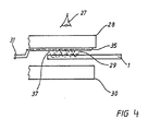
- FIG. 4 shows a modification of the exemplary embodiment Figure 1 that an electrode assembly 35 only on one single carrier 28 can be arranged, one Electrode arrangement is used, such as with of the electrode arrangement 35 according to FIG. 5.
- the upper carrier 28 in turn consists of a transparent Glass or plastic, with a planar electrode arrangement 35 is described, which is shown in more detail in Figure 5.
- This Electrode arrangement is made of interlocking fingers Electrode fingers formed 39.40, the electrode fingers 39.40 form the field gap 26 between them and from each other are isolated. The entire arrangement is on an insulation layer 41 from e.g. Si oxide applied, the electrode fingers 40 conductive with each other through a base conductor 38 are connected, while the electrode fingers 39 by a Base conductor 38a (see FIG. 11) is conductive to one another are connected.
- the base conductors 38, 38a preferably consist of a gold layer, while the electrode fingers 39.40 from the ITO paste described above or consist of a transparent gold layer.
- FIG. 6 shows a modification of the exemplary embodiment Figure 4 that additionally on the inside of the upper Carrier 28, a fluorescent layer 42 can be arranged, which is caused by the emission emitted by the El printed image Is brought on.
- a fluorescent layer 42 lights up either in the visible area or in the invisible area Area.
- a modified exemplary embodiment in comparison to FIG. 4 shows Figure 7, where it can be seen that the previous described electrode assembly 35 on a now attached below Carrier 28 is attached and that of the electrode assembly alternating spring generated the value and Enforce security product 1 from below, so that it from above through the transparent carrier 30 without further notice can be observed without it being necessary in to arrange an electrode arrangement itself in the line of sight.
- Figures 4, 6 and 7 show that this is from the electrode assembly 35 alternating field 37 each generated the security document 1 - at least in the area of the EI print image 29.
- FIG. 8 it is shown that the image printed by the El emitted emission 43 as the primary emission on the fluorescence layer 42, which in turn has a secondary emission 44 generated either in the visible range of one Observer 27 can be detected or - in the invisible Area - can be evaluated by a test device.
- the test device according to FIGS. 9 to 11 essentially consists again from the two opposite beams 28,30, in the space between them is an alternating electric field is formed, being on one side of these two carriers 28,30 a housing 49 is arranged, which on its Top carries a switch 50 and which corresponding Batteries 46 for power supply and an electronic PCB 47 houses on which the electronics 48th is constructed.
- a switch 50 that is generated alternating electric field, which the as Security feature 9.10 trained El-print image 29 at least partially interspersed and lights up.
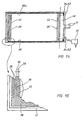
- FIG. 11 now shows that the previously described Electrode assembly 35 either on the inside of the lower one Carrier 30 or on the inside of the upper carrier 28 can be arranged.
- Figures 12 and 13 show that the electrode fingers 39.40 in are spaced from each other and between field gaps 26 which are approximately parallel to one another are formed.
- Luminescence layer 51 can be arranged. The function of this The luminescence layer has already been shown in FIG. 20 explained.
- Figures 14 and 15 show how the electrode arrangement 35 is integrated in the test device.
- the contacts 34 start and directly into the electronics 48 are introduced, to which a power supply unit 57 can be connected.
- the electrode arrangement 35 spaced from each other and isolating electrode fingers 39, 40 attached from one another, wherein Conductor widths 58 of typically 100 ⁇ m are preferred, at a conductor track spacing 59 of preferably 50 ⁇ m.
- An oxide layer is used for insulation over the entire arrangement applied by vapor deposition.
- Figure 16 shows that it is according to another embodiment is possible at the bottom of the security document 1 approximately flat electrode 32 in the form of a conductive printing ink 16 to bring up and contact them as well, then the value and security product 1 carries an El print image 29.
- the counter electrode is on a carrier of the test device arranged, which is described in the drawing Figure 17.
- the alternating field 36 generated between the two electrodes then passes through the El-active substances and brings them to light up.
- the height of the intaglio ink 2 above the base of security document 1 typically 10 to 20 ⁇ m
- the thickness 22 of the security document 1 typically 100 ⁇ m with a basis weight of 90g per square meter
- the thickness 23 of lower surface electrode 32 is about 3 to 10 microns.
- FIG. 17 shows the embodiment in FIG Figure 16 that the value and security product also on his Side - e.g. the bottom - with an electrode 32 can be coated, which contacts the one contact 34 becomes.
- the other contact is the surface contact of the Arranged on the inside of the upper, transparent support 28, wherein said electrode arrangement by a Insulation layer is covered, so that there as an electrode trained, full-surface ITO or gold coating if possible is completely covered by the insulation layer 41.
- the other contact 34 is conductive.
Landscapes
- Health & Medical Sciences (AREA)
- General Health & Medical Sciences (AREA)
- Toxicology (AREA)
- Physics & Mathematics (AREA)
- General Physics & Mathematics (AREA)
- Electroluminescent Light Sources (AREA)
- Illuminated Signs And Luminous Advertising (AREA)
- Credit Cards Or The Like (AREA)
Claims (9)
- Appareil de contrôle pour authentifier visuellement et/ou par machine des documents de valeur ou de sécurité qui présentent des signes distinctifs de sécurité pourvus de substances électroluminescentes, caractérisé en ce qu'il comporte deux supports parallèles (28, 30) entre lesquels le document à contrôler peut être introduit, l'un au moins de ces supports (28, 30) étant transparent, et en ce qu'il est prévu sur l'un au moins des supports (28, 30) un dispositif à électrode (35) apte à générer un champ électrique alternatif qui traverse le produit de valeur et de sécurité (1) au moins aux endroits où sont disposés les signes distinctifs de sécurité actifs par électroluminescence (9, 10, 29), lesquels sont ainsi excités de telle sorte qu'ils émettent des photons qui sont aptes à être évalués visuellement ou à l'aide d'une machine.
- Appareil de contrôle selon la revendication 1, caractérisé en ce que les deux électrodes sont disposées sous la forme d'un dispositif à électrode commun (35) sur un côté d'un support fixe (28 ou 30).
- Appareil de contrôle selon la revendication 1 ou 2, caractérisé en ce que le dispositif à électrode (35) est sensiblement plat, avec des électrodes (39, 40) qui sont disposées à peu près sur le même plan et côte à côte et qui définissent entre elles un interstice de champ (26), les signes distinctifs de sécurité actifs par électroluminescence étant traversés par les lignes de champ du champ électrique alternatif générées dans cet interstice (26).
- Appareil de contrôle selon la revendication 3, caractérisé en ce que le dispositif à électrode (35) se compose d'électrodes en forme de doigts (39, 40) qui s'interpénètrent et qui définissent entre elles un interstice de champ sinueux (26).
- Appareil de contrôle selon l'une des revendications 1 à 4, caractérisé en ce que le dispositif à électrode est appliqué sur une couche isolante (41).
- Appareil de contrôle pour authentifier visuellement et/ou par machine des documents de valeur ou de sécurité qui présentent des signes distinctifs de sécurité pourvus de substances électroluminescentes, caractérisé en ce qu'il comporte deux supports parallèles (28, 30) entre lesquels le document à contrôler peut être introduit, l'un au moins de ces supports (28, 30) étant transparent, et en ce qu'il est prévu sur les deux supports (28, 30) des électrodes (32, 33 ; 53, 54) qui génèrent entre elles, à la manière de condensateurs à lames, un champ électrique alternatif qui traverse le produit de valeur et de sécurité (1) au moins aux endroits où sont disposés les signes distinctifs de sécurité actifs par électroluminescence (9, 10, 29), lesquels sont ainsi excités de telle sorte qu'ils émettent des photons qui sont aptes à être évalués visuellement ou à l'aide d'une machine.
- Appareil de contrôle selon la revendication 6, caractérisé en ce que les deux électrodes (32, 33) sont disposées face à face sur les supports (28, 30) et en ce que le produit de valeur et de sécurité (1) est apte à être introduit dans une fente d'introduction (56) entre les électrodes (32, 33).
- Appareil de contrôle pour authentifier visuellement et/ou par machine des documents de valeur ou de sécurité qui présentent des signes distinctifs de sécurité pourvus de substances électroluminescentes, caractérisé en ce qu'il comporte deux supports parallèles (28, 30) entre lesquels le document à contrôler peut être introduit, l'un au moins de ces supports (28, 30) étant transparent, et en ce qu'il est prévu une première électrode (16, 32) sur le produit de valeur et de sécurité (1), et une seconde électrode (45) sur l'un des supports (28), qui génèrent entre elles un champ électrique alternatif qui traverse le produit de valeur et de sécurité (1) au moins aux endroits où sont disposés les signes distinctifs de sécurité actifs par électroluminescence (9, 10, 29), lesquels sont ainsi excités de telle sorte qu'ils émettent des photons qui sont aptes à être évalués visuellement ou à l'aide d'une machine.
- Appareil de contrôle selon l'une des revendications 1 à 8, caractérisé en ce qu'il est prévu, sur l'une des plaques de support (28 ou 30), une couche fluorescente (42) qui génère dans la zone visible un rayonnement secondaire à partir d'un rayonnement primaire visible ou invisible émis par le signe distinctif de sécurité actif par électroluminescence (29).
Applications Claiming Priority (3)
| Application Number | Priority Date | Filing Date | Title |
|---|---|---|---|
| DE19708543 | 1997-03-04 | ||
| DE19708543A DE19708543C2 (de) | 1997-03-04 | 1997-03-04 | Wert- und Sicherheitserzeugnis mit lumineszierenden Sicherheitselementen und Verfahren zur Herstellung derselben |
| EP98914854A EP0964791B1 (fr) | 1997-03-04 | 1998-02-25 | Produit de valeur et de securite avec elements de securite luminescents, procede de fabrication associe, et dispositif pour verifier visuellement et mecaniquement leur authenticite |
Related Parent Applications (1)
| Application Number | Title | Priority Date | Filing Date |
|---|---|---|---|
| EP98914854.9 Division | 1998-09-11 |
Publications (3)
| Publication Number | Publication Date |
|---|---|
| EP1059619A2 EP1059619A2 (fr) | 2000-12-13 |
| EP1059619A3 EP1059619A3 (fr) | 2000-12-20 |
| EP1059619B1 true EP1059619B1 (fr) | 2003-02-05 |
Family
ID=26034452
Family Applications (1)
| Application Number | Title | Priority Date | Filing Date |
|---|---|---|---|
| EP00119980A Expired - Lifetime EP1059619B1 (fr) | 1997-03-04 | 1998-02-25 | Dispositif pour la validation mécanique et visuelle de documents de valeur et de sécurité |
Country Status (1)
| Country | Link |
|---|---|
| EP (1) | EP1059619B1 (fr) |
Cited By (4)
| Publication number | Priority date | Publication date | Assignee | Title |
|---|---|---|---|---|
| WO2005116941A1 (fr) | 2004-05-07 | 2005-12-08 | Bundesdruckerei Gmbh | Dispositif d'authentification de papiers-valeurs ou de documents de securite |
| DE102013114496A1 (de) | 2013-12-19 | 2015-06-25 | Bundesdruckerei Gmbh | Zinksulfidischer Leuchtstoff mit Photo- und Elektrolumineszenzverhalten, Verfahren zu dessen Herstellung sowie Sicherheitsdokument, Sicherheitsmerkmal und Verfahren zu dessen Detektion |
| DE102020111461B3 (de) | 2020-04-27 | 2021-09-02 | Bundesdruckerei Gmbh | Sicherheitsmerkmal und Verfahren zu dessen Detektion sowie Sicherheits- oder Wertdokument |
| DE102021119436A1 (de) | 2021-07-27 | 2023-02-02 | Bundesdruckerei Gmbh | Sicherheitsmerkmal und Verfahren zu dessen Detektion sowie Sicherheits- oder Wertdokument |
Family Cites Families (3)
| Publication number | Priority date | Publication date | Assignee | Title |
|---|---|---|---|---|
| US4355300A (en) * | 1980-02-14 | 1982-10-19 | Coulter Systems Corporation | Indicia recognition apparatus |
| US5394969A (en) * | 1991-12-31 | 1995-03-07 | Authentication Technologies, Inc. | Capacitance-based verification device for a security thread embedded within currency paper |
| DE4405860B4 (de) * | 1994-02-23 | 2006-11-23 | WHD elektronische Prüftechnik GmbH | Messanordnung zur Auswertung eines Metallfadens |
-
1998
- 1998-02-25 EP EP00119980A patent/EP1059619B1/fr not_active Expired - Lifetime
Cited By (9)
| Publication number | Priority date | Publication date | Assignee | Title |
|---|---|---|---|---|
| WO2005116941A1 (fr) | 2004-05-07 | 2005-12-08 | Bundesdruckerei Gmbh | Dispositif d'authentification de papiers-valeurs ou de documents de securite |
| DE102013114496A1 (de) | 2013-12-19 | 2015-06-25 | Bundesdruckerei Gmbh | Zinksulfidischer Leuchtstoff mit Photo- und Elektrolumineszenzverhalten, Verfahren zu dessen Herstellung sowie Sicherheitsdokument, Sicherheitsmerkmal und Verfahren zu dessen Detektion |
| WO2015091237A1 (fr) | 2013-12-19 | 2015-06-25 | Bundesdruckerei Gmbh | Substance luminescente à sulfure de zinc présentant un comportement photo- et électroluminescent, procédé pour la production de ladite substance et document de sécurité, caractéristique de sécurité et procédé de détection de ladite caractéristique de sécurité |
| US9670406B2 (en) | 2013-12-19 | 2017-06-06 | Leuchtstoffwerk Breitungen Gmbh | Zinc sulphide phosphor having photo- and electroluminescent properties, process for producing same, and security document, security feature and method for detecting same |
| DE102020111461B3 (de) | 2020-04-27 | 2021-09-02 | Bundesdruckerei Gmbh | Sicherheitsmerkmal und Verfahren zu dessen Detektion sowie Sicherheits- oder Wertdokument |
| WO2021219568A1 (fr) | 2020-04-27 | 2021-11-04 | Bundesdruckerei Gmbh | Élément de sécurité et son procédé de détection, et document de sécurité ou de valeur |
| EP4350649A2 (fr) | 2020-04-27 | 2024-04-10 | Bundesdruckerei GmbH | Caractéristique de sécurité et son procédé de détection ainsi que document de sécurité ou de valeur |
| DE102021119436A1 (de) | 2021-07-27 | 2023-02-02 | Bundesdruckerei Gmbh | Sicherheitsmerkmal und Verfahren zu dessen Detektion sowie Sicherheits- oder Wertdokument |
| WO2023006142A1 (fr) | 2021-07-27 | 2023-02-02 | Bundesdruckerei Gmbh | Élément de sécurité et son procédé de détection, et document de sécurité ou de valeur |
Also Published As
| Publication number | Publication date |
|---|---|
| EP1059619A2 (fr) | 2000-12-13 |
| EP1059619A3 (fr) | 2000-12-20 |
Similar Documents
| Publication | Publication Date | Title |
|---|---|---|
| DE19758587C2 (de) | Anordnung zur visuellen und maschinellen Echtheitsprüfung von Wert- und Sicherheitsdokumenten | |
| DE19735293C2 (de) | Wert- und Sicherheitserzeugnis mit Lumineszenzelement | |
| DE4429637A1 (de) | Nummernschild mit Leuchtzeichen | |
| DE4126051A1 (de) | Sicherheitsdokument mit eingebettetem sicherheitselement | |
| EP1059619B1 (fr) | Dispositif pour la validation mécanique et visuelle de documents de valeur et de sécurité | |
| DE3937183A1 (de) | Verfahren zu stoerstrahlungsdaempfung an leiterplatten | |
| DE3802317A1 (de) | Lumineszierendes substrat | |
| EP1804557A1 (fr) | Module de sécurité électronique | |
| DE102022128057A1 (de) | Schaltungssubstrat und Tastatur mit einem derartigen Schaltungssubstrat | |
| DE3850638T2 (de) | Lötstellenprüfvorrichtung durch electronische Messung der Lötstellenfläche. | |
| EP2976755B1 (fr) | Dispositif et procédé de contrôle en temps réel d'un document de valeur ou de sécurité | |
| DE102019116331B4 (de) | Messvorrichtung und verfahren zum herstellen einer messvorrichtung | |
| EP1804559A2 (fr) | Module de sécurité électronique | |
| DE102009030775B4 (de) | Kapazitive Sensoranordnung | |
| DE102005061553B4 (de) | Chipmodul | |
| EP2435993B1 (fr) | Microsystème pour reconnaître des caractéristiques prédéfinies de papiers de valeur, de documents de sécurité ou d'autres produits | |
| DE1275583B (de) | Festkoerper-Flachbildschirm, der ein Dielektrikum aufweist, das in einem elektrischen Feld luminesziert, und Verfahren zu dessen Herstellung | |
| DE112017000681T5 (de) | Ozongenerierungs-Bauelement und Ozongenerierungsvorrichtung | |
| DE112017001230T5 (de) | Ozongenerierungs-Bauelement und Ozongenerierungsvorrichtung | |
| DE3802318A1 (de) | Lumineszierendes substrat | |
| WO2011042198A1 (fr) | Set d'identification et procédé d'identification d'une étiquette d'identification | |
| DE10065865A1 (de) | Vorrichtung zum Erzeugen eines Schaltsignals | |
| DE102016201861A1 (de) | Haushaltsgerät mit einer Bedienblende | |
| DE3937445A1 (de) | Elektrische schutzvorrichtung | |
| DE102022113433A1 (de) | Kontaktstecker und Set aus einer elektrischen Anschlussklemme und einem Kontaktstecker |
Legal Events
| Date | Code | Title | Description |
|---|---|---|---|
| PUAI | Public reference made under article 153(3) epc to a published international application that has entered the european phase |
Free format text: ORIGINAL CODE: 0009012 |
|
| PUAL | Search report despatched |
Free format text: ORIGINAL CODE: 0009013 |
|
| 17P | Request for examination filed |
Effective date: 20000914 |
|
| AC | Divisional application: reference to earlier application |
Ref document number: 964791 Country of ref document: EP |
|
| AK | Designated contracting states |
Kind code of ref document: A2 Designated state(s): AT BE CH DE DK ES FI FR GB GR IE IT LI LU MC NL PT SE |
|
| AK | Designated contracting states |
Kind code of ref document: A3 Designated state(s): AT BE CH DE DK ES FI FR GB GR IE IT LI LU MC NL PT SE |
|
| RIC1 | Information provided on ipc code assigned before grant |
Free format text: 7G 07D 7/00 A, 7B 41M 3/14 B |
|
| RIN1 | Information on inventor provided before grant (corrected) |
Inventor name: SCHMIDT, WOLFGANG Inventor name: AHLERS, BENEDIKT DR. Inventor name: FRANZ-BURGHOLZ, ARNIM Inventor name: GUTMANN, ROLAND DR. Inventor name: KAPPE, FRANK |
|
| AKX | Designation fees paid |
Free format text: AT BE CH DE DK ES FI FR GB GR IE IT LI LU MC NL PT SE |
|
| GRAH | Despatch of communication of intention to grant a patent |
Free format text: ORIGINAL CODE: EPIDOS IGRA |
|
| RIN1 | Information on inventor provided before grant (corrected) |
Inventor name: GUTMANN, ROLAND DR. Inventor name: SCHMIDT, WOLFGANG Inventor name: AHLERS, BENEDIKT DR. Inventor name: FRANZ-BURGHOLZ, ARNIM Inventor name: KAPPE, FRANK |
|
| GRAH | Despatch of communication of intention to grant a patent |
Free format text: ORIGINAL CODE: EPIDOS IGRA |
|
| GRAA | (expected) grant |
Free format text: ORIGINAL CODE: 0009210 |
|
| AC | Divisional application: reference to earlier application |
Ref document number: 0964791 Country of ref document: EP Kind code of ref document: P |
|
| AK | Designated contracting states |
Designated state(s): AT BE CH DE DK ES FI FR GB GR IE IT LI LU MC NL PT SE |
|
| REG | Reference to a national code |
Ref country code: GB Ref legal event code: FG4D Free format text: NOT ENGLISH |
|
| REG | Reference to a national code |
Ref country code: CH Ref legal event code: EP |
|
| PG25 | Lapsed in a contracting state [announced via postgrant information from national office to epo] |
Ref country code: MC Free format text: LAPSE BECAUSE OF NON-PAYMENT OF DUE FEES Effective date: 20030228 |
|
| REG | Reference to a national code |
Ref country code: IE Ref legal event code: FG4D Free format text: GERMAN |
|
| REF | Corresponds to: |
Ref document number: 59807143 Country of ref document: DE Date of ref document: 20030313 Kind code of ref document: P |
|
| REG | Reference to a national code |
Ref country code: CH Ref legal event code: NV Representative=s name: ABACUS PATENTANWAELTE KLOCKE SPAETH BARTH |
|
| REG | Reference to a national code |
Ref country code: SE Ref legal event code: TRGR |
|
| REG | Reference to a national code |
Ref country code: GR Ref legal event code: EP Ref document number: 20030401499 Country of ref document: GR |
|
| REG | Reference to a national code |
Ref country code: DK Ref legal event code: T3 |
|
| REG | Reference to a national code |
Ref country code: PT Ref legal event code: SC4A Free format text: AVAILABILITY OF NATIONAL TRANSLATION Effective date: 20030505 |
|
| GBT | Gb: translation of ep patent filed (gb section 77(6)(a)/1977) | ||
| ET | Fr: translation filed | ||
| REG | Reference to a national code |
Ref country code: ES Ref legal event code: FG2A Ref document number: 2192509 Country of ref document: ES Kind code of ref document: T3 |
|
| PLBE | No opposition filed within time limit |
Free format text: ORIGINAL CODE: 0009261 |
|
| STAA | Information on the status of an ep patent application or granted ep patent |
Free format text: STATUS: NO OPPOSITION FILED WITHIN TIME LIMIT |
|
| 26N | No opposition filed |
Effective date: 20031106 |
|
| REG | Reference to a national code |
Ref country code: FR Ref legal event code: PLFP Year of fee payment: 19 |
|
| REG | Reference to a national code |
Ref country code: FR Ref legal event code: PLFP Year of fee payment: 20 |
|
| PGFP | Annual fee paid to national office [announced via postgrant information from national office to epo] |
Ref country code: SE Payment date: 20170221 Year of fee payment: 20 Ref country code: DE Payment date: 20170222 Year of fee payment: 20 Ref country code: CH Payment date: 20170221 Year of fee payment: 20 Ref country code: GR Payment date: 20170217 Year of fee payment: 20 Ref country code: FI Payment date: 20170217 Year of fee payment: 20 Ref country code: FR Payment date: 20170220 Year of fee payment: 20 |
|
| PGFP | Annual fee paid to national office [announced via postgrant information from national office to epo] |
Ref country code: AT Payment date: 20170217 Year of fee payment: 20 Ref country code: GB Payment date: 20170221 Year of fee payment: 20 Ref country code: IE Payment date: 20170223 Year of fee payment: 20 Ref country code: NL Payment date: 20170220 Year of fee payment: 20 Ref country code: LU Payment date: 20170220 Year of fee payment: 20 Ref country code: DK Payment date: 20170222 Year of fee payment: 20 Ref country code: PT Payment date: 20170221 Year of fee payment: 20 Ref country code: BE Payment date: 20170220 Year of fee payment: 20 |
|
| PGFP | Annual fee paid to national office [announced via postgrant information from national office to epo] |
Ref country code: IT Payment date: 20170217 Year of fee payment: 20 Ref country code: ES Payment date: 20170220 Year of fee payment: 20 |
|
| REG | Reference to a national code |
Ref country code: DE Ref legal event code: R071 Ref document number: 59807143 Country of ref document: DE |
|
| REG | Reference to a national code |
Ref country code: DK Ref legal event code: EUP Effective date: 20180225 |
|
| REG | Reference to a national code |
Ref country code: NL Ref legal event code: MK Effective date: 20180224 Ref country code: CH Ref legal event code: PL |
|
| REG | Reference to a national code |
Ref country code: BE Ref legal event code: MK Effective date: 20180225 |
|
| REG | Reference to a national code |
Ref country code: GB Ref legal event code: PE20 Expiry date: 20180224 |
|
| REG | Reference to a national code |
Ref country code: IE Ref legal event code: MK9A |
|
| REG | Reference to a national code |
Ref country code: AT Ref legal event code: MK07 Ref document number: 232326 Country of ref document: AT Kind code of ref document: T Effective date: 20180225 |
|
| PG25 | Lapsed in a contracting state [announced via postgrant information from national office to epo] |
Ref country code: IE Free format text: LAPSE BECAUSE OF EXPIRATION OF PROTECTION Effective date: 20180225 Ref country code: GB Free format text: LAPSE BECAUSE OF EXPIRATION OF PROTECTION Effective date: 20180224 |
|
| PG25 | Lapsed in a contracting state [announced via postgrant information from national office to epo] |
Ref country code: PT Free format text: LAPSE BECAUSE OF EXPIRATION OF PROTECTION Effective date: 20180306 |
|
| REG | Reference to a national code |
Ref country code: ES Ref legal event code: FD2A Effective date: 20200904 |
|
| PG25 | Lapsed in a contracting state [announced via postgrant information from national office to epo] |
Ref country code: ES Free format text: LAPSE BECAUSE OF EXPIRATION OF PROTECTION Effective date: 20180226 |