EP1059654A2 - Thermischer Lastschalter - Google Patents
Thermischer Lastschalter Download PDFInfo
- Publication number
- EP1059654A2 EP1059654A2 EP00107772A EP00107772A EP1059654A2 EP 1059654 A2 EP1059654 A2 EP 1059654A2 EP 00107772 A EP00107772 A EP 00107772A EP 00107772 A EP00107772 A EP 00107772A EP 1059654 A2 EP1059654 A2 EP 1059654A2
- Authority
- EP
- European Patent Office
- Prior art keywords
- actuator
- contact
- trip
- switch
- metallic element
- Prior art date
- Legal status (The legal status is an assumption and is not a legal conclusion. Google has not performed a legal analysis and makes no representation as to the accuracy of the status listed.)
- Withdrawn
Links
- 229910052751 metal Inorganic materials 0.000 claims abstract description 73
- 239000002184 metal Substances 0.000 claims description 31
- 239000007787 solid Substances 0.000 claims description 29
- 230000004044 response Effects 0.000 claims description 9
- 230000007935 neutral effect Effects 0.000 claims description 4
- 230000000694 effects Effects 0.000 claims description 3
- 230000001747 exhibiting effect Effects 0.000 claims 1
- 238000012544 monitoring process Methods 0.000 claims 1
- 230000006835 compression Effects 0.000 abstract description 8
- 238000007906 compression Methods 0.000 abstract description 8
- 230000001012 protector Effects 0.000 description 7
- 230000009471 action Effects 0.000 description 5
- 238000002955 isolation Methods 0.000 description 5
- 230000005405 multipole Effects 0.000 description 5
- 238000004519 manufacturing process Methods 0.000 description 3
- 230000007246 mechanism Effects 0.000 description 3
- 230000001681 protective effect Effects 0.000 description 3
- 238000010586 diagram Methods 0.000 description 2
- 230000003213 activating effect Effects 0.000 description 1
- 230000004913 activation Effects 0.000 description 1
- 230000004888 barrier function Effects 0.000 description 1
- 230000008859 change Effects 0.000 description 1
- 238000010276 construction Methods 0.000 description 1
- 230000001351 cycling effect Effects 0.000 description 1
- 230000000881 depressing effect Effects 0.000 description 1
- 230000000994 depressogenic effect Effects 0.000 description 1
- 239000011810 insulating material Substances 0.000 description 1
- 239000007769 metal material Substances 0.000 description 1
- 238000003303 reheating Methods 0.000 description 1
Images







Classifications
-
- H—ELECTRICITY
- H01—ELECTRIC ELEMENTS
- H01H—ELECTRIC SWITCHES; RELAYS; SELECTORS; EMERGENCY PROTECTIVE DEVICES
- H01H73/00—Protective overload circuit-breaking switches in which excess current opens the contacts by automatic release of mechanical energy stored by previous operation of a hand reset mechanism
- H01H73/22—Protective overload circuit-breaking switches in which excess current opens the contacts by automatic release of mechanical energy stored by previous operation of a hand reset mechanism having electrothermal release and no other automatic release
- H01H73/26—Protective overload circuit-breaking switches in which excess current opens the contacts by automatic release of mechanical energy stored by previous operation of a hand reset mechanism having electrothermal release and no other automatic release reset by tumbler
-
- H—ELECTRICITY
- H01—ELECTRIC ELEMENTS
- H01H—ELECTRIC SWITCHES; RELAYS; SELECTORS; EMERGENCY PROTECTIVE DEVICES
- H01H71/00—Details of the protective switches or relays covered by groups H01H73/00 - H01H83/00
- H01H71/10—Operating or release mechanisms
- H01H71/12—Automatic release mechanisms with or without manual release
- H01H71/123—Automatic release mechanisms with or without manual release using a solid-state trip unit
-
- H—ELECTRICITY
- H01—ELECTRIC ELEMENTS
- H01H—ELECTRIC SWITCHES; RELAYS; SELECTORS; EMERGENCY PROTECTIVE DEVICES
- H01H71/00—Details of the protective switches or relays covered by groups H01H73/00 - H01H83/00
- H01H71/10—Operating or release mechanisms
- H01H71/12—Automatic release mechanisms with or without manual release
- H01H71/123—Automatic release mechanisms with or without manual release using a solid-state trip unit
- H01H2071/124—Automatic release mechanisms with or without manual release using a solid-state trip unit with a hybrid structure, the solid state trip device being combined with a thermal or a electromagnetic trip
-
- H—ELECTRICITY
- H01—ELECTRIC ELEMENTS
- H01H—ELECTRIC SWITCHES; RELAYS; SELECTORS; EMERGENCY PROTECTIVE DEVICES
- H01H83/00—Protective switches, e.g. circuit-breaking switches, or protective relays operated by abnormal electrical conditions otherwise than solely by excess current
- H01H83/20—Protective switches, e.g. circuit-breaking switches, or protective relays operated by abnormal electrical conditions otherwise than solely by excess current operated by excess current as well as by some other abnormal electrical condition
- H01H2083/206—Protective switches, e.g. circuit-breaking switches, or protective relays operated by abnormal electrical conditions otherwise than solely by excess current operated by excess current as well as by some other abnormal electrical condition with thermal shunt trip
-
- H—ELECTRICITY
- H01—ELECTRIC ELEMENTS
- H01H—ELECTRIC SWITCHES; RELAYS; SELECTORS; EMERGENCY PROTECTIVE DEVICES
- H01H71/00—Details of the protective switches or relays covered by groups H01H73/00 - H01H83/00
- H01H71/10—Operating or release mechanisms
- H01H71/50—Manual reset mechanisms which may be also used for manual release
- H01H71/52—Manual reset mechanisms which may be also used for manual release actuated by lever
- H01H71/527—Manual reset mechanisms which may be also used for manual release actuated by lever making use of a walking beam with one extremity latchable, the other extremity actuating or supporting the movable contact and an intermediate part co-operating with the actuator
-
- H—ELECTRICITY
- H01—ELECTRIC ELEMENTS
- H01H—ELECTRIC SWITCHES; RELAYS; SELECTORS; EMERGENCY PROTECTIVE DEVICES
- H01H83/00—Protective switches, e.g. circuit-breaking switches, or protective relays operated by abnormal electrical conditions otherwise than solely by excess current
- H01H83/20—Protective switches, e.g. circuit-breaking switches, or protective relays operated by abnormal electrical conditions otherwise than solely by excess current operated by excess current as well as by some other abnormal electrical condition
Definitions
- the present invention relates to thermal circuit protector devices which also function as ON/OFF switches, and deals more particularly with a structure that is simpler and less expensive to manufacture.
- the thermal circuit protector/switch structure also prevents a continuance or a cycling of an overload condition in the event manual override is attempted.
- Switches for use either as a thermal protector circuit breaker or switch are known. Snap action bi-metallic elements have been embodied in similar thermal protectors which employ a flag of insulating material to project between the switch contacts when the bi-metal element senses an overload condition. See U.S. Pat. Nos. 5,089,799 and 5,264,817 for examples of thermal protective switches of the type utilizing such a flag.
- thermostatic switches have a snap action disc that can be reset by a push button. See U.S. Patent Nos. 4,791,397 and 4,628,295 for examples of disc type devices.
- thermal circuit breakers are also known. See U.S. Patent Nos. 4,931,762; 4,937,548; and 4,258,349 for examples.
- thermal circuit breaker and switch uses the bi-metal element as the contact arm. See U.S. Patent No. 5,847,638.
- the general purpose of the present invention is to provide a thermal circuit breaker and switch that does not require a flag, and has both the appearance and functional capability of a conventional rocker switch, and wherein the device is also capable of "trip free" operation so that even if manually held in the 'on' or closed position, will not result in re-closing of the contacts and hence reheating of the bi-metal.
- the present invention avoids the stresses imposed on the bi-metal element when used as a contact arm although the bi-metal is provided in the circuit path. Individual contact and trip actuators are provided to avoid stressing the bi-metal, thus improving both accuracy and stability of operation. While slightly more complicated and expensive than the embodiment using the bi-metal as the contact arm, this invention remains less expensive to manufacture than other thermal circuit breaker designs which have the bi-metal separate from the contact.
- a molded hollow housing of either single body or split case construction is provided with a bottom wall and defines a top opening for pivotally receiving a rocker or bat type operator.
- the housing interior has a sidewall defining at least one vertical track to movably receive a contact actuator.
- An integrally molded socket pivotally receives and supports a trip actuator.
- the housing bottom wall is fitted with fixed line and load terminals.
- the rocker includes an extension or depending post that projects inside said housing and engages the contact actuator.
- a single compression spring biases the rocker toward the 'off' position and biases the trip actuator toward the normal position.
- One end of a movable conductive contact arm is fixedly mounted to a conductive jumper plate or directly connected to one end of the bi-metal, which is electrically connected to the load terminal.
- the opposite free end of the contact arm carries a movable contact element and is biased upwardly toward the contact actuator to normally urge said movable contact element away from a fixed contact element mounted to the line terminal.
- the contact actuator includes lateral projections that are slideable in said housing vertical track, such that movement of the rocker also moves the movable contact arm at least when said device is operated as a switch and there is no overload condition.
- the trip actuator is 'L' shaped and has upstanding and vertical legs that are fixedly joined at adjacent ends.
- the 'L' shaped trip actuator is pivotally supported at this juncture in a socket defined for it in the housing.
- the horizontal leg has projecting pins received in vertical channels in the housing and the upstanding vertical legs engage said contact actuator via interfacing surfaces on both the contact actuator and the trip actuator.
- a bi-metallic element moves into engagement with the horizontal leg of the trip actuator, pivoting the trip actuator and thereby disengaging the end of the contact actuator from the trip actuator. This allows the movable contact arm's inherent bias to open the contacts as a result of the overcurrent/overheat condition in the bi-metallic element.
- the bi-metallic element is 'U' shaped having the end of one arm of the U fixedly connected to the load terminal, and the end of the opposing arm fixedly connected to the contact arm, either directly or through a conductive jumper.
- the bi-metallic element electrically connects the line terminal to the movable contact arm and its movable contact.
- the bi-metallic element exhibits a thermally responsive change in shape or curvature such that the unrestrained free end base of the 'U' will bend upwardly toward the trip actuator in response to a predetermined current generating a temperature rise of the bi-metallic element.
- Biasing means in the form of a single compression spring is provided between the underside of the rocker and the upper end of the trip actuator's vertical legs.
- a single spring biases both the rocker to its 'off' position and the trip actuator to its normal position engaging the contact actuator in the absence of an overload condition.
- the rocker's lower extension cannot cause the contact actuator to move the movable contact arm into a contact closed condition since one end of the contact actuator is not constrained by engagement with the trip actuator.
- the spring bias forces said rocker toward the 'off' position.
- FIG. 1 shows a molded hollow housing 20 of the type having a generally rectangular upwardly open cavity for containing the following components.
- a pivotally mounted rocker 22 or other operator has laterally extending axle defining projections 22a received in axle openings 20a in the housing sidewalls 20b.
- the housing sidewalls 20b have molded vertical tracks 20c for slideably receiving track guide projections 24a on a contact actuator 24.
- the track also defines a stop surface 20h for a projecting pin 26e on a trip actuator 26.
- the housing sidewalls 20b also define sockets 20d to receive axle defining projections 26a on the trip actuator.
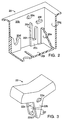
- the L-shaped trip actuator 26 is pivotally mounted in the housing 20.
- An integrally molded barrier 20e in the housing insulates a terminal element 34 that has a fixed contact 28 mounted on the end of said terminal element 34.
- the housing 20 also defines a housing stop projection 20f to abut a stop 24b on the contact actuator 24, and thereby limit said actuator's upward movement.
- the stop projection 20f provides a pivot point to cause the opposite end of the contact actuator to rise above the engaging surface of the trip actuator due to the pressure exerted against the contact actuator by the upward bias of the contact arm.
- a load and a line terminal extend through slots in the housing bottom wall 20i.
- the line terminal 32 incorporates a threaded opening 32a which accepts an adjustment or calibration screw 36.
- the load terminal 32 extends upwardly along the housing end wall opposite wall 20g and an upper end of terminal 32 connects with one end of a bi-metallic element 38.
- the element 38 is shown in Fig. 11 to have a "U" shape having a base and parallel arms 38a and 38b, and is oriented in a plane roughly parallel to the housing bottom wall 20i.
- the bi-metallic element 38 has a thermally responsive character such that a rise in temperature, as in an overcurrent condition, causes the bi-metallic element to curve towards the trip actuator 26.
- the end of the calibration screw 36 contacts the lower surface of the bi-metallic element 38 to define the normal configuration for the element 38, and hence the extent of the deformation thereof that is required to trip the trip actuator 26.
- the "U" shaped bi-metallic element has the end of one arm 38a connected to the fixed end of a movable contact arm 40.
- a conductive jumper 52 connects the one bi-metallic element arm to said movable contact arm.
- the bi-metallic element may be directly connected to the movable contact arm.
- the opposing arm 38b of the bi-metallic element is connected to an offset 32b of the line terminal 32 so that current flows through the bi-metallic element 38.
- the movable contact arm 40 is composed of a spring metal material and includes a contact element 30 at its free end which is biased upward and away from the fixed contact element 28.
- the fixed contact element 28 is mounted on the load terminal 34 and so positioned that when the movable contact arm 40 is forced downward by the contact actuator, the movable contact element 30 closes the circuit with contact 28.
- the second line terminal 34 is mounted abutting the housing end wall 20g that is opposite to the legs of the bi-metallic element's fixed ends.
- the rocker or operator 22 pivotally mounted in the housing axle openings 20a is biased by a spring 42 to the open-circuit or 'off' position.
- An integrally molded extension 22b or depending post is provided integrally in said rocker and is oriented roughly vertically when the rocker 22 is in the 'on' position. (See FIG. 8).
- the rocker extension's surface 22c movably engages the contact actuator's upper surface 24d.
- the rocker also has extensions below the contact actuator 24, with one or more inward facing projections 22d. These projections 22d engage part of the lower surface of the contact actuator 24 at 24g to assure the resetting of the end 24f above the trip actuator surface 26d when the thermal protector is in the 'off' position.
- the contact actuator 24 is provided between the upwardly biased movable contact arm 40 and the rocker 22.
- a contact stop 24b abuts the housing stop 20f at the housing sidewall to limit upward movement of the right end (as shown) and cause a pivoting motion to effect the upward movement of end 24f.
- the rocker's surface 22c provides a limit stop to the upward movement of the contact actuator on surface 24d. This upward movement is effected by the upward biasing pressure of the contact arm against surface 24h of the contact actuator.
- the rocker 22 is biased to the 'off' position by the spring 42 and is stopped in the appropriate 'off' position by the top surface of the housing's projections 20f abutting the rocker's bottom surfaces 22e.
- the detent in the top surface of the contact actuator at 24e latches the rocker's surface 22c with sufficient pressure provided by the upward bias of the contact arm 40 to overcome the rocker's minimal bias to the 'off' position as effected by spring 42.
- the rocker is thereby held in the 'on' position and stopped at the appropriate 'on' position by stops 20k molded into the housing 20 which will abut the rocker at surfaces 22f.
- the contact actuator 24 has a lower surface 24c at the left end (as shown), which serves to selectively engage the trip actuator surface 26d for a purpose to be described.
- the trip actuator 26 is of an "L" shape with horizontal and vertical legs (26b and 26c, respectively), and wherein the horizontal leg 26b is positioned between the movable contact arm 40 and the bi-metallic element 38.
- Axle defining projections 26a on the trip actuator pivotally support it in the molded socket 20d defined by the housing.
- the trip actuator's vertical legs 26c rise above a surface 26d which normally engages surface 24c of the contact actuator to prevent downward movement of that end of the contact actuator.
- the rocker extension 22c when rotated counterclockwise (as shown), acts upon the surface 24d of the contact actuator so that the contact actuator 24 will pivot at the point where it abuts the surface 26d of the trip actuator.
- This pivot action will move the right end (as shown) of the contact actuator 24 and thereby drive down surface 24h against the movable contact arm 40 to close the contact elements (28 and 30).
- the surface 26d of the trip actuator 26 moves out from under the surface 24c of the contact actuator and will no longer support that end of the contact actuator 24 when the trip actuator 26 has pivoted or 'tripped' (counterclockwise as shown in FIG. 9) due to the upward movement of an over-heated bi-metal 38.
- the trip actuator 26 is provided with pin projections 26e that will abut the lower shelves 20h of the tracks 20c to limit downward rotation of said trip actuator in the 'reset' direction (clockwise as shown in FIGs. 6,7, & 8).
- a compression spring 42 is provided between the top of the trip actuator's vertical legs 26c and the lower surface of the rocker 22, biasing said rocker toward the 'off' position (FIG. 6).
- the spring 42 is so oriented that the spring force vector always passes slightly inboard of the trip actuator's pivot axis (shown generally at 26f), thereby always biasing the trip actuator to the normal, or reset position.
- FIG 12 An alternative embodiment is shown in FIG 12, wherein the bi-metal 38 is completely separate from the switch circuit between terminals 12a and 12b, and has independent terminals 12c and 12d.
- the bi-metal may thereby be connected to a circuit to enable the switch circuit to be opened by applying an overload current to the bi-metal from a remote source.
- FIGs. 13 and 14 A second alternative embodiment is shown in FIGs. 13 and 14, wherein a solid state sensor 46 detects the reaching of a particular voltage limit in the circuit, or alternatively, the reaching of a designated pre-programmed time limit after the switch circuit has been closed. When said sensor's pre-programmed limits are reached, the sensor circuit 46 activates a solid state switch circuit 44 to shunt an appropriate amount of current passing through the bi-metal 38 to ground. This current being shunted through the bi-metal to ground will be adequate to cause the bi-metal to overheat, thereby resulting in the bi-metal's activating the trip actuator and opening the contacts 28 and 30 of the switch circuit.
- the bi-metal not only provides the normal current protection feature, but at the same time serves as the driving mechanism of the shunt circuit 44 to effect an opening of the switch contacts when directed by the sensor 46. While numerous conditions can be monitored, depending upon the programming of the solid state sensor, the bi-metal's shunt-to-ground placement of the solid state switch 44 is the significant feature, as this still allows the bi-metal to perform its normal function of overcurrent protection. Many alternative or combined conditions may be monitored by the sensor, such as time, ground faults, low or fluctuating voltage, etc.
- FIG. 15 A third alternative embodiment is shown in FIG. 15 wherein a solenoid 50 has its armature arranged to exert force against the trip actuator 26, causing the circuit to open.
- the solenoid 50 takes the place of the bi-metal in the version with the solid state sensor and is employed as an alternative means to actuate the trip actuator. This embodiment eliminates the need for the calibration screw 36 and its threaded opening 32a.
- Figure 16 shows a fourth alternative employing a solenoid 50 controlled by a remote trip circuit which would be connected to terminals 33 and 35.
- Figure 18 shows a fifth alternative employing the hi-metallic element with a solid state switch 44 but without a solid state sensor circuit.
- the solid state switch in this version may be controlled by a remote sensor circuit which would apply a signal to terminal 35 to activate the solid state switch 44, causing it to shunt a controlled current passing through the hi-metallic element to ground, or neutral, and thereby trip the mechanism, opening the mechanical switch.
- Figure 19 shows a sixth alternative employing a solenoid in place of the bi-metallic element with the solid state switch 44.
- the solid state switch would, as in Figure 18, be controlled by a remote sensor circuit which would apply a signal to terminal 35 to activate the solid state switch 44 causing it to apply current to the solenoid and thereby trip the mechanism, opening the mechanical switch.
- any of the above embodiments may also be incorporated into a double or multi pole thermal circuit breaker and switch whereby a single trip action by a bi-mettalic element or solenoid in any one or more of the poles causes all the embodied poles to open.
- a multi-pole function would include two or more thermal circuit breaker and switch circuits mounted side by side in one housing. Common tripping of the multi-poles would be effected by the use of either a single trip actuator serving multi-poles or by inter-connecting separate trip actuators at each pole by linking them with a connecting pin or rod.
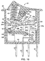
- FIG. 6 shows the rocker 22 in the spring biased 'off' position, the trip actuator 26 in the 'reset' position, and the left end of the contact actuator 24 abutting the trip stop 26d of said actuator.
- the upward bias of the movable contact arm 40 pushes the contact actuator 24 upwards until the actuator stop 24b abuts the housing stop 20f.
- Said housing stop 20f may alternatively be provided by an additional part or by an extension of the second terminal 34.
- the left end of the contact actuator 24 is held in position by the trip stop 26d and the rocker extension's lower surface 22c.
- the optionally employed inward facing projections 22d on the rocker extension 22b movably engage the lower surface 24g of the contact actuator 24.
- FIG. 7 shows the invention with the rocker 22 in transit towards the 'on' position with pressure applied to the left (as shown) portion of said rocker.
- Rotation of the rocker causes the lower surface 22c to travel across the contact actuator surface 24d, depressing the contact actuator in a downward clockwise direction as it pivots at the left end 24f (as shown) which is held in place by the trip stop 26d.
- the contact actuator 24 thereby transfers downward pressure at 24h to the contact arm 40 causing the contact arm 40 to move downward and close the contact elements 28 and 30.
- FIG. 8 shows the device in the closed circuit position with no overload condition.
- the rocker 22 is fully depressed to the 'on' position, wherein the rocker extension lower surface 22c rests in the 'on' position detent 24e of the contact actuator 24, and said contact actuator holds the movable contact arm 40 against its bias so that the contact elements (28 and 30) connect.
- the bias of the compression spring 42 is insufficient to overcome the resistance of the rocker extension lower surface 22c in the 'on' position detent 24e of the contact actuator 24.
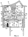
- FIG. 9 shows the device in the open-circuit position during an overload condition despite the rocker 22 being manually held to the 'on' position.
- the device is subjected to an electrical load greater than its rating, causing the bi-metallic element 38 to heat up and curve upwards and engages the trip actuator's horizontal leg 26b.
- Such engagement and the bias of the element 38 itself overcomes the compression spring's 42 bias and causes the trip actuator to pivot around its axle projections 26a that rest in the molded housing socket 20d. Consequently, the trip actuator's vertical legs 26c rotate outboard (counter-clockwise as shown in FIG. 9) toward the housing end wall opposite of wall 20g.
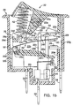
- FIG. 10 shows the invention with the rocker 22 in transit after an overload condition.
- the compression spring 42 drives the rocker to the 'off' position, after the rocker surface 22c is set free from engagement by the contact actuator detent 24e, due to the contact actuator 24 having rotated counter-clockwise (as shown) when the trip actuator surface 26d moves out from under surface 24c.
- the contact actuator 24 then pivots on stops 24b abutting the housing projections 20f, causing the opposite end 24f (left as shown) of the contact actuator to rise about surface 26d of the trip actuator.
- the trip actuator 26 rotates (clockwise as shown) back to the position shown in FIG. 2 due to the compression spring 42 bias and surface 26d moves underneath surface 24c of the contact actuator.
- the device is then reset back to the position shown in FIG 6.
- Figure 17 shows in block diagram form a circuit incorporating any of the devices (A) previously disclosed.
- the control circuitry (B) senses conditions comprising overvoltage, ground fault, temperature, undervoltage, time, or any combination thereof.
- a gate controlled switch (C) operates in response to the output from the control circuit (B). As shown, the thermal circuit protector and switch accompanying sensors are in the 'off', inactive position.
- a multi-pole version of the Figure 1 device is suggested in that view, wherein another similar device is provided alongside that shown so that a connecting rod or its equivalent can be provided at the pivot axis for the trip actuator to extend through an opening in the housing side wall(s) for connection to the trip actuator 27 in an adjacent device or pole.
Landscapes
- Breakers (AREA)
- Thermally Actuated Switches (AREA)
- Tumbler Switches (AREA)
Applications Claiming Priority (2)
| Application Number | Priority Date | Filing Date | Title |
|---|---|---|---|
| US328107 | 1999-06-08 | ||
| US09/328,107 US6094126A (en) | 1999-06-08 | 1999-06-08 | Thermal circuit breaker switch |
Publications (2)
| Publication Number | Publication Date |
|---|---|
| EP1059654A2 true EP1059654A2 (de) | 2000-12-13 |
| EP1059654A3 EP1059654A3 (de) | 2002-01-23 |
Family
ID=23279550
Family Applications (1)
| Application Number | Title | Priority Date | Filing Date |
|---|---|---|---|
| EP00107772A Withdrawn EP1059654A3 (de) | 1999-06-08 | 2000-04-11 | Thermischer Lastschalter |
Country Status (6)
| Country | Link |
|---|---|
| US (2) | US6094126A (de) |
| EP (1) | EP1059654A3 (de) |
| JP (1) | JP2001006513A (de) |
| CN (1) | CN1276616A (de) |
| NO (1) | NO20002822L (de) |
| TW (1) | TW473756B (de) |
Cited By (1)
| Publication number | Priority date | Publication date | Assignee | Title |
|---|---|---|---|---|
| TWI692792B (zh) * | 2019-01-15 | 2020-05-01 | 易湘雲 | 開關或用電設備的過熱斷電方法 |
Families Citing this family (36)
| Publication number | Priority date | Publication date | Assignee | Title |
|---|---|---|---|---|
| TW453504U (en) * | 1999-06-24 | 2001-09-01 | You Tsung Mou | Button switch having overload protection function |
| US6249209B1 (en) * | 1999-09-17 | 2001-06-19 | Tsung-Mou Yu | Switch structure having a current overloading protection mechanism |
| TW456574U (en) * | 1999-10-29 | 2001-09-21 | You Tsung Mou | Overload protection push button switch with indirectly driven auto-reset activated mechanism |
| US6252489B1 (en) * | 1999-11-10 | 2001-06-26 | Tsung-Mou Yu | Switch structure |
| US6275133B1 (en) * | 1999-12-03 | 2001-08-14 | Tsung-Mou Yu | Switch structure |
| US6307459B1 (en) * | 2000-01-05 | 2001-10-23 | Tsung-Mou Yu | Power switch device |
| US6353380B1 (en) * | 2000-01-27 | 2002-03-05 | Tsung-Mou Yu | Power switch device |
| US6307460B1 (en) * | 2000-02-01 | 2001-10-23 | Tsung-Mou Yu | Power switch device |
| US6275134B1 (en) * | 2000-03-01 | 2001-08-14 | Tsan-Chi Chen | Safety switch with a rocker type actuator and trip-off contact |
| US6552643B2 (en) * | 2000-12-11 | 2003-04-22 | Shang-Hao Chen | Structure of a depress-type safety switch |
| JP4011292B2 (ja) | 2001-01-15 | 2007-11-21 | 株式会社日立製作所 | 発光素子、及び表示装置 |
| US6483416B2 (en) * | 2001-02-22 | 2002-11-19 | Tsung-Mou Yu | Overload protection device of a press type switch |
| US6928093B2 (en) * | 2002-05-07 | 2005-08-09 | Cymer, Inc. | Long delay and high TIS pulse stretcher |
| US6525639B1 (en) * | 2001-08-15 | 2003-02-25 | Tsang-I Cheng | Power source electrical switch |
| US6608752B2 (en) | 2001-09-24 | 2003-08-19 | General Electric Company | Adaptive heat sink for electronics applications |
| US6577221B1 (en) * | 2001-11-30 | 2003-06-10 | Ming-Shan Wang | Safety switch |
| GB2387480B (en) * | 2002-04-09 | 2005-04-13 | Microsaic Systems Ltd | Micro-engineered self-releasing switch |
| US6713704B1 (en) * | 2003-02-03 | 2004-03-30 | Tsung-Mou Yu | Pushbutton assembly |
| US7026906B2 (en) * | 2003-12-19 | 2006-04-11 | Albert Huang | Circuit breaker |
| US7479868B2 (en) * | 2005-06-08 | 2009-01-20 | Therm-O-Disc, Incorporated | Trip-free manual reset thermostat |
| TWM322054U (en) * | 2007-05-18 | 2007-11-11 | Tzan-Chi Chen | Over-current protecting switch |
| US7583174B2 (en) * | 2007-11-14 | 2009-09-01 | Tsung Mou Yu | Safety switch |
| US7583175B2 (en) * | 2007-11-16 | 2009-09-01 | Tsung Mou Yu | Safety switch |
| US7626482B2 (en) * | 2008-01-22 | 2009-12-01 | Albert Huang | Safety switch |
| US7755465B2 (en) * | 2008-04-23 | 2010-07-13 | Sun-Lite Sockets Industry Inc. | Temperature control switch |
| US8310494B2 (en) * | 2008-09-30 | 2012-11-13 | Apple Inc. | Method for reducing graphics rendering failures |
| US7982577B2 (en) * | 2009-06-03 | 2011-07-19 | Tsung Mou Yu | Safety device for switch |
| US8154375B2 (en) * | 2009-10-07 | 2012-04-10 | Tsan-Chi Chen | Overcurrent protection device having trip free mechanism |
| KR101721105B1 (ko) * | 2011-06-24 | 2017-03-30 | 엘에스산전 주식회사 | 회로차단기의 간격 조정방법 |
| SG11201606674QA (en) | 2014-02-13 | 2016-09-29 | Ellenberger & Poensgen | Thermal overcurrent circuit breaker |
| CN103903910A (zh) * | 2014-04-16 | 2014-07-02 | 苏州华旃航天电器有限公司 | 汽车空调压缩机的热保护器 |
| WO2018115151A1 (en) * | 2016-12-23 | 2018-06-28 | Eaton Industries (Austria) Gmbh | Circuit breaker with manually closing and opening functionality and tripping functionality |
| TWI677146B (zh) * | 2018-07-03 | 2019-11-11 | 易湘雲 | 熱破壞斷電的開關及具有該開關的插座 |
| CN114783843B (zh) * | 2021-01-22 | 2025-02-07 | 王怡翔 | 具反向重启切换结构的完全跳脱过载保护开关 |
| CN114695031A (zh) * | 2022-03-25 | 2022-07-01 | 江苏紫米电子技术有限公司 | 微型断路器、电路开关及电路开关的过载保护方法 |
| CN116741597B (zh) * | 2023-06-16 | 2024-01-09 | 国网黑龙江省电力有限公司营销服务中心 | 一种家居电力负荷监测装置 |
Family Cites Families (29)
| Publication number | Priority date | Publication date | Assignee | Title |
|---|---|---|---|---|
| DE2721162C2 (de) * | 1977-05-11 | 1982-04-08 | Ellenberger & Poensgen Gmbh, 8503 Altdorf | Überstromschutzschalter mit Ein- und Ausschaltwippe |
| CH647094A5 (en) * | 1979-11-09 | 1984-12-28 | Weber Ag Fab Elektro | Two-pole protective circuit breaker with thermal tripping |
| US4337450A (en) * | 1980-06-09 | 1982-06-29 | Eaton Corporation | Remote control electro-thermal actuator switch |
| US4345233A (en) * | 1981-03-02 | 1982-08-17 | Eaton Corporation | Manual switch with timed electro-thermal latch release |
| US4363016A (en) * | 1981-06-03 | 1982-12-07 | Amf Incorporated | Circuit breaker |
| FR2516305A1 (fr) * | 1981-11-06 | 1983-05-13 | Merlin Gerin | Disjoncteur de branchement a controle de la puissance souscrite par un module pilote |
| US4559510A (en) * | 1982-10-11 | 1985-12-17 | Heinrich Kopp Gmbh & Co. Kg. | Equipment protecting electrical circuit breaker |
| IT8322533V0 (it) * | 1983-07-28 | 1983-07-28 | Bassani Spa | Interruttore automatico unipolare di piccole dimensioni. |
| US4528538A (en) * | 1984-01-13 | 1985-07-09 | Andersen James H | Combined switch and circuit breaker |
| US4628295A (en) * | 1984-05-04 | 1986-12-09 | Aisin Seiki Kabushiki Kaisha | Temperature responsive switch |
| JPS63269431A (ja) * | 1987-04-24 | 1988-11-07 | Matsushita Electric Works Ltd | 過電流遮断器 |
| US4791397A (en) * | 1987-06-30 | 1988-12-13 | Therm-O-Disc, Incorporated | Thermostatic switch construction |
| US4931762A (en) * | 1989-04-13 | 1990-06-05 | Heinemann Electric Company | Circuit breaker construction |
| JPH0722029Y2 (ja) * | 1989-10-09 | 1995-05-17 | ホシデン株式会社 | 自照式電源スイッチ付回路遮断器 |
| US4937548A (en) * | 1989-10-25 | 1990-06-26 | Mechanical Products, Inc. | Circuit breaker |
| US5012495A (en) * | 1990-03-19 | 1991-04-30 | Eagle Electric Mfg. Co. Inc. | Switch and circuit breaker combination device |
| US5089799A (en) * | 1991-01-25 | 1992-02-18 | Sorenson Richard W | Thermal switch/breaker |
| EP0513423B1 (de) * | 1991-05-17 | 1996-01-10 | Siemens Aktiengesellschaft | Leitungsschutzschalter mit Fernauslösung |
| US5262748A (en) * | 1992-01-13 | 1993-11-16 | Tsung Mou Yu | Fuseless breaking switch |
| US5264817A (en) * | 1993-02-11 | 1993-11-23 | Sorenson Richard W | Thermal circuit protective device |
| ATE151566T1 (de) * | 1993-03-17 | 1997-04-15 | Ellenberger & Poensgen | Geräteschalter mit integriertem überstromschutz |
| EP0616347B1 (de) * | 1993-03-17 | 1998-03-11 | Ellenberger & Poensgen GmbH | Mehrpoliger Schutzschalter |
| US5453725A (en) * | 1994-05-25 | 1995-09-26 | You; Long-Cheng | Overcurrent breaker switch |
| US5847638A (en) * | 1996-06-11 | 1998-12-08 | Sorenson; Richard W. | Thermal circuit protector and switch |
| US5889457A (en) * | 1997-04-28 | 1999-03-30 | Hsu; Cheng-Chao | Overload protective circuit breaker switch |
| US5786742A (en) * | 1997-07-14 | 1998-07-28 | Yin; Tien-Ning | Push button switch with override interruption structure |
| US5828284A (en) * | 1997-12-04 | 1998-10-27 | Huang; Albert | Circuit overload protective device |
| US5898355A (en) * | 1998-01-20 | 1999-04-27 | Yu; Tsung-Mou | Switch breaker having an arc prevention mechanism |
| US5892426A (en) * | 1998-06-12 | 1999-04-06 | Huang; Tse-Chuan | Safety switch with security structure |
-
1999
- 1999-06-08 US US09/328,107 patent/US6094126A/en not_active Expired - Fee Related
- 1999-09-02 US US09/388,771 patent/US6154116A/en not_active Expired - Fee Related
-
2000
- 2000-02-18 CN CN00102248.2A patent/CN1276616A/zh active Pending
- 2000-03-15 TW TW089104757A patent/TW473756B/zh not_active IP Right Cessation
- 2000-04-11 EP EP00107772A patent/EP1059654A3/de not_active Withdrawn
- 2000-06-02 NO NO20002822A patent/NO20002822L/no not_active Application Discontinuation
- 2000-06-08 JP JP2000172220A patent/JP2001006513A/ja active Pending
Cited By (1)
| Publication number | Priority date | Publication date | Assignee | Title |
|---|---|---|---|---|
| TWI692792B (zh) * | 2019-01-15 | 2020-05-01 | 易湘雲 | 開關或用電設備的過熱斷電方法 |
Also Published As
| Publication number | Publication date |
|---|---|
| NO20002822L (no) | 2000-12-11 |
| JP2001006513A (ja) | 2001-01-12 |
| CN1276616A (zh) | 2000-12-13 |
| TW473756B (en) | 2002-01-21 |
| US6094126A (en) | 2000-07-25 |
| NO20002822D0 (no) | 2000-06-02 |
| US6154116A (en) | 2000-11-28 |
| EP1059654A3 (de) | 2002-01-23 |
Similar Documents
| Publication | Publication Date | Title |
|---|---|---|
| US6094126A (en) | Thermal circuit breaker switch | |
| CA2105917C (en) | Attachment actuator arrangement for 1 and 2-pole ground fault | |
| US5089799A (en) | Thermal switch/breaker | |
| EP2242080B1 (de) | Testanordnung für einen Schutzschalter | |
| EP1059653A2 (de) | Thermischer Lastschalter | |
| US3426301A (en) | Interconnected multipole circuit breaker | |
| US5982269A (en) | Electric switch and thermal protector | |
| US4510479A (en) | PC-board mounted thermal breaker | |
| US4517543A (en) | SME overcurrent protective apparatus having ambient temperature compensation | |
| US7064636B1 (en) | Shape memory alloy trip mechanism for arc/ground fault circuit interruption | |
| CA1331470C (en) | Interrupter actuator | |
| US2913542A (en) | Two pole circuit breaker | |
| US6498310B1 (en) | Reverse alarm switch circuit breaker | |
| US3265831A (en) | Thermally responsive electrical control device | |
| US20040150497A1 (en) | Non-conductive barrier for separating a circuit breaker trip spring and cradle | |
| US4048607A (en) | Circuit breaker | |
| US3240904A (en) | Circuit breaker assembly | |
| US3723929A (en) | Bimetallic circuit overload protector | |
| US4375628A (en) | Circuit breaker | |
| US3990028A (en) | Multiple circuit thermal circuit breakers | |
| US4069464A (en) | Bimetal overload relay | |
| TW473757B (en) | Thermal circuit breaker switch | |
| US4083027A (en) | Pushbutton electric switch | |
| GB2090472A (en) | Circuit breaker with variable rate spring | |
| CA1092630A (en) | Bimetal overload relay |
Legal Events
| Date | Code | Title | Description |
|---|---|---|---|
| PUAI | Public reference made under article 153(3) epc to a published international application that has entered the european phase |
Free format text: ORIGINAL CODE: 0009012 |
|
| 17P | Request for examination filed |
Effective date: 20000411 |
|
| AK | Designated contracting states |
Kind code of ref document: A2 Designated state(s): AT BE CH CY DE DK ES FI FR GB GR IE IT LI LU MC NL PT SE |
|
| AX | Request for extension of the european patent |
Free format text: AL;LT;LV;MK;RO;SI |
|
| PUAL | Search report despatched |
Free format text: ORIGINAL CODE: 0009013 |
|
| AK | Designated contracting states |
Kind code of ref document: A3 Designated state(s): AT BE CH CY DE DK ES FI FR GB GR IE IT LI LU MC NL PT SE |
|
| AX | Request for extension of the european patent |
Free format text: AL;LT;LV;MK;RO;SI |
|
| AKX | Designation fees paid |
Free format text: AT BE CH CY DE DK ES FI FR GB GR IE IT LI LU MC NL PT SE |
|
| STAA | Information on the status of an ep patent application or granted ep patent |
Free format text: STATUS: THE APPLICATION IS DEEMED TO BE WITHDRAWN |
|
| 18D | Application deemed to be withdrawn |
Effective date: 20041103 |