EP1059697A2 - Connecteur étanche - Google Patents
Connecteur étanche Download PDFInfo
- Publication number
- EP1059697A2 EP1059697A2 EP00304552A EP00304552A EP1059697A2 EP 1059697 A2 EP1059697 A2 EP 1059697A2 EP 00304552 A EP00304552 A EP 00304552A EP 00304552 A EP00304552 A EP 00304552A EP 1059697 A2 EP1059697 A2 EP 1059697A2
- Authority
- EP
- European Patent Office
- Prior art keywords
- wall portion
- rubber plug
- housing
- connector
- recess
- Prior art date
- Legal status (The legal status is an assumption and is not a legal conclusion. Google has not performed a legal analysis and makes no representation as to the accuracy of the status listed.)
- Withdrawn
Links
- 238000007789 sealing Methods 0.000 claims abstract description 5
- 125000006850 spacer group Chemical group 0.000 description 27
- XLYOFNOQVPJJNP-UHFFFAOYSA-N water Substances O XLYOFNOQVPJJNP-UHFFFAOYSA-N 0.000 description 18
- 230000002093 peripheral effect Effects 0.000 description 16
- 210000000078 claw Anatomy 0.000 description 10
- 238000012856 packing Methods 0.000 description 9
- 229920003002 synthetic resin Polymers 0.000 description 5
- 239000000057 synthetic resin Substances 0.000 description 5
- 230000008014 freezing Effects 0.000 description 4
- 238000007710 freezing Methods 0.000 description 4
- 238000003780 insertion Methods 0.000 description 4
- 230000037431 insertion Effects 0.000 description 4
- 230000013011 mating Effects 0.000 description 2
- 238000004078 waterproofing Methods 0.000 description 2
- 230000000694 effects Effects 0.000 description 1
- 238000004519 manufacturing process Methods 0.000 description 1
- 238000005192 partition Methods 0.000 description 1
Images






Classifications
-
- H—ELECTRICITY
- H01—ELECTRIC ELEMENTS
- H01R—ELECTRICALLY-CONDUCTIVE CONNECTIONS; STRUCTURAL ASSOCIATIONS OF A PLURALITY OF MUTUALLY-INSULATED ELECTRICAL CONNECTING ELEMENTS; COUPLING DEVICES; CURRENT COLLECTORS
- H01R13/00—Details of coupling devices of the kinds covered by groups H01R12/70 or H01R24/00 - H01R33/00
- H01R13/46—Bases; Cases
- H01R13/52—Dustproof, splashproof, drip-proof, waterproof, or flameproof cases
- H01R13/5205—Sealing means between cable and housing, e.g. grommet
Definitions
- the present invention relates to a small-size multi-way waterproof connector in which waterproofing property between a connector housing and a plurality of electric wires connected with terminals is improved.
- a connector housing 11 of the waterproof connector 10'' consists of an inner housing 12 formed of a synthetic resin and including a plurality of terminal chambers 13 integrally formed therewith, an outer housing 17 formed of a synthetic resin into which the inner housing 12 is adapted to be inserted, and a spacer 28 interposed between the inner housing 12 and the outer housing 13 in order to hold female terminals 14 contained in the above described terminal chambers 13 respectively.
- the inner housing 12 has a box-like portion 12a of which an upper and a lower faces are open at their rearward ends.
- the above described terminal chambers 13 are formed in a space defined by a central horizontal wall 12b and vertical side walls 12c which also serve as partition walls.
- the female terminals 14 are adapted to be contained in the terminal chambers 13 respectively.
- the box-like portion 12a is integrally formed with projecting engagement claws 15 at opposite sides and a center of its upper and lower faces.
- Flange portions 16 are integrally formed so as to project from both sides of the box-like portion 12a at a center of its front face.
- each of the female terminals 14 has a pair of press-connection blades 14b which are bent from plate portions at both sides in the rear of a box-like portion 14a.
- the outer housing 17 is in a form of double boxes which are open at the front face, consisting of an inner wall portion 17a in a shape of substantially rectangular column, an outer wall portion 17b in a shape of substantially rectangular column enclosing the inner wall portion 17a, and a bottom wall portion (one wall portion) 17c connecting the inner and the outer wall portions 17a, 17b at their rear parts.
- a central part of the bottom wall portion 17c is formed as a thick wall portion.
- rubber plug chambers 19 each having a larger diameter and a circular cross section and in which waterproof rubber plugs 18 are contained by press-fitting or the like, at positions facing with the terminal chambers 13.
- each of the waterproof rubber plugs 18 is substantially in a form of a cylinder having undulations at both inner and outer peripheral faces, so that the electric wire 20 is adapted to pass therethrough without clearance.
- At the front center of the upper and lower walls of the inner wall portion 17a is provided rectangular longer locking slits 23 for engaging and disengaging with the engagement claws 15 formed at the center of the upper and lower faces of the box-like portion 12a of the inner housing 12.
- a V-shaped packing receiving portion 25 in a depth of the outer face of the inner wall portion 17a of the outer housing 17, is integrally formed a V-shaped packing receiving portion 25 in a projecting manner which is adapted to receive an annular waterproof packing 24 formed of rubber.
- Tapered faces 26 are respectively provided at front edges of the inner faces of the inner wall portion 17a at positions facing with the locking slits 22 and 23. Further, the upper and lower walls of the outer wall portion 17b of the outer housing 17 are respectively provided in their forward parts with locking holes 27 for engaging and disengaging with flexible locking arms of the mating connector (not shown).
- the spacer 28 is in a form of a box which opens at the front face, consisting of a body portion 28a in a shape of substantially rectangular column adapted to be fitted to the inner face of the inner wall portion 17a of the outer housing 17, a flange portion 28b in a shape of substantially rectangular column which is integrally formed with the body portion 28a so as to be bent backwardly from the front end thereof and adapted to be fitted to the outer face of the inner wall portion 17a of the outer housing 17, and a bottom wall portion 28c of the body portion 28a.
- the box-like portion 12a of the inner housing 12 is adapted to be inserted into the body portion 28a of the spacer 28.
- notches 30, 31 respectively at positions corresponding to the engagement claws 15 and the flange portions 16 of the inner housing 12.
- engagement claws 32 At outer faces of the upper and lower walls of the body portion 28a of the spacer 28 between the vertically arranged notches 30 are integrally formed engagement claws 32 for engaging and disengaging with the locking slits 23 in the outer housing 17.
- a distal end of the flange portion 28b of the spacer 28 is in such a form that it holds the packing 24 engaged in the packing receiving portion 25 in the inner wall portion 17a of the outer housing 17 when the spacer has been inserted in the outer housing 17.
- the bottom wall portion 28c of the spacer 28 is formed with electric wire through holes 33 at positions corresponding to the respective electric wire through holes 21 in the outer housing 17.
- the bottom wall portion 28c of the spacer 28 serves to hold the rubber plugs 18 which are inserted into the respective rubber plug chambers 19 in the bottom wall portion 17c of the outer housing 17, when the spacer has been fitted into the outer housing 17.
- the electric wires 20 passed through the electric wire through hole 21 in the outer housing 17, the rubber plugs 18, and the electric wire through holes 33 in the spacer 28 are press-connected between a pair of the press-connection blades 14b of the female terminals 14 contained in the terminal chambers 13 in the inner housing 12.
- the terminal chambers 13 and the electric wires 20 are sealed with the rubber plugs 18 and the packing 24 respectively.
- the rubber plugs 18 are first inserted in a fitting direction of the connector housing into the respective rubber plug chambers 19 inside the bottom wall portion 17c of the outer housing 17 which constitutes the exterior of the connector housing 11, and set as shown in Fig.9A. Then, the packing 24 is inserted and set in the packing receiving portion 25 in the inner wall 17a of the outer housing 17.
- the body portion 28a of the spacer 28 is inserted into the inner wall portion 17a of the outer housing 17 as shown in Fig. 9B, and the engagement claws 32 in the body portion 28a of the spacer 28 are locked in the respective locking slits 23 formed in the inner wall portion 17a of the outer housing 17.
- This locking action of the engagement claws 32 of the body portion 28a of the spacer 28 with the respective locking slits 23 in the inner wall portion 17a of the outer housing 17 will prevent withdrawal of the rubber plugs 18 in cooperation with the bottom wall portion 17c of the outer housing 17, and at the same time, withdrawal of the packing 24 in cooperation with the slanted distal end of the flange portion 28b of the spacer 28.
- the waterproofing property of the whole connector housing can be remarkably enhanced.
- the electric wires 20 are inserted from the electric wire through holes 21 in the bottom wall portion 17c of the outer housing 17 to pass through the rubber plugs 18 and the electric wire through holes 33 in the bottom wall portion 28c of the spacer 28 from the exterior.
- the electric wires 20 are press-connected to a pair of the press-connection blades 14b of the female terminals 14 contained in the terminal chambers 13 in the inner housing 12 which constitutes the interior of the connector housing 11.
- the inner housing 12 is inserted into the body portion 28a of the spacer 28, and the engagement claws 15 of the box-like portion 12a of the inner housing 12 are locked in the locking slits 23 in the inner wall portion 17a of the outer housing 17, thereby completing the assembly of the waterproof connector 10''.
- the rear end edge of the box-like portion 12a of the inner housing 12 and the rear end edges of the box-like portions 14a of the female terminals 14 are respectively locked by the projections 29 which project from the inner faces of the upper and lower walls of the body portion 28a of the spacer 28, and the projections 29 will not be deformed outwardly, the female terminals 14 can be surely prevented from withdrawing from the respective terminal chambers 13.
- the spacer 28 can be double locked by both the engagement of its own engagement claws 32 with the locking slits 23 in the outer housing 17 and the engagement of the engagement claws 15 in the inner housing 12 with the locking slits 23 in the outer housing 17. Therefore, the withdrawal of the rubber plugs 18 and the packing 24 can be surely prevented, and reliability in the waterproofness can be remarkably improved.
- the rubber plugs 18 are covered with the bottom wall portion 17c of the outer housing 17 and the peripheral wall portion 17d around the rubber plug chambers 19 in a completely enclosed state, and therefore, it has been difficult to confirm from the exterior whether or not the rubber plugs 18 are provided in the rubber plug chambers 19 (lack of components) in assembling the waterproof connector 10''.
- water intruded from the electric wire insertion inlets outside the electric wire through holes 21 in the outer housing 17 has been liable to stay in spaces S respectively formed between the rubber plug chambers 19 in the outer housing 17 and one ends 18a of the rubber plugs 18.
- the invention has been made to solve the above described problems, and it is an object of the invention to provide a multi-way connector in which the presence of the rubber plugs can be easily confirmed to improve assembling grade, and water which has intruded into the rubber plug chambers from the electric wire insertion inlets outside the electric wire through holes in the connector housing can be easily drained, thereby to reliably prevent the peripheral wall portion, etc. from being broken due to freezing of the water.
- a waterproof connector comprising:
- the presence of the rubber plug can be confirmed from the exterior of the connector housing through the window hole, and the assembling grade can be enhanced. Moreover, the water intruded into the recess through the through holes in the connector housing will be drained through the window hole to the exterior and will not stay in the recess, and therefore, the wall portion, etc. will not be broken on occasion of freezing.
- a diameter of one end portion of the rubber plug which faces inside of the connector housing is reduced to extend outside of the recess, and a diameter of one end portion of the rubber plug which faces outside of the connector housing is reduced as the anti-sealing part.
- the one end of the rubber plug can be easily observed from the exterior of the connector housing through the window hole.
- the presence of the rubber plug can be easily confirmed, and the assembling grade can be remarkably enhanced.
- the window hole is formed so as to bore through the portion of the wall portion surrounding the recess in the vertical direction, and so as to extend up to a position adjacent to a portion where the through hole of the wall portion is provided.
- the presence of the rubber plug can be more certainly confirmed from the exterior of the connector housing through the window hole, and the assembling grade can be enhanced. Moreover, the water intruded into the recess through the through holes in the connector housing will be more certainly drained through the window hole to the exterior and will not stay in the recess, and therefore, the wall portion, etc. will not be broken on occasion of freezing.
- the connector housing includes an inner housing having the terminal chamber and an outer housing having sidewalls for defining a chamber together with the wall portion, into which the inner housing is fitted.
- the presence of the rubber plug can be very easily confirmed through the window hole from the exterior of the outer housing, even in case where the recess are provided in the wall portion of the outer housing in a plurality of rows both in a vertical and lateral directions. Further, the water which has intruded into the recess through the through hole in the outer housing can be smoothly and reliably drained through the lower portion of the window holes, and the damages of the wall portion, etc. on occasion of freezing can be surely avoided.
- Fig. 1 is a sectional view showing a waterproof connector according to a first embodiment of the invention in a completely assembled state
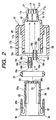
- Fig. 2 is a sectional view showing the waterproof connector in a state before assembled
- Fig. 3 is a sectional view of the essential part of the waterproof connector
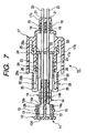
- Fig. 4 is a fragmentary rear view of the essential part partly shown in section
- Fig. 5 is a fragmentary perspective view of the essential part.
- a connector housing 11 of the waterproof connector 10 consists of an inner housing 12 formed of a synthetic resin and including a plurality of terminal chambers 13 integrally formed therewith and arranged both in vertical and lateral directions, an outer housing 17 formed of a synthetic resin into which the inner housing 12 is adapted to be inserted, and a spacer 28 interposed between the inner housing 12 and the outer housing 17 in order to hold female terminals 14 contained in the above described terminal chambers 13 respectively.
- the electric wire through holes 21 are formed in the bottom wall portion 17c of the outer housing 17 at the positions facing with the terminal chambers 13 respectively, and the rubber plug chambers 19 are formed inside the bottom wall portion 17c at the positions facing with the electric wire through holes 21 respectively.
- the rubber plug chambers 19 are arranged in two rows in a vertical direction and in a plurality of rows in a lateral direction.
- the rubber plug exposing holes 17e, 17f, 17g are formed so as to linearly pass through the peripheral wall portion 17d in a vertical direction, and the rubber plug exposing holes 17e, 17f, 17g thus vertically passing are so provided as to extend up to positions adjacent to the electric wire through holes 21 in the bottom wall portion 17c.
- the rubber plugs 18 are adapted to be inserted into the rubber plug chambers 19 in a direction of A which is a direction wherein the inner housing 12 is fitted into the inner wall portion 17a of the outer housing 17 (in a fitting direction of the connector) by way of the spacer 28.
- Each of the rubber plugs 18 is integrally formed at its both ends 18a with extended portions 18b having a smaller diameter and extending up to an inner face of the bottom wall portion 17c of the outer housing 17 and an outer face of the bottom wall portion 28c of the spacer 28.
- An electric wire through hole 18c through which the electric wire 20 passes is formed at the center of the rubber plug 18 between the both ends 18a.
- the middle part of the rubber plug 18 is in a form of undulated cylinder so that the electric wire can be passed therethrough leaving no clearance.
- This waterproof connector 10 is substantially the same as the related waterproof connector 10'' with respect to other structures, the same components will be denoted with the same reference numerals to omit a further explanation.
- the waterproof connector 10 is manufactured in a similar assembling manner to the related waterproof connector 10''.
- the rubber plug exposing holes 17e, 17f and 17g in the peripheral wall portion 17d of the outer housing 17 surrounding the rubber plug chambers 19 at the areas except the areas sealed with respect to the rubber plugs 18 in such a manner that the rubber plug exposing holes 17e, 17f and 17g linearly pass through the peripheral wall portion 17d in a vertical direction, and the rubber plug exposing holes 17e, 17f, 17g thus vertically passing are so provided as to extend up to the positions adjacent to the electric wire through holes 21 in the bottom wall portion 17c.
- the presence of the rubber plugs 18 (lack of components) can be very easily confirmed from the exterior of the outer housing 17 through the vertically passing rubber plug exposing holes 17e, 17f, 17g, even in case where the rubber plug chambers 19 are arranged in two rows in a vertical direction and in a plurality of rows in a lateral direction in the bottom wall portion 17c of the outer housing 17.
- the assembling grade of the waterproof connector 10 can be thus improved.
- the extended portion 18b is integrally formed at the one end 18a of the rubber plug 18 so as to extend up to the inner face of the bottom wall portion 17c of the outer housing 17, the extended portions 18b at the both ends 18a of the rubber plug 18 can be easily observed from the exterior of the outer housing 17 through the rubber plug exposing holes 17e, 17f, 17g.
- the presence of the rubber plugs 18 (lack of components) can be easily confirmed, and the assembling grade of the waterproof connector 10 can be remarkably improved.
- Fig. 6 is a fragmentary rear view of a waterproof connector 10' according to a second embodiment of the invention partly shown in section.
- These rubber plug exposing holes 17e, 17, 17g, 17h are formed so as to linearly pass through the peripheral wall portion 17d in a vertical direction, and the rubber plug exposing holes 17e, 17f, 17g, 17h thus vertically passing are so provided as to extend up to the positions adjacent to the electric wire through holes 21 in the bottom wall portion 17c.
- This waterproof connector 10' is substantially the same as the waterproof connector 10 in the first embodiment with respect to other structures, the same components will be denoted with the same reference numerals to omit a further explanation.
- This waterproof connector 10' attains similar effects to the above described waterproof connector 10.
- the presence of the rubber plugs 18 (lack of components) can be very easily confirmed from the exterior of the outer housing 17 through the vertically passing rubber plug exposing holes 17e, 17f, 17g, 17h even in case where the rubber plug chambers 19 are arranged in three rows in a vertical direction and in a plurality of rows in a lateral direction in the bottom wall portion 17c of the outer housing 17.
- the assembling grade of the waterproof connector 10' can be thus improved.
- a pair of the rubber plug exposing holes are formed at upper and lower positions of the peripheral wall portion surrounding the rubber plug chambers, and an air is introduced through the upper rubber plug exposing holes in order to drain the water through the lower rubber plug exposing holes.
- the rubber plug exposing holes may be provided only at the upper side of the peripheral wall portion in case of confirming the presence of the rubber plugs (lack of components) only, and the rubber plug exposing holes may be provided only at the lower side of the peripheral wall portion in case of draining the water only.
Landscapes
- Connector Housings Or Holding Contact Members (AREA)
Applications Claiming Priority (2)
| Application Number | Priority Date | Filing Date | Title |
|---|---|---|---|
| JP16415099A JP3691288B2 (ja) | 1999-06-10 | 1999-06-10 | 防水コネクタ |
| JP16415099 | 1999-06-10 |
Publications (2)
| Publication Number | Publication Date |
|---|---|
| EP1059697A2 true EP1059697A2 (fr) | 2000-12-13 |
| EP1059697A3 EP1059697A3 (fr) | 2001-08-29 |
Family
ID=15787701
Family Applications (1)
| Application Number | Title | Priority Date | Filing Date |
|---|---|---|---|
| EP00304552A Withdrawn EP1059697A3 (fr) | 1999-06-10 | 2000-05-30 | Connecteur étanche |
Country Status (3)
| Country | Link |
|---|---|
| US (1) | US6375500B1 (fr) |
| EP (1) | EP1059697A3 (fr) |
| JP (1) | JP3691288B2 (fr) |
Cited By (3)
| Publication number | Priority date | Publication date | Assignee | Title |
|---|---|---|---|---|
| EP2525443A1 (fr) * | 2011-05-17 | 2012-11-21 | Sumitomo Wiring Systems, Ltd. | Connecteur latéral pour un véhicule et son procédé de montage |
| EP2475052A3 (fr) * | 2011-01-06 | 2014-06-18 | General Cable Technologies Corporation | Ensemble de connecteur surmoulé à intensité de courant élevée multi-polymérique laminé pour chargement de véhicule électrique hybride enfichable |
| GB2534965A (en) * | 2015-10-16 | 2016-08-10 | Luxonic Lighting Plc | Housing for an electrical connection |
Families Citing this family (14)
| Publication number | Priority date | Publication date | Assignee | Title |
|---|---|---|---|---|
| JP2003133002A (ja) * | 2001-08-17 | 2003-05-09 | Yazaki Corp | コネクタとコネクタハウジング |
| JP4267518B2 (ja) * | 2004-05-13 | 2009-05-27 | 矢崎総業株式会社 | 防水コネクタ |
| JP2006221920A (ja) * | 2005-02-09 | 2006-08-24 | Sumitomo Wiring Syst Ltd | コネクタ |
| JP2008536277A (ja) * | 2005-04-11 | 2008-09-04 | エフシーアイ | 電気コネクタ用グロメットおよびそのようなグロメットを具備した電気コネクタ |
| JP4702034B2 (ja) * | 2005-12-20 | 2011-06-15 | パナソニック株式会社 | スイッチ装置 |
| JP4609857B2 (ja) * | 2006-02-10 | 2011-01-12 | 古河電気工業株式会社 | 防水コネクタ |
| US20100022141A1 (en) * | 2008-07-24 | 2010-01-28 | Wen-Liang Wen | Electrical connector |
| JP2012119085A (ja) * | 2010-11-29 | 2012-06-21 | Sumitomo Wiring Syst Ltd | 防水コネクタ |
| JP5686077B2 (ja) * | 2011-09-10 | 2015-03-18 | 住友電装株式会社 | コネクタ |
| JP6064847B2 (ja) * | 2013-09-17 | 2017-01-25 | 株式会社デンソー | 燃料ポンプ |
| JP6306323B2 (ja) * | 2013-11-11 | 2018-04-04 | 矢崎総業株式会社 | 電線ホルダ |
| JP2015225771A (ja) * | 2014-05-28 | 2015-12-14 | 住友電装株式会社 | 複合型充電用インレット |
| JP2016051634A (ja) * | 2014-09-01 | 2016-04-11 | 住友電装株式会社 | コネクタ |
| DE102015113519A1 (de) * | 2015-08-17 | 2017-02-23 | Phoenix Contact E-Mobility Gmbh | Steckverbinderteil mit einer Entwässerung |
Family Cites Families (11)
| Publication number | Priority date | Publication date | Assignee | Title |
|---|---|---|---|---|
| US3077572A (en) * | 1958-06-30 | 1963-02-12 | Amp Inc | Electrical connector |
| GB8431301D0 (en) * | 1984-12-12 | 1985-01-23 | Amp Great Britain | Lead sealing assembly |
| GB8629112D0 (en) * | 1986-12-05 | 1987-01-14 | Amp Great Britain | Electrical connector housing assembly |
| JPH01146478U (fr) * | 1988-03-31 | 1989-10-09 | ||
| JP3009122B2 (ja) * | 1994-03-03 | 2000-02-14 | 矢崎総業株式会社 | 防水コネクタの防水栓 |
| JP2863083B2 (ja) * | 1994-04-01 | 1999-03-03 | 矢崎総業株式会社 | コネクタ用防水栓 |
| JP4163263B2 (ja) * | 1995-04-06 | 2008-10-08 | 矢崎総業株式会社 | 防水コネクタ |
| JPH09289057A (ja) * | 1996-04-19 | 1997-11-04 | Yazaki Corp | 防水コネクタ |
| JPH10223304A (ja) * | 1997-01-31 | 1998-08-21 | Whitaker Corp:The | 防水型電気コネクタ組立体 |
| JP3530024B2 (ja) * | 1998-03-11 | 2004-05-24 | 矢崎総業株式会社 | 防水コネクタ及び該防水コネクタの組付方法 |
| JP3540156B2 (ja) | 1998-06-10 | 2004-07-07 | 矢崎総業株式会社 | 防水コネクタ及び該防水コネクタの組付方法 |
-
1999
- 1999-06-10 JP JP16415099A patent/JP3691288B2/ja not_active Expired - Fee Related
-
2000
- 2000-05-30 EP EP00304552A patent/EP1059697A3/fr not_active Withdrawn
- 2000-06-12 US US09/591,674 patent/US6375500B1/en not_active Expired - Lifetime
Cited By (4)
| Publication number | Priority date | Publication date | Assignee | Title |
|---|---|---|---|---|
| EP2475052A3 (fr) * | 2011-01-06 | 2014-06-18 | General Cable Technologies Corporation | Ensemble de connecteur surmoulé à intensité de courant élevée multi-polymérique laminé pour chargement de véhicule électrique hybride enfichable |
| EP2525443A1 (fr) * | 2011-05-17 | 2012-11-21 | Sumitomo Wiring Systems, Ltd. | Connecteur latéral pour un véhicule et son procédé de montage |
| GB2534965A (en) * | 2015-10-16 | 2016-08-10 | Luxonic Lighting Plc | Housing for an electrical connection |
| GB2534965B (en) * | 2015-10-16 | 2017-02-15 | Luxonic Lighting Plc | Housing for an electrical connection |
Also Published As
| Publication number | Publication date |
|---|---|
| EP1059697A3 (fr) | 2001-08-29 |
| JP3691288B2 (ja) | 2005-09-07 |
| JP2000353570A (ja) | 2000-12-19 |
| US6375500B1 (en) | 2002-04-23 |
Similar Documents
| Publication | Publication Date | Title |
|---|---|---|
| EP1059697A2 (fr) | Connecteur étanche | |
| US6203348B1 (en) | Waterproof connector and waterproof rubber member | |
| US6494731B1 (en) | Waterproof connector | |
| US8167634B2 (en) | Connector with a sealing ring having a bulge at its inner peripheral side of its main body | |
| US6390848B1 (en) | Engagement structure of waterproof connector and dummy plug | |
| KR910004169B1 (ko) | 커 넥 터 | |
| EP1170828B1 (fr) | Couvercle de protection | |
| US7118423B2 (en) | Joint connector structure | |
| JP3540197B2 (ja) | 防水コネクタ | |
| US6179657B1 (en) | Waterproof connector and method of assembling the same | |
| JP3517107B2 (ja) | 防水コネクタ及び該防水コネクタの組付方法 | |
| EP1056161B1 (fr) | Connecteur étanche à l'eau et procédé de montage | |
| EP0935311A1 (fr) | Connecteur | |
| EP1041678B1 (fr) | Connecteur étanche et procédé d'assemblage | |
| EP1187263B1 (fr) | Connecteur étanche | |
| JPH06181078A (ja) | コネクタの連結構造 | |
| JP3533546B2 (ja) | ジョイントコネクタ | |
| JP2005166293A (ja) | 防水コネクタ | |
| JPH0353539Y2 (fr) | ||
| JP3404995B2 (ja) | ジョイントコネクタ | |
| JP2005203279A (ja) | 防水ジョイントコネクタ | |
| CN113039684A (zh) | 电气连接器组件 | |
| JP2503949Z (fr) |
Legal Events
| Date | Code | Title | Description |
|---|---|---|---|
| PUAI | Public reference made under article 153(3) epc to a published international application that has entered the european phase |
Free format text: ORIGINAL CODE: 0009012 |
|
| AK | Designated contracting states |
Kind code of ref document: A2 Designated state(s): AT BE CH CY DE DK ES FI FR GB GR IE IT LI LU MC NL PT SE Kind code of ref document: A2 Designated state(s): DE FR GB |
|
| AX | Request for extension of the european patent |
Free format text: AL;LT;LV;MK;RO;SI |
|
| PUAL | Search report despatched |
Free format text: ORIGINAL CODE: 0009013 |
|
| AK | Designated contracting states |
Kind code of ref document: A3 Designated state(s): AT BE CH CY DE DK ES FI FR GB GR IE IT LI LU MC NL PT SE |
|
| AX | Request for extension of the european patent |
Free format text: AL;LT;LV;MK;RO;SI |
|
| 17P | Request for examination filed |
Effective date: 20020128 |
|
| AKX | Designation fees paid |
Free format text: DE FR GB |
|
| 17Q | First examination report despatched |
Effective date: 20020524 |
|
| STAA | Information on the status of an ep patent application or granted ep patent |
Free format text: STATUS: THE APPLICATION IS DEEMED TO BE WITHDRAWN |
|
| 18D | Application deemed to be withdrawn |
Effective date: 20030513 |