EP1059904B1 - Autonome und tragbare kryo-vorrichtung mit verwendung von kohlendioxid in fester / flüssiger phase - Google Patents
Autonome und tragbare kryo-vorrichtung mit verwendung von kohlendioxid in fester / flüssiger phase Download PDFInfo
- Publication number
- EP1059904B1 EP1059904B1 EP99937864A EP99937864A EP1059904B1 EP 1059904 B1 EP1059904 B1 EP 1059904B1 EP 99937864 A EP99937864 A EP 99937864A EP 99937864 A EP99937864 A EP 99937864A EP 1059904 B1 EP1059904 B1 EP 1059904B1
- Authority
- EP
- European Patent Office
- Prior art keywords
- appliance
- cartridge
- temperature
- expansion
- liquid
- Prior art date
- Legal status (The legal status is an assumption and is not a legal conclusion. Google has not performed a legal analysis and makes no representation as to the accuracy of the status listed.)
- Expired - Lifetime
Links
- 239000007791 liquid phase Substances 0.000 title claims description 12
- 239000007790 solid phase Substances 0.000 title claims description 6
- CURLTUGMZLYLDI-UHFFFAOYSA-N Carbon dioxide Chemical compound O=C=O CURLTUGMZLYLDI-UHFFFAOYSA-N 0.000 title description 36
- 229910002092 carbon dioxide Inorganic materials 0.000 title description 11
- 239000001569 carbon dioxide Substances 0.000 title description 11
- 239000007788 liquid Substances 0.000 claims description 14
- 238000009527 percussion Methods 0.000 claims description 11
- 238000013459 approach Methods 0.000 claims description 9
- 238000010926 purge Methods 0.000 claims description 9
- 239000007787 solid Substances 0.000 claims description 6
- 229910000906 Bronze Inorganic materials 0.000 claims description 4
- 239000010974 bronze Substances 0.000 claims description 4
- 238000004891 communication Methods 0.000 claims description 4
- KUNSUQLRTQLHQQ-UHFFFAOYSA-N copper tin Chemical compound [Cu].[Sn] KUNSUQLRTQLHQQ-UHFFFAOYSA-N 0.000 claims description 4
- 238000005507 spraying Methods 0.000 claims description 4
- 230000004044 response Effects 0.000 claims description 3
- 238000000926 separation method Methods 0.000 claims description 3
- 230000000007 visual effect Effects 0.000 claims description 3
- 238000009529 body temperature measurement Methods 0.000 claims description 2
- -1 carbon anhydride Chemical class 0.000 claims description 2
- 238000005520 cutting process Methods 0.000 claims description 2
- 239000002245 particle Substances 0.000 claims description 2
- 238000000605 extraction Methods 0.000 claims 4
- 229910052799 carbon Inorganic materials 0.000 claims 2
- 230000003993 interaction Effects 0.000 claims 2
- OKTJSMMVPCPJKN-UHFFFAOYSA-N Carbon Chemical compound [C] OKTJSMMVPCPJKN-UHFFFAOYSA-N 0.000 claims 1
- 238000000315 cryotherapy Methods 0.000 description 13
- 235000011089 carbon dioxide Nutrition 0.000 description 11
- 239000007789 gas Substances 0.000 description 11
- 238000005259 measurement Methods 0.000 description 5
- 206010061218 Inflammation Diseases 0.000 description 4
- 230000004054 inflammatory process Effects 0.000 description 4
- 239000012071 phase Substances 0.000 description 4
- IJGRMHOSHXDMSA-UHFFFAOYSA-N Atomic nitrogen Chemical compound N#N IJGRMHOSHXDMSA-UHFFFAOYSA-N 0.000 description 3
- 241001465754 Metazoa Species 0.000 description 3
- 208000002193 Pain Diseases 0.000 description 3
- 230000009471 action Effects 0.000 description 3
- 208000014674 injury Diseases 0.000 description 3
- 238000010079 rubber tapping Methods 0.000 description 3
- 230000008733 trauma Effects 0.000 description 3
- XKRFYHLGVUSROY-UHFFFAOYSA-N Argon Chemical compound [Ar] XKRFYHLGVUSROY-UHFFFAOYSA-N 0.000 description 2
- 102000004190 Enzymes Human genes 0.000 description 2
- 108090000790 Enzymes Proteins 0.000 description 2
- 230000005540 biological transmission Effects 0.000 description 2
- 230000015572 biosynthetic process Effects 0.000 description 2
- 230000000903 blocking effect Effects 0.000 description 2
- 239000012530 fluid Substances 0.000 description 2
- 238000004519 manufacturing process Methods 0.000 description 2
- 239000000203 mixture Substances 0.000 description 2
- 210000003205 muscle Anatomy 0.000 description 2
- 230000005855 radiation Effects 0.000 description 2
- 230000011514 reflex Effects 0.000 description 2
- 238000007789 sealing Methods 0.000 description 2
- 230000000638 stimulation Effects 0.000 description 2
- 238000000859 sublimation Methods 0.000 description 2
- 230000008022 sublimation Effects 0.000 description 2
- 208000031968 Cadaver Diseases 0.000 description 1
- 208000034656 Contusions Diseases 0.000 description 1
- 206010018852 Haematoma Diseases 0.000 description 1
- 206010021118 Hypotonia Diseases 0.000 description 1
- 208000007101 Muscle Cramp Diseases 0.000 description 1
- 206010030113 Oedema Diseases 0.000 description 1
- 208000006735 Periostitis Diseases 0.000 description 1
- 235000014676 Phragmites communis Nutrition 0.000 description 1
- 208000010040 Sprains and Strains Diseases 0.000 description 1
- 208000000491 Tendinopathy Diseases 0.000 description 1
- 206010043255 Tendonitis Diseases 0.000 description 1
- 208000004760 Tenosynovitis Diseases 0.000 description 1
- 230000001154 acute effect Effects 0.000 description 1
- 230000006978 adaptation Effects 0.000 description 1
- 229910052786 argon Inorganic materials 0.000 description 1
- 230000015556 catabolic process Effects 0.000 description 1
- 230000008859 change Effects 0.000 description 1
- 238000011109 contamination Methods 0.000 description 1
- 208000006111 contracture Diseases 0.000 description 1
- 230000006378 damage Effects 0.000 description 1
- 238000013461 design Methods 0.000 description 1
- 238000005474 detonation Methods 0.000 description 1
- 230000000694 effects Effects 0.000 description 1
- 230000002349 favourable effect Effects 0.000 description 1
- 230000004907 flux Effects 0.000 description 1
- 231100001261 hazardous Toxicity 0.000 description 1
- 230000002757 inflammatory effect Effects 0.000 description 1
- 238000003754 machining Methods 0.000 description 1
- 239000002184 metal Substances 0.000 description 1
- 238000000034 method Methods 0.000 description 1
- 230000036640 muscle relaxation Effects 0.000 description 1
- 210000004126 nerve fiber Anatomy 0.000 description 1
- 229910052757 nitrogen Inorganic materials 0.000 description 1
- 210000000929 nociceptor Anatomy 0.000 description 1
- 108091008700 nociceptors Proteins 0.000 description 1
- 210000000056 organ Anatomy 0.000 description 1
- 239000005416 organic matter Substances 0.000 description 1
- 239000004033 plastic Substances 0.000 description 1
- 239000004810 polytetrafluoroethylene Substances 0.000 description 1
- 229920001343 polytetrafluoroethylene Polymers 0.000 description 1
- 230000009467 reduction Effects 0.000 description 1
- 239000000523 sample Substances 0.000 description 1
- 229920006395 saturated elastomer Polymers 0.000 description 1
- 239000007921 spray Substances 0.000 description 1
- 201000004415 tendinitis Diseases 0.000 description 1
- 238000002560 therapeutic procedure Methods 0.000 description 1
- 210000001519 tissue Anatomy 0.000 description 1
- 230000000451 tissue damage Effects 0.000 description 1
- 231100000827 tissue damage Toxicity 0.000 description 1
- 238000011144 upstream manufacturing Methods 0.000 description 1
- 239000012808 vapor phase Substances 0.000 description 1
- 230000001457 vasomotor Effects 0.000 description 1
Images


Classifications
-
- A—HUMAN NECESSITIES
- A61—MEDICAL OR VETERINARY SCIENCE; HYGIENE
- A61F—FILTERS IMPLANTABLE INTO BLOOD VESSELS; PROSTHESES; DEVICES PROVIDING PATENCY TO, OR PREVENTING COLLAPSING OF, TUBULAR STRUCTURES OF THE BODY, e.g. STENTS; ORTHOPAEDIC, NURSING OR CONTRACEPTIVE DEVICES; FOMENTATION; TREATMENT OR PROTECTION OF EYES OR EARS; BANDAGES, DRESSINGS OR ABSORBENT PADS; FIRST-AID KITS
- A61F7/00—Heating or cooling appliances for medical or therapeutic treatment of the human body
- A61F7/0085—Devices for generating hot or cold treatment fluids
-
- A—HUMAN NECESSITIES
- A61—MEDICAL OR VETERINARY SCIENCE; HYGIENE
- A61B—DIAGNOSIS; SURGERY; IDENTIFICATION
- A61B18/00—Surgical instruments, devices or methods for transferring non-mechanical forms of energy to or from the body
- A61B18/02—Surgical instruments, devices or methods for transferring non-mechanical forms of energy to or from the body by cooling, e.g. cryogenic techniques
- A61B18/0218—Surgical instruments, devices or methods for transferring non-mechanical forms of energy to or from the body by cooling, e.g. cryogenic techniques with open-end cryogenic probe, e.g. for spraying fluid directly on tissue or via a tissue-contacting porous tip
-
- F—MECHANICAL ENGINEERING; LIGHTING; HEATING; WEAPONS; BLASTING
- F16—ENGINEERING ELEMENTS AND UNITS; GENERAL MEASURES FOR PRODUCING AND MAINTAINING EFFECTIVE FUNCTIONING OF MACHINES OR INSTALLATIONS; THERMAL INSULATION IN GENERAL
- F16C—SHAFTS; FLEXIBLE SHAFTS; ELEMENTS OR CRANKSHAFT MECHANISMS; ROTARY BODIES OTHER THAN GEARING ELEMENTS; BEARINGS
- F16C7/00—Connecting-rods or like links pivoted at both ends; Construction of connecting-rod heads
- F16C7/02—Constructions of connecting-rods with constant length
-
- F—MECHANICAL ENGINEERING; LIGHTING; HEATING; WEAPONS; BLASTING
- F25—REFRIGERATION OR COOLING; COMBINED HEATING AND REFRIGERATION SYSTEMS; HEAT PUMP SYSTEMS; MANUFACTURE OR STORAGE OF ICE; LIQUEFACTION SOLIDIFICATION OF GASES
- F25D—REFRIGERATORS; COLD ROOMS; ICE-BOXES; COOLING OR FREEZING APPARATUS NOT OTHERWISE PROVIDED FOR
- F25D3/00—Devices using other cold materials; Devices using cold-storage bodies
- F25D3/10—Devices using other cold materials; Devices using cold-storage bodies using liquefied gases, e.g. liquid air
Definitions
- the apparatus provides inside a bottle of pressurized liquefied carbon dioxide, to install from the head of the bottle, a dip tube extending over all the length of the bottle.
- a dip tube extending over all the length of the bottle.
- an autonomous, light and portable apparatus capable of producing intense cold providing a very rapid temperature drop, and this, under conditions of maximum thermal safety.
- the projection of dry ice on the skin of a patient must be strictly controlled, insofar as the surface temperature at the level of the skin must never drop below 0 ° C to avoid damage organic tissue.
- the temperature of the area thus treated is measured without contact with the patient but in direct contact with the portable device in order to avoid handling which would considerably slow down the intervention.
- a portable cryogenic device primarily using the expansion temperature (of the order of -78 ° C at atmospheric pressure) of carbon dioxide (CO 2 ) or equivalent in liquid / solid phase comprising a tank of pressurized liquefied CO 2 , the head of which is connected to an expansion and ejection system of liquid / solid CO 2 , and comprising command, expansion and control members for temperature of the area of use, which is remarkable in that the head of the CO 2 reservoir is arranged on the device in such a way that during the entire period of use, only the liquid part of the CO 2 inside of the reservoir comes into contact with said head to be withdrawn there and propelled towards the zone of use by means of an expansion and ejection system.
- CO 2 carbon dioxide
- the apparatus according to the invention is characterized in that the tank advantageously having the general shape of a conventional compressed gas cartridge provided with a special tapping head at its end comprising means of securing and separation from the device and from the setting members communication with its expansion and ejection system, is located above the device, when it is in intervention position, the cartridge being inclined in the vertical plane and the tapping head being turned towards down toward the device it's on secured.
- the apparatus is planned to equip it with a temperature measurement system in order to warn the operator when the temperature of area of the use area has reached a threshold critical for example in cryotherapy when the skin is approaches 0 ° C.
- cryotherapy can be grouped into three categories: resistive probes, patches thermo-sensitive stickers or pyrometers to distance and in particular infrared pyrometers; the latter category, operating on the principle that every body emits radiation proportional to its temperature at power 4, corresponds well to the character autonomous and portable of the device according to the invention; in furthermore, infrared pyrometers are quite capable perform extremely fast measurements, related precise with the treatment area, subject however to provide a power supply and to adapt well the focal length of the pyrometer; we know that if the treatment distance is too short (e.g.
- the thermal gradient of the skin undergoing cryotherapy is so important that the temperature of the treated area and the temperature of the area scanned by the pyrometer are then very distant, which does not allow the implementation audible or visible alarm, with the consequence of a setting in danger of the subject treated.
- the approach guide will consist of a simple sliding rod giving the distance between the pyrometer and the area to be treated; this rod can also contribute to device security; for example, putting under device voltage can only be obtained when this same rod will be placed in the external measurement position, as explained below; in this way we limit the untimely use by children, in particular.
- infrared pyrometers it is entirely possible for a person skilled in the art to calculate the focal distance of the pyrometer in such a way that the measurement spot on the part to be treated is always outside the area of projection of the dry ice, so that the measurement is done well on a treated area and does not take the temperature of the dry ice, which would be the case if the measurement spot was superimposed on the sublimation area of CO 2 .
- cryogenic device 1 which will now be described is particularly intended to cryotherapy in humans or animals.
- the device 1 has the general shape of a gun made in a plastic shell arranged internally to contain the functional organs of the device 1; this is supplied by a CO 2 cartridge in liquid phase, introduced at the rear at a vertical inclination which will be specified below.
- the body 100 of the gun receiving the cryogenic expansion chain of the gun comprises at the rear a support 3 receiving on one side the withdrawal head 4 of the cartridge 2 via a connecting piece 5, and l 'other side, a filter 6 which will be specified below, an in-line solenoid valve 7 putting carbon dioxide CO 2 in communication with an expansion and ejection tube 8 bent to lead to the front end 9 of the barrel 101 substantially horizontal and project the CO 2 in liquid / solid phase towards the area of use (not shown in the figures).
- the solenoid valve 7 operating in "all or nothing” mode is of a fully known type, for example available in the catalog of the Swiss company "Fluid Automation Systems". It is supplied under continuous voltage of 12 volts by a set of batteries 10 conventionally arranged inside the butt 11 serving as a handle for the gun 1, according to a stack of elements giving maximum electrical operating safety. Naturally, to actuate the solenoid valve 7 and consequently distribute the CO 2 in liquid / solid form at the outlet point 9 of the gun, it is necessary to actuate a switch 12 disposed at the front of the butt 11, in the manner of a conventional trigger by the index finger of the user holding the gun 1.
- a rod 13 as an approach guide can slide horizontally from a rest position (shown in Figure 1 in solid lines), inside the barrel 101 to a working position (including the rear part, internal to the pistol, is shown in thin dashed lines on the figure 1) corresponding to the suitable distance for a optimal projection of dry ice on the area to be treated but also for a fair and precise thermal control of said zone by means of an infrared pyrometer 14 (shown in Figures 2 and 3) as will be said more far.
- a reed switch 15 is provided at inside the gun barrel 1 to be normally open until rod 13 is not fully pulled towards outside, i.e. in working position for the pistol; as soon as the rod 13 is fully pulled out, the switch 15 is in the closed position thanks to a boss 132 arranged at the internal end of the rod 13 then turning on the infrared pyrometer of a part, and authorizing the triggering of the solenoid valve 7 by action of the control switch 12.
- the cryogenic gun 1 usable especially in cryotherapy applied to humans or animals moreover is particularly indicated in emergencies sports to treat pain, bruising, sprains, edemas, hematomas, breakdowns muscle, cramps, contractures, dislocations acromioclavicular, or in acute care for treat reaction inflammations, tendonitis, bursites, and other tenosynovitis, periostitis, etc ...
- Said device taken in hand by the user thanks to its ergonomic stock 11 is normally held in such a way that the barrel 101 of the pistol 1 is substantially horizontal, which has the automatic effect of constantly keeping the cartridge 2 upside down, with a vertical inclination ⁇ d ' at least 15 ° from the horizontal plane ensuring at the time of use, to draw from the cartridge 2 only CO 2 in the liquid phase and in no case, in the vapor phase.
- the operator then actuates the switch 12 in the manner of a trigger to control the solenoid valve 7 and withdraw the liquid CO 2 from the cartridge 2 to bring it through the expansion tube 8 towards the end 9 and the spray, onto the treatment area, in the form of dry ice, by a continuous and crossed sweep over the area to be treated; the dry ice on the patient's skin is then sublimated and creates a very strong lowering of temperature by removing calories during the sublimation operation as has been said.
- the infrared pyrometer 14 When the infrared pyrometer 14, operating as will be said later, detects that the temperature of the treated area approaches 2 ° C, it gives a setpoint to the electronics 17 which alerts the user to an imminent danger of burns thanks to a sound and / or light alarm device such as for example an LED 18 (FIGS. 1, 2 and 3); when the LED 18 flashes, it is enough to slightly spread the gun so as to avoid in all cases going below 0 ° C at the level of the patient's skin; generally the duration of treatment is around 30 to 50 seconds.
- a sound and / or light alarm device such as for example an LED 18 (FIGS. 1, 2 and 3)
- the LED 18 flashes, it is enough to slightly spread the gun so as to avoid in all cases going below 0 ° C at the level of the patient's skin; generally the duration of treatment is around 30 to 50 seconds.
- the visual alarm 18 controlled by the infrared pyrometer 14 could be replaced or supplemented by an audible alarm anyway that those skilled in the art would be able to adapt without difficulty; likewise, it is obvious that for quite uses occasional, it may be possible to use the deposit infrared pyrometer 14, when it has detected that the treatment area reached 2 ° C, to order automatically power the device thus blocking the projection of dry ice; all others adaptations of the same type would naturally enter the part of the invention.
- the cartridge of CO 2, medicalized if necessary and liquefied under pressure is in fact a cartridge conventionally comprising a metal container of cylindrical shape quite analogous to that which is encountered in many equipment such as fire extinguishers, provided with a racking head, arranged to cooperate with a support for use.
- This cartridge can be disposable or refillable, that is to say sold and subsequently recharged by gas companies in a completely known manner.
- the pistol According to a preferred embodiment of the pistol according to the invention, it will be equipped with disposable cartridges containing 160 g of CO 2 corresponding to a treatment of 40 to 50 seconds and dispensing users from having to resort to heavy logistics to reload the empty bottles.
- the thread of the nut 5 coming to be screwed above the tapping head 4 of the cartridge 2 was deliberately chosen from not very common steps so that it is not possible to use cartridges not suitable for the gun 1.
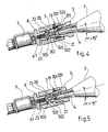
- the cartridge percussion system 2. is broken down into three parts in accordance with FIGS. 4 and 5.
- a cylindrical support 3 comprising on the cartridge side a first internally threaded inlet chamber 301, into which the nut 5 previously mounted on is screwed the withdrawal head 4 of the cartridge 2 which is closed by a bronze cover 201; in the axis of this first chamber 301 and emerging therein, a second chamber 302 of smaller diameter comes to collaborate with the end 501 of the nut 5 of smaller diameter than the threaded part of said nut in order to ensure a total seal , thanks to an external O-ring 502 mounted on said end 501 between the cartridge 2 and the rest of the device as soon as the striker 20 pierces the bronze cap 201.
- the striker 20 forming the second part of the system consists of a tip 21 fixed and integral with the support 3 which can engage in the hollow end portion 503 of the nut 5 surrounding the withdrawal head 4 until it comes into contact with the seal 201 when the engagement of said nut 5 in the support 3 is sufficient to secure the assembly of the assembly; at this instant, the tip 21 is in contact with the cover 201 and the O-ring 202 is in contact with the walls of the chamber 302 ensuring its tightness with the withdrawal head 4; it then suffices, as shown in FIG.
- the latter chosen from high-pressure solenoid valves, allows the opening and closing of an axial channel extending the previous 61 by simple electrical control of an electromagnet disposed in the axis of the solenoid valve.
- a slightly curved expansion tube 8 is mounted according to a well-known assembly to compensate for the inclination ⁇ of the cartridge on its support 3, thus connecting the uncapped sealing head 4 to the ejection point 9 of the gun 1.
- the expansion tube 8 is given a very small internal diameter, of the order of 0.5 mm.
- a PTFE tube is preferably used.
- the flow speed of the CO 2 inside the expansion tube 8 is sufficiently high to evacuate to the outside the dry ice micronized particles sublimating in the area of use or the area of care.
- this purge hole 19 (figure 4) purges the residual gas when you remove the cartridge 2 by unscrewing the nut 5 of its housing in room 301 of the support 3; naturally the inner geometry of this room 301 was provided so that as soon as the head uncapped of the cartridge 2 emerges from the tip of percussion 21, the residual gas is in contact with the hole purge 19, i.e. with the outside, even though the length of the thread of the nut 5 still engaged in the chamber 301 is still sufficient to rigidly hold the assembly and avoid any sudden retreat of the cartridge freed from its support; it will therefore suffice as soon as the gas hissing through the bleed hole 19 appears, wait until it stops to continue unscrewing the nut 5 and remove the cartridge 2 for its replacement.
- the gun 1 which has just been described is further supplemented by a member for controlling the temperature of the area of use in order to prevent the lowering of temperature favorable for the treatment does not cause tissue damage; for this purpose and according to a preferred embodiment of the invention, there is provided on the gun parallel to its barrel 101 incorporating the CO 2 expansion chain a second barrel 102 receiving a temperature threshold detector 14 and its control electronics 17 able to operate remotely without contact with the area of use or care, in accordance with Figures 2 and 3 of the drawings.
- an infrared pyrometer 14 is preferably chosen as the temperature threshold detector associated with the pistol, operating preferably with a continuous supply of 12 volts as the solenoid valve. 7; the optics of the pyrometer 14 is arranged in such a way that the field of vision corresponds as completely as possible to the target to be measured on the area of use or on the skin in order to obtain a fair and precise temperature reading.
- the optics of the pyrometer 14 is calculated so that a target diameter of 15 mm on the treatment zone corresponds to a focusing spot on the detector having a diameter of approximately 1 mm, and this, taking into account 'A distance between the lens of the pyrometer and the target between 120 and 150 mm corresponding, as we have seen, to an optimal position of the device relative to the area of use; indeed, if the treatment distance is too short, the thermal gradient of the skin becomes so large that the temperature of the treated area and the temperature of the area scanned by the pyrometer are very far away, with the consequence of making the set point random alarm.
- the threshold detector of the pyrometer 14 is adjusted to the fixed temperature of + 2 ° C to maintain a margin of safety with respect to the critical temperature of 0 ° C as it has already been said.
- the pyrometer 14 is coupled to electronics 17 ( Figure 3) also working under a 12 volt supply for example as soon as the approach guide 13 is fully pulled out of the pistol; so it is possible to adjust the emissivity of the detector defined as the ratio of energy radiated by the treatment area whose temperature and energy emitted by a black body at the same temperature.
- the skin which is an organic matter we know that its emissivity is 0.95, so the pyrometer 14 will be preset to this value.
- the pyrometer must respond quickly enough to check the temperature ; however, the response time of the pyrometer must not be too short in order to clip the values temperature extremes when necessary scanning of the treated surface as said above high. Under these conditions, the response time will be preset to around 5 seconds.
- the electronics 17 trips an audible and / or visual alarm such as an LED 18 so to warn the user either to stop spraying, either temporarily remove gun 1 from the treatment.
- an audible and / or visual alarm such as an LED 18 so to warn the user either to stop spraying, either temporarily remove gun 1 from the treatment.
Landscapes
- Engineering & Computer Science (AREA)
- Health & Medical Sciences (AREA)
- General Engineering & Computer Science (AREA)
- Surgery (AREA)
- Life Sciences & Earth Sciences (AREA)
- Public Health (AREA)
- Veterinary Medicine (AREA)
- Heart & Thoracic Surgery (AREA)
- Biomedical Technology (AREA)
- Mechanical Engineering (AREA)
- Animal Behavior & Ethology (AREA)
- General Health & Medical Sciences (AREA)
- Nuclear Medicine, Radiotherapy & Molecular Imaging (AREA)
- Chemical & Material Sciences (AREA)
- Otolaryngology (AREA)
- Molecular Biology (AREA)
- Medical Informatics (AREA)
- Combustion & Propulsion (AREA)
- Physics & Mathematics (AREA)
- Thermal Sciences (AREA)
- Vascular Medicine (AREA)
- Thermotherapy And Cooling Therapy Devices (AREA)
- Filling Or Discharging Of Gas Storage Vessels (AREA)
- Surgical Instruments (AREA)
- Shafts, Cranks, Connecting Bars, And Related Bearings (AREA)
- Freezing, Cooling And Drying Of Foods (AREA)
Claims (15)
- Autonomes Kryo-Gerät (1) mit hauptsächlicher Verwendung der Entspannungstemperatur von Kohlendioxid (CO2) in flüssiger/fester Phase oder ähnlichem, das einen Behälter (2) für verflüssigtes CO2 unter Druck umfasst, dessen Entnahmekopf (4) mit einem System zur Entspannung und zum Ausstoß von flüssigem/festem CO2 so verbunden ist, dass während der gesamten Nutzungsdauer nur der flüssige Teil des CO2 im Innern des Behälters (2) mit dem besagten Kopf (4) in Kontakt tritt, um dort entnommen und in Richtung des Anwendungsbereichs getrieben zu werden, und Steuereinrichtungen zur Entspannung und Überprüfung der Temperatur im Anwendungsbereich, dadurch gekennzeichnet, dass sich der allgemein als Patrone (2) geformte Behälter für komprimiertes Gas, der an seinem Ende mit dem Mittel (3, 5) zur Verbindung und Lösen der Verbindung mit dem Gerät (1) und Organen (6, 7) zur Herstellung der Kommunikation mit seinem Entspannungs- und Ausstoßsystem (8) aufweisenden Entnahmekopf (4) versehen ist, oberhalb des Geräts (1) befindet, wenn sich dieses in etwa waagerechter Position befindet, d. h. für einen Eingriff in die Hand genommen wird, wobei die Achse der Patrone (2) dann senkrecht geneigt ist und der Entnahmekopf (4) nach unten in Richtung des Geräts, mit dem er verbunden ist, gerichtet wird.
- Gerät nach Anspruch 1, dadurch gekennzeichnet, dass die Mittel angeordnet sind, damit die senkrechte Neigung der Achse der Patrone in bezug auf die waagerechte Ebene während des Eingriffs mindestens 15 Grad beträgt.
- Gerät nach einem der Ansprüche 1 oder 2, dadurch gekennzeichnet, dass der Entnahmekopf (4) der Patrone (2), der von einem zylindrischen, außen mit einem Gewinde versehenen Endstück gebildet wird, das von einem zum Beispiel aus Bronze bestehenden Verschlussorgan (201) verschlossen wird, mit dem Patronenhalter (3) im Gerät mittels eines Teils (5) verbunden wird, das die Montage gewährleistet, wenn die Patrone (2) in den Halter (3) eingeschraubt ist, um zunächst das Verschlussorgan (201) in Kontakt mit einem vorteilhafterweise festen Organ (21) zur Perkussion (20) zu führen, das sich in der Achse des Halters (3) erstreckt, um dann das besagte Verschlussorgan bei Gewährleistung der Dichtigkeit des Aufbaus zu durchstoßen, um das CO2 in flüssiger Phase durch einen die Perkussionsvorrichtung (20) ganz durchquerenden axialen Kanal (22) zu entnehmen, der an seinem freien Ende mit dem Entspannungssystem (8) verbunden ist, wobei eine Entlüftungsöffnung (19) zwischen dem Innenraum des Halters (3) und außen radial in dem Teil (301) des besagten Halters vorgesehen ist, der kein Perkussionsorgan (21) aufweist, um das restliche CO2 in der leeren Patrone beim Abschrauben und vor deren vollständiger Trennung vom Gerät abzulassen.
- Gerät nach einem der Ansprüche 1, 2 oder 3, dadurch gekennzeichnet, dass das Kommunikationsorgan zwischen der Patrone (2) und dem Entspannungssystem (8) ein Elektroventil (7) ist, vorzugsweise in Reihe, das nach dem Prinzip "alles oder nichts" funktioniert.
- Gerät nach einem der vorhergehenden Ansprüche, dadurch gekennzeichnet, dass das System zur Entspannung des flüssigen CO2 oder ähnlichem und zum Ausstoß (9) des festen CO2 oder ähnlichem von einem Rohrstutzen (8) mit einem kleinen Innendurchmesser in der Größenordnung von 0,5 mm gebildet wird, in dem die Strömungsgeschwindigkeit des CO2 oder ähnlichem ausreichend groß ist, um das feste CO2 oder ähnliches in mikronisierten Teilchen nach außen zu befördern, die sich im Anwendungsbereich sublimieren.
- Gerät nach einem der vorhergehenden Ansprüche, durch seine allgemeine Pistolenform (1) gekennzeichnet, umfassend mindestens eine Schale, die die Patrone (2) hinten aufnimmt, einen Lauf (101) und einen Kolben (11) mit einem Abzug (12) zur allgemeinen Steuerung, dessen Ergonomie dergestalt ist, dass, wenn die Pistole (1) vom Anwender normal in der Hand gehalten wird, der Lauf (101) etwa waagerecht ist und die Patrone (2) automatisch in einem Winkel α mit dem Kopf nach unten gehalten wird, wobei sich diese Neigung bei der Anwendung weiter akzentuieren kann.
- Gerät nach Anspruch 6, dadurch gekennzeichnet, dass man im Lauf (101) den nach hinten überstehenden Patronenhalter (3) platziert und alle Organe (4, 5, 6, 7, 8) der vorn (9) im System zum Ausstoß des flüssigen CO2 oder ähnlichem endenden Entspannungskette, dadurch, dass man im Kolben die Organe zur Versorgung und Steuerung platziert, nämlich die Versorgungsbatterien (10) und anstelle des Abzugs einen Schalter (12) zum Ausstoß, und dadurch, dass man parallel zum Lauf (101) einen Fühler (14) zum Fühlen der Temperatur im Anwendungsbereich anbringt, der vorzugsweise genau hinter dem Ausstoßpunkt (9) liegt, um jedwede Beeinflussung zwischen der Funktionsweise des Fühlers (14) und dem angetriebenen CO2-Strom oder ähnlichem zu vermeiden.
- Gerät nach einem der vorhergehenden Ansprüche, dadurch gekennzeichnet, dass das Organ zur Kontrolle der Temperatur im Anwendungsbereich kontaktlos zu dieser ist.
- Gerät nach dem vorhergehenden Anspruch, dadurch gekennzeichnet, dass der Fühler des Temperaturkontrollorgans ein Infrarot-Pyrometer (14) ist.
- Gerät nach Anspruch 9, dadurch gekennzeichnet, dass die Fokaldistanz des Infrarot-Pyrometers (14) einerseits so ist, dass es keine Wechselwirkung mit der Zerstäubung des Trockeneises gibt, und andererseits, dass die präzise Temperaturmessung erfolgt, wenn das Gerät (1) in einem für die beabsichtigte Anwendung angemessenen Abstand positioniert ist.
- Gerät nach Anspruch 10, dadurch gekennzeichnet, dass der angemessene Abstand zwischen dem Gerät (1) und dem Anwendungsbereich von einer Näherungsführung vorgegeben wird.
- Gerät nach Anspruch 11, dadurch gekennzeichnet, dass die Näherungsführung von einem unter dem Lauf (101) der Pistole (1) angeordneten Stab (13) gebildet wird, der aus einer Ruheposition im Lauf in eine Arbeitsposition außerhalb des Laufs verschoben wird, die einem für eine optimale Projizierung des CO2 in flüssiger/fester Phase oder ähnlichem angemessenen Abstand entspricht.
- Gerät nach Anspruch 12, dadurch gekennzeichnet, dass der Stab (13), der zu diesem Zweck mindestens mit einem bei seiner Verschiebung als Ausgangsanschlag (131) dienenden Buckel (132) versehen ist, mit einem elektrischen Schalter (15) zusammenwirkt, dessen Verschluss durch den besagten Buckel (132) erzielt wird, damit das Gerät unter Spannung gesetzt werden darf.
- Gerät nach einem der Ansprüche 9 bis 13, dadurch gekennzeichnet, dass das Infrarot-Pyrometer mit einem visuellen und/oder akustischen Alarm (18) gekoppelt ist, wenn der Temperaturabfall im Anwendungsbereich die Schwelle von 2 °C erreicht, wobei das Pyrometer dann vorteilhafter-, aber nicht notwendigerweise die elektrische Versorgung des Geräts automatisch abschalten kann.
- Gerät nach einem der Ansprüche 9 bis 14, dadurch gekennzeichnet, dass man das Pyrometer (14) für einen Zieldurchmesser von gleich ca. 15 mm im Anwendungsbereich auf einen Emissionsgrad von 0,95 und eine Reaktionszeit von 5 Sekunden einstellt und man eine Optik für einen Fokalabstand von inklusive 120 bis 150 mm wählt.
Applications Claiming Priority (3)
| Application Number | Priority Date | Filing Date | Title |
|---|---|---|---|
| FR9802757 | 1998-03-06 | ||
| FR9802757A FR2775589B1 (fr) | 1998-03-06 | 1998-03-06 | Appareil autonome et portable de cryogenie utilisant l'anhydride carbonique en phase liquide/solide |
| PCT/FR1999/000508 WO1999044551A1 (fr) | 1998-03-06 | 1999-03-05 | Appareil autonome et portable de cryogenie utilisant l'anhydride carbonique en phase liquide/solide |
Publications (2)
| Publication Number | Publication Date |
|---|---|
| EP1059904A1 EP1059904A1 (de) | 2000-12-20 |
| EP1059904B1 true EP1059904B1 (de) | 2004-07-21 |
Family
ID=9523747
Family Applications (1)
| Application Number | Title | Priority Date | Filing Date |
|---|---|---|---|
| EP99937864A Expired - Lifetime EP1059904B1 (de) | 1998-03-06 | 1999-03-05 | Autonome und tragbare kryo-vorrichtung mit verwendung von kohlendioxid in fester / flüssiger phase |
Country Status (12)
| Country | Link |
|---|---|
| US (1) | US6141985A (de) |
| EP (1) | EP1059904B1 (de) |
| JP (1) | JP4049358B2 (de) |
| AR (1) | AR018581A1 (de) |
| AT (1) | ATE271368T1 (de) |
| AU (1) | AU750503B2 (de) |
| BR (1) | BR9908790A (de) |
| DE (1) | DE69918810T2 (de) |
| ES (1) | ES2226416T3 (de) |
| FR (1) | FR2775589B1 (de) |
| SA (1) | SA99191310B1 (de) |
| WO (1) | WO1999044551A1 (de) |
Families Citing this family (117)
| Publication number | Priority date | Publication date | Assignee | Title |
|---|---|---|---|---|
| US6726693B2 (en) * | 2000-11-10 | 2004-04-27 | Pearl Technology Holdings, Llc | Tissue resurfacing using biocompatible materials |
| JP3247675B2 (ja) * | 1999-02-03 | 2002-01-21 | 角林商事株式会社 | ドライアイス生成装置 |
| US6705194B2 (en) * | 2000-09-20 | 2004-03-16 | Jet Energy, Inc. | Selfrechargeable gun and firing procedure |
| FR2815246B1 (fr) | 2000-10-13 | 2003-01-24 | Cryonic Medical | Appareil autonome et portable de cryotherapie a usage grand public |
| ES2311504T3 (es) * | 2001-05-16 | 2009-02-16 | N.V. H&O EQUIPMENTS | Instrumento destinado a tratamientos criogenicos en el sector medico, paramedico y cosmetico. |
| WO2004045434A2 (fr) * | 2002-11-18 | 2004-06-03 | N.V. H & O Equipments | Instrument destine aux traitements cryogeniques dans le secteur medical, paramedical et cosmetique |
| US7572255B2 (en) * | 2004-02-03 | 2009-08-11 | Covidien Ag | Gas-enhanced surgical instrument |
| US7628787B2 (en) | 2004-02-03 | 2009-12-08 | Covidien Ag | Self contained, gas-enhanced surgical instrument |
| JP4605809B2 (ja) * | 2004-06-27 | 2011-01-05 | シュタインファット ディーター | 極低温の液化ガスを微調量するための低温媒体調量装置 |
| US7713266B2 (en) | 2005-05-20 | 2010-05-11 | Myoscience, Inc. | Subdermal cryogenic remodeling of muscles, nerves, connective tissue, and/or adipose tissue (fat) |
| US7850683B2 (en) | 2005-05-20 | 2010-12-14 | Myoscience, Inc. | Subdermal cryogenic remodeling of muscles, nerves, connective tissue, and/or adipose tissue (fat) |
| US8478386B2 (en) | 2006-01-10 | 2013-07-02 | Accuvein Inc. | Practitioner-mounted micro vein enhancer |
| US8838210B2 (en) * | 2006-06-29 | 2014-09-16 | AccuView, Inc. | Scanned laser vein contrast enhancer using a single laser |
| US11253198B2 (en) | 2006-01-10 | 2022-02-22 | Accuvein, Inc. | Stand-mounted scanned laser vein contrast enhancer |
| US10238294B2 (en) | 2006-06-29 | 2019-03-26 | Accuvein, Inc. | Scanned laser vein contrast enhancer using one laser |
| US12408865B2 (en) | 2006-01-10 | 2025-09-09 | Accuvein Inc. | Vein imaging device with differential image resolution at the center and the extremities of the vein image |
| US8255040B2 (en) | 2006-06-29 | 2012-08-28 | Accuvein, Llc | Micro vein enhancer |
| US12089951B2 (en) | 2006-01-10 | 2024-09-17 | AccuVeiw, Inc. | Scanned laser vein contrast enhancer with scanning correlated to target distance |
| US12471844B2 (en) | 2006-06-29 | 2025-11-18 | Accuvein, Inc. | Scanned laser vein contrast enhancer with full stopping of scanner movement during scan line reversals |
| US8489178B2 (en) | 2006-06-29 | 2013-07-16 | Accuvein Inc. | Enhanced laser vein contrast enhancer with projection of analyzed vein data |
| US9492117B2 (en) | 2006-01-10 | 2016-11-15 | Accuvein, Inc. | Practitioner-mounted micro vein enhancer |
| US9854977B2 (en) | 2006-01-10 | 2018-01-02 | Accuvein, Inc. | Scanned laser vein contrast enhancer using a single laser, and modulation circuitry |
| US11278240B2 (en) | 2006-01-10 | 2022-03-22 | Accuvein, Inc. | Trigger-actuated laser vein contrast enhancer |
| US10813588B2 (en) | 2006-01-10 | 2020-10-27 | Accuvein, Inc. | Micro vein enhancer |
| US12295744B2 (en) | 2006-01-10 | 2025-05-13 | Accuvein, Inc. | Micro vein enhancer with two lasers and two optical detectors configured for removing surface topology |
| US20100256620A1 (en) * | 2006-01-12 | 2010-10-07 | Galil Medical Ltd. | Thin flexible cryoprobe operated by krypton |
| US8244333B2 (en) * | 2006-06-29 | 2012-08-14 | Accuvein, Llc | Scanned laser vein contrast enhancer |
| US8594770B2 (en) | 2006-06-29 | 2013-11-26 | Accuvein, Inc. | Multispectral detection and presentation of an object's characteristics |
| US8730321B2 (en) | 2007-06-28 | 2014-05-20 | Accuvein, Inc. | Automatic alignment of a contrast enhancement system |
| US8463364B2 (en) | 2009-07-22 | 2013-06-11 | Accuvein Inc. | Vein scanner |
| US20080027419A1 (en) * | 2006-07-25 | 2008-01-31 | Ams Research Corporation | Cryoprobe with Integral Agent Delivery Device |
| US9050117B2 (en) * | 2006-08-28 | 2015-06-09 | The Regents Of The University Of California | Dynamic cooling of human skin using a nontoxic cryogen with no ozone depletion and minimal global warming potential |
| US9254162B2 (en) | 2006-12-21 | 2016-02-09 | Myoscience, Inc. | Dermal and transdermal cryogenic microprobe systems |
| US8409185B2 (en) | 2007-02-16 | 2013-04-02 | Myoscience, Inc. | Replaceable and/or easily removable needle systems for dermal and transdermal cryogenic remodeling |
| DE102007027786A1 (de) | 2007-06-16 | 2008-12-18 | Damm, Hans | Ventil in einer Vorrichtung für die Kryotherapie |
| US8298216B2 (en) | 2007-11-14 | 2012-10-30 | Myoscience, Inc. | Pain management using cryogenic remodeling |
| US8409184B2 (en) * | 2009-09-09 | 2013-04-02 | Cpsi Holdings Llc | Cryo-medical injection device and method of use |
| US20100087806A1 (en) * | 2008-10-07 | 2010-04-08 | Vandolay, Inc. | Automated Cryogenic Skin Treatment |
| KR20110119640A (ko) | 2008-12-22 | 2011-11-02 | 마이오우사이언스, 인크. | 냉매 공급원과 전원이 통합된 한랭수술 시스템 |
| US20100168726A1 (en) * | 2008-12-31 | 2010-07-01 | Marc Arthur Brookman | Cryogenic Dispensing System and Method for Treatment of Dermatological Conditions |
| US9061109B2 (en) | 2009-07-22 | 2015-06-23 | Accuvein, Inc. | Vein scanner with user interface |
| DE102010016458B4 (de) | 2010-04-15 | 2011-12-15 | Ingo Dreher | Handgeführte Kühlvorrichtung zur Kryotherapie |
| ES2759611T3 (es) | 2011-02-01 | 2020-05-11 | Channel Medsystems Inc | Aparato para el tratamiento criogénico de una cavidad o luz del cuerpo |
| CN104010598B (zh) | 2011-09-05 | 2015-12-09 | 库尔诊疗公司 | 用于引起治疗性低体温的冻雾胃递送、皮肤递送或腹膜递送 |
| WO2013106860A1 (en) | 2012-01-13 | 2013-07-18 | Myoscience, Inc. | Cryogenic probe filtration system |
| US9241753B2 (en) | 2012-01-13 | 2016-01-26 | Myoscience, Inc. | Skin protection for subdermal cryogenic remodeling for cosmetic and other treatments |
| WO2013106859A1 (en) | 2012-01-13 | 2013-07-18 | Myoscience, Inc. | Cryogenic needle with freeze zone regulation |
| US9017318B2 (en) | 2012-01-20 | 2015-04-28 | Myoscience, Inc. | Cryogenic probe system and method |
| US9717546B2 (en) | 2012-05-21 | 2017-08-01 | Jhpiego Corporation | Cryotherapy device and method for the treatment of cervical precancerous lesions |
| DE102012013534B3 (de) | 2012-07-05 | 2013-09-19 | Tobias Sokolowski | Vorrichtung für repetitive Nervenstimulation zum Abbau von Fettgewebe mittels induktiver Magnetfelder |
| US9072426B2 (en) | 2012-08-02 | 2015-07-07 | AccuVein, Inc | Device for detecting and illuminating vasculature using an FPGA |
| US10517483B2 (en) | 2012-12-05 | 2019-12-31 | Accuvein, Inc. | System for detecting fluorescence and projecting a representative image |
| US9668800B2 (en) | 2013-03-15 | 2017-06-06 | Myoscience, Inc. | Methods and systems for treatment of spasticity |
| US9610112B2 (en) | 2013-03-15 | 2017-04-04 | Myoscience, Inc. | Cryogenic enhancement of joint function, alleviation of joint stiffness and/or alleviation of pain associated with osteoarthritis |
| US9295512B2 (en) | 2013-03-15 | 2016-03-29 | Myoscience, Inc. | Methods and devices for pain management |
| CN105208954B (zh) | 2013-03-15 | 2019-06-04 | 肌肉科技股份有限公司 | 低温钝性解剖方法和设备 |
| US8989708B2 (en) * | 2013-05-21 | 2015-03-24 | Verizon Patent And Licensing Inc. | Network device access ID assignment and management |
| EP3065658B1 (de) | 2013-11-05 | 2021-03-31 | Pacira CryoTech, Inc. | Sicheres kryochirurgisches behandlungssystem |
| US10610279B2 (en) | 2014-04-10 | 2020-04-07 | Channel Medsystems, Inc. | Apparatus and methods for regulating cryogenic treatment |
| EP3045132A1 (de) * | 2015-01-13 | 2016-07-20 | Starpharm | Kosmetische Behandlung von braunen Hautflecken |
| US10752424B2 (en) * | 2015-04-06 | 2020-08-25 | The Sure Chill Company Limited | Mobile refrigeration apparatus |
| US11491342B2 (en) | 2015-07-01 | 2022-11-08 | Btl Medical Solutions A.S. | Magnetic stimulation methods and devices for therapeutic treatments |
| RU2712060C2 (ru) * | 2015-05-15 | 2020-01-24 | Бьютиган С.Л. | Устройство для распределения косметического продукта, соответствующие способ, применение и ёмкость |
| US11266850B2 (en) | 2015-07-01 | 2022-03-08 | Btl Healthcare Technologies A.S. | High power time varying magnetic field therapy |
| US10821295B1 (en) | 2015-07-01 | 2020-11-03 | Btl Medical Technologies S.R.O. | Aesthetic method of biological structure treatment by magnetic field |
| US20180001107A1 (en) | 2016-07-01 | 2018-01-04 | Btl Holdings Limited | Aesthetic method of biological structure treatment by magnetic field |
| US10695575B1 (en) | 2016-05-10 | 2020-06-30 | Btl Medical Technologies S.R.O. | Aesthetic method of biological structure treatment by magnetic field |
| US10478633B2 (en) | 2015-07-01 | 2019-11-19 | Btl Medical Technologies S.R.O. | Aesthetic method of biological structure treatment by magnetic field |
| US10471269B1 (en) | 2015-07-01 | 2019-11-12 | Btl Medical Technologies S.R.O. | Aesthetic method of biological structure treatment by magnetic field |
| US10695576B2 (en) | 2015-07-01 | 2020-06-30 | Btl Medical Technologies S.R.O. | Aesthetic method of biological structure treatment by magnetic field |
| US10709894B2 (en) | 2015-07-01 | 2020-07-14 | Btl Medical Technologies S.R.O. | Aesthetic method of biological structure treatment by magnetic field |
| US11253717B2 (en) | 2015-10-29 | 2022-02-22 | Btl Healthcare Technologies A.S. | Aesthetic method of biological structure treatment by magnetic field |
| US11247039B2 (en) | 2016-05-03 | 2022-02-15 | Btl Healthcare Technologies A.S. | Device including RF source of energy and vacuum system |
| US11464993B2 (en) | 2016-05-03 | 2022-10-11 | Btl Healthcare Technologies A.S. | Device including RF source of energy and vacuum system |
| US10709895B2 (en) | 2016-05-10 | 2020-07-14 | Btl Medical Technologies S.R.O. | Aesthetic method of biological structure treatment by magnetic field |
| US11534619B2 (en) | 2016-05-10 | 2022-12-27 | Btl Medical Solutions A.S. | Aesthetic method of biological structure treatment by magnetic field |
| WO2017197323A1 (en) | 2016-05-13 | 2017-11-16 | Lee Ann S | Methods and systems for locating and treating with cold therapy |
| US10583287B2 (en) | 2016-05-23 | 2020-03-10 | Btl Medical Technologies S.R.O. | Systems and methods for tissue treatment |
| US10556122B1 (en) | 2016-07-01 | 2020-02-11 | Btl Medical Technologies S.R.O. | Aesthetic method of biological structure treatment by magnetic field |
| US11141219B1 (en) | 2016-08-16 | 2021-10-12 | BTL Healthcare Technologies, a.s. | Self-operating belt |
| KR101905830B1 (ko) | 2016-11-15 | 2018-10-08 | 울산과학기술원 | 국부 냉각 마취 장치, 국부 냉각 마취 장치의 제어 방법 및 국부 냉각 마취 장치의 냉각 온도 조절기 |
| CN106726102A (zh) * | 2017-01-13 | 2017-05-31 | 镇江市宜尔医疗器械有限公司 | 一种喷射冷疗装置 |
| WO2018221848A1 (ko) | 2017-05-30 | 2018-12-06 | 주식회사 리센스메디컬 | 의료용 냉각 장치 |
| KR20180131356A (ko) | 2017-05-30 | 2018-12-10 | 주식회사 리센스메디컬 | 의료용 냉각 장치 |
| WO2019006027A1 (en) * | 2017-06-30 | 2019-01-03 | R2 Dermatology, Inc. | DERMATOLOGICAL CRYOPULVERIZING DEVICES COMPRISING A LINEAR NETWORK OF NOZZLES AND METHODS OF USE |
| KR101819204B1 (ko) | 2017-07-28 | 2018-01-16 | 주식회사 비엠텍월드와이드 | 다중 피부 보호 시스템을 갖는 극저온 치료기 |
| WO2019099677A1 (en) | 2017-11-15 | 2019-05-23 | Myoscience, Inc. | Integrated cold therapy and electrical stimulation systems for locating and treating nerves and associated methods |
| US10349997B1 (en) | 2017-11-27 | 2019-07-16 | Lewis O'Reilly | Cryogenic treatment system |
| US11352262B2 (en) | 2017-12-18 | 2022-06-07 | Praxair Technology, Inc. | Methods for automatic filling, charging and dispensing carbon dioxide snow block |
| KR102517065B1 (ko) | 2017-12-29 | 2023-04-03 | 주식회사 리센스메디컬 | 냉각발생장치 |
| CN115105191A (zh) | 2018-04-27 | 2022-09-27 | 雷森斯医疗有限公司 | 冷却装置和冷却方法 |
| KR102101550B1 (ko) * | 2018-05-08 | 2020-04-17 | 주식회사 리센스메디컬 | 분사거리가 가변되는 의료용 냉각장치 |
| CN112955099B (zh) | 2018-07-27 | 2024-04-26 | 雷森斯医疗有限公司 | 医疗冷却装置和使用其的冷却方法 |
| US11666479B2 (en) | 2018-08-19 | 2023-06-06 | Recensmedical, Inc. | Device for cooling anesthesia by chilled fluidic cooling medium |
| CN109259929A (zh) * | 2018-11-30 | 2019-01-25 | 张少君 | 一种心内科止血抢救装置 |
| KR102735829B1 (ko) * | 2018-12-07 | 2024-11-29 | 주식회사 리센스메디컬 | 냉각장치 및 냉각방법 |
| US12558146B2 (en) | 2019-04-11 | 2026-02-24 | Btl Medical Solutions A.S. | Methods and devices for aesthetic treatment of biological structures by radiofrequency and magnetic energy |
| US12156689B2 (en) | 2019-04-11 | 2024-12-03 | Btl Medical Solutions A.S. | Methods and devices for aesthetic treatment of biological structures by radiofrequency and magnetic energy |
| EP3952984B1 (de) | 2019-04-11 | 2024-09-04 | BTL Medical Solutions a.s. | Vorrichtungen zur ästhetischen behandlung biologischer strukturen durch hochfrequenz und magnetische energie |
| USD921211S1 (en) | 2019-06-21 | 2021-06-01 | Recensmedical, Inc. | Medical cooling device |
| USD921911S1 (en) | 2019-06-21 | 2021-06-08 | Recensmedical, Inc. | Medical cooling device |
| JP7714540B2 (ja) * | 2019-12-02 | 2025-07-29 | パシラ クライオテック インコーポレイテッド | 排出機能を有する低温装置 |
| US12611545B2 (en) | 2020-05-04 | 2026-04-28 | Btl Healthcare Technologies A.S. | Device and method for unattended treatment of a patient |
| JP2023515722A (ja) | 2020-05-04 | 2023-04-13 | ビーティーエル ヘルスケア テクノロジーズ エー.エス. | 患者の非アテンド式治療のためのデバイスおよび方法 |
| US11878167B2 (en) | 2020-05-04 | 2024-01-23 | Btl Healthcare Technologies A.S. | Device and method for unattended treatment of a patient |
| EP4183378B1 (de) * | 2020-07-14 | 2025-08-27 | Recensmedical, Inc. | Medizinisches kühlsystem und medizinische kühlvorrichtung damit |
| US11278341B2 (en) | 2020-07-14 | 2022-03-22 | Recensmedical, Inc. | Method of safely using controlled cooling systems and devices |
| USD968627S1 (en) | 2020-08-07 | 2022-11-01 | Recensmedical, Inc. | Medical cooling device |
| USD968626S1 (en) | 2020-08-07 | 2022-11-01 | Recensmedical, Inc. | Medical cooling device |
| USD977633S1 (en) | 2020-08-07 | 2023-02-07 | Recensmedical, Inc. | Cradle for a medical cooling device |
| US12364531B2 (en) | 2021-02-16 | 2025-07-22 | RecensMedical, Inc.; | Methods for treating skin disorders using precision cooling technology |
| CN116916990A (zh) * | 2021-07-12 | 2023-10-20 | 雷森斯医疗有限公司 | 用于混合和喷洒制冷剂和组合物的系统 |
| CA3260012A1 (en) | 2021-10-13 | 2023-04-20 | Btl Medical Solutions A.S. | AESTHETIC TREATMENT DEVICES FOR BIOLOGICAL STRUCTURES USING RADIOFREQUENCY AND MAGNETIC ENERGY |
| US11896816B2 (en) | 2021-11-03 | 2024-02-13 | Btl Healthcare Technologies A.S. | Device and method for unattended treatment of a patient |
| JP2025523481A (ja) | 2022-07-01 | 2025-07-23 | レセンスメディカル、インコーポレイテッド | 組成物が冷媒とともにスプレーされることになるモジュール |
| US20250331910A1 (en) * | 2024-04-25 | 2025-10-30 | L'oreal | Peltier Cryogenic Treatment System |
| US20260097226A1 (en) | 2024-10-08 | 2026-04-09 | Btl Medical Solutions A.S. | Devices and methods for application of a magnetic field to the nervous system |
Family Cites Families (6)
| Publication number | Priority date | Publication date | Assignee | Title |
|---|---|---|---|---|
| US2258863A (en) * | 1939-03-27 | 1941-10-14 | James A Rickert | Method of anesthetizing |
| US3259131A (en) * | 1964-04-13 | 1966-07-05 | Schrader S Son A | Cryogenic probes for surgical use |
| US3993250A (en) * | 1975-05-19 | 1976-11-23 | Shure Alan H | Apparatus for spraying liquid materials |
| IT1159748B (it) * | 1978-06-23 | 1987-03-04 | Bracco Dario | Apparecchio per crioterapia |
| US5289689A (en) * | 1991-10-18 | 1994-03-01 | Cornwell Corporation | Environmentally friendly histological tissue freezing process |
| DE69318706T2 (de) | 1993-07-06 | 1999-01-14 | Cryonic Medical, Salins Les Bains | Einrichtung für die Kryotherapie |
-
1998
- 1998-03-06 FR FR9802757A patent/FR2775589B1/fr not_active Expired - Lifetime
-
1999
- 1999-03-05 AR ARP990100957A patent/AR018581A1/es unknown
- 1999-03-05 JP JP2000534158A patent/JP4049358B2/ja not_active Expired - Fee Related
- 1999-03-05 DE DE69918810T patent/DE69918810T2/de not_active Expired - Lifetime
- 1999-03-05 BR BR9908790-1A patent/BR9908790A/pt not_active IP Right Cessation
- 1999-03-05 ES ES99937864T patent/ES2226416T3/es not_active Expired - Lifetime
- 1999-03-05 WO PCT/FR1999/000508 patent/WO1999044551A1/fr not_active Ceased
- 1999-03-05 AU AU32586/99A patent/AU750503B2/en not_active Expired
- 1999-03-05 EP EP99937864A patent/EP1059904B1/de not_active Expired - Lifetime
- 1999-03-05 AT AT99937864T patent/ATE271368T1/de active
- 1999-03-08 US US09/263,829 patent/US6141985A/en not_active Expired - Lifetime
- 1999-04-14 SA SA99191310A patent/SA99191310B1/ar unknown
Also Published As
| Publication number | Publication date |
|---|---|
| SA99191310B1 (ar) | 2006-06-21 |
| JP2002505155A (ja) | 2002-02-19 |
| JP4049358B2 (ja) | 2008-02-20 |
| AU3258699A (en) | 1999-09-20 |
| ES2226416T3 (es) | 2005-03-16 |
| US6141985A (en) | 2000-11-07 |
| AR018581A1 (es) | 2001-11-28 |
| DE69918810D1 (de) | 2004-08-26 |
| AU750503B2 (en) | 2002-07-18 |
| BR9908790A (pt) | 2000-11-28 |
| FR2775589A1 (fr) | 1999-09-10 |
| ATE271368T1 (de) | 2004-08-15 |
| WO1999044551A1 (fr) | 1999-09-10 |
| EP1059904A1 (de) | 2000-12-20 |
| FR2775589B1 (fr) | 2000-04-28 |
| DE69918810T2 (de) | 2005-08-11 |
Similar Documents
| Publication | Publication Date | Title |
|---|---|---|
| EP1059904B1 (de) | Autonome und tragbare kryo-vorrichtung mit verwendung von kohlendioxid in fester / flüssiger phase | |
| CA2425328C (fr) | Appareil a main de cryotherapie par projection | |
| FR2472393A1 (fr) | Atomiseur et dispositif de chauffage associe | |
| EP1943456A1 (de) | Element zur steuerung der füllung mit und/oder entnahme von einem druckgas, tank und schaltung mit einem solchen element | |
| EP0375584A2 (de) | Injektionsvorrichtung für medizinischen und tierärztlichen Gebrauch, die Infektionen verhindert | |
| EP0431120B1 (de) | Tragbare, selbständige vorrichtung zur in-situ-analyse einer flüssigen oder festen substanz | |
| CH444385A (fr) | Instrument de chirurgie à basse température | |
| FR2580078A1 (de) | ||
| FR2561931A1 (fr) | Extincteur d'incendie portable pouvant etre actionne automatiquement et manuellement | |
| EP0654635B1 (de) | Wiederaufladbarer Dampferzeuger | |
| FR2545737A1 (fr) | Appareil d'application d'un adhesif fondant a chaud | |
| EP3913276B1 (de) | Druckgasbehälter, der mit einer elektronischen vorrichtung mit mitteln zur bestätigung von alarmen ausgestattet ist | |
| FR2551872A1 (fr) | Appareil de refrigeration d'un specimen biologique ou medical | |
| FR2468007A1 (fr) | Pompe cryogenique et collecteur cryogenique pour la collecte d'echantillons d'air et dispositif a sas adapte | |
| EP1098138A1 (de) | Vorrichtung zur Regelung eines Erzeugers von heissen Fluid in flüssigem oder gasförmigem Zustand | |
| MXPA00008542A (en) | Autonomous and portable cryogenic apparatus using carbon dioxide in liquid/solid phase | |
| EP0005405A2 (de) | Vorrichtung zum Vernichten von Mikrofilmen | |
| WO2014135334A1 (fr) | Dispositif de vaporisation de liquide comme du champagne | |
| FR2940916A1 (fr) | Dispositif de projection d'un liquide pour aider a evaluer la temperature interne d'un local | |
| EP0207014A1 (de) | Zapfpistole für flüchtige Flüssigkeiten mit Dampfauffang | |
| FR3152729A1 (fr) | Dispositif de thermo-nébulisation d’un liquide | |
| FR2883775A1 (fr) | Installation de projection electrostatique de produit de revetement et procede de commande de l'alimentation en courant de moyens elevateurs de tension dans une telle installation | |
| EP1249258A1 (de) | Feuerlöscher für das Training von Personal auf dem Gebiet der Feuerbekämpfung | |
| EP1069425A1 (de) | Verfahren und Anordnung zum Nachweis und zur optischen Erfassung der Quantität von sich in einem Gas befindenden, opaken Partikeln | |
| FR2632194A1 (fr) | Tete pour extincteur a pression auxiliaire |
Legal Events
| Date | Code | Title | Description |
|---|---|---|---|
| PUAI | Public reference made under article 153(3) epc to a published international application that has entered the european phase |
Free format text: ORIGINAL CODE: 0009012 |
|
| 17P | Request for examination filed |
Effective date: 20000825 |
|
| AK | Designated contracting states |
Kind code of ref document: A1 Designated state(s): AT BE CH DE DK ES FI GB GR IE IT LI LU MC NL PT SE |
|
| GRAP | Despatch of communication of intention to grant a patent |
Free format text: ORIGINAL CODE: EPIDOSNIGR1 |
|
| GRAS | Grant fee paid |
Free format text: ORIGINAL CODE: EPIDOSNIGR3 |
|
| GRAA | (expected) grant |
Free format text: ORIGINAL CODE: 0009210 |
|
| RAP1 | Party data changed (applicant data changed or rights of an application transferred) |
Owner name: VALLOUREC COMPOSANTS AUTOMOBILES VITRY Owner name: CRYONIC MEDICAL |
|
| AK | Designated contracting states |
Kind code of ref document: B1 Designated state(s): AT BE CH DE DK ES FI GB GR IE IT LI LU MC NL PT SE |
|
| PG25 | Lapsed in a contracting state [announced via postgrant information from national office to epo] |
Ref country code: IE Free format text: LAPSE BECAUSE OF FAILURE TO SUBMIT A TRANSLATION OF THE DESCRIPTION OR TO PAY THE FEE WITHIN THE PRESCRIBED TIME-LIMIT Effective date: 20040721 |
|
| REG | Reference to a national code |
Ref country code: GB Ref legal event code: FG4D Free format text: NOT ENGLISH |
|
| REG | Reference to a national code |
Ref country code: CH Ref legal event code: EP |
|
| REG | Reference to a national code |
Ref country code: IE Ref legal event code: FG4D Free format text: FRENCH |
|
| REF | Corresponds to: |
Ref document number: 69918810 Country of ref document: DE Date of ref document: 20040826 Kind code of ref document: P |
|
| PG25 | Lapsed in a contracting state [announced via postgrant information from national office to epo] |
Ref country code: GR Free format text: LAPSE BECAUSE OF FAILURE TO SUBMIT A TRANSLATION OF THE DESCRIPTION OR TO PAY THE FEE WITHIN THE PRESCRIBED TIME-LIMIT Effective date: 20041021 Ref country code: DK Free format text: LAPSE BECAUSE OF FAILURE TO SUBMIT A TRANSLATION OF THE DESCRIPTION OR TO PAY THE FEE WITHIN THE PRESCRIBED TIME-LIMIT Effective date: 20041021 |
|
| REG | Reference to a national code |
Ref country code: CH Ref legal event code: NV Representative=s name: MICHELI & CIE INGENIEURS-CONSEILS |
|
| REG | Reference to a national code |
Ref country code: SE Ref legal event code: TRGR |
|
| GBT | Gb: translation of ep patent filed (gb section 77(6)(a)/1977) |
Effective date: 20041130 |
|
| REG | Reference to a national code |
Ref country code: ES Ref legal event code: FG2A Ref document number: 2226416 Country of ref document: ES Kind code of ref document: T3 |
|
| REG | Reference to a national code |
Ref country code: IE Ref legal event code: FD4D |
|
| PG25 | Lapsed in a contracting state [announced via postgrant information from national office to epo] |
Ref country code: MC Free format text: LAPSE BECAUSE OF NON-PAYMENT OF DUE FEES Effective date: 20050331 |
|
| PLBE | No opposition filed within time limit |
Free format text: ORIGINAL CODE: 0009261 |
|
| STAA | Information on the status of an ep patent application or granted ep patent |
Free format text: STATUS: NO OPPOSITION FILED WITHIN TIME LIMIT |
|
| 26N | No opposition filed |
Effective date: 20050422 |
|
| PG25 | Lapsed in a contracting state [announced via postgrant information from national office to epo] |
Ref country code: PT Free format text: LAPSE BECAUSE OF NON-PAYMENT OF DUE FEES Effective date: 20041221 |
|
| PGFP | Annual fee paid to national office [announced via postgrant information from national office to epo] |
Ref country code: LU Payment date: 20180219 Year of fee payment: 20 Ref country code: NL Payment date: 20180226 Year of fee payment: 20 |
|
| PGFP | Annual fee paid to national office [announced via postgrant information from national office to epo] |
Ref country code: DE Payment date: 20180219 Year of fee payment: 20 Ref country code: FI Payment date: 20180221 Year of fee payment: 20 Ref country code: GB Payment date: 20180226 Year of fee payment: 20 Ref country code: CH Payment date: 20180226 Year of fee payment: 20 |
|
| PGFP | Annual fee paid to national office [announced via postgrant information from national office to epo] |
Ref country code: IT Payment date: 20180219 Year of fee payment: 20 Ref country code: BE Payment date: 20180222 Year of fee payment: 20 Ref country code: SE Payment date: 20180226 Year of fee payment: 20 Ref country code: AT Payment date: 20180221 Year of fee payment: 20 |
|
| PGFP | Annual fee paid to national office [announced via postgrant information from national office to epo] |
Ref country code: ES Payment date: 20180403 Year of fee payment: 20 |
|
| REG | Reference to a national code |
Ref country code: DE Ref legal event code: R071 Ref document number: 69918810 Country of ref document: DE |
|
| REG | Reference to a national code |
Ref country code: NL Ref legal event code: MK Effective date: 20190304 |
|
| REG | Reference to a national code |
Ref country code: CH Ref legal event code: PL |
|
| REG | Reference to a national code |
Ref country code: GB Ref legal event code: PE20 Expiry date: 20190304 |
|
| REG | Reference to a national code |
Ref country code: BE Ref legal event code: MK Effective date: 20190305 |
|
| REG | Reference to a national code |
Ref country code: AT Ref legal event code: MK07 Ref document number: 271368 Country of ref document: AT Kind code of ref document: T Effective date: 20190305 |
|
| PG25 | Lapsed in a contracting state [announced via postgrant information from national office to epo] |
Ref country code: GB Free format text: LAPSE BECAUSE OF EXPIRATION OF PROTECTION Effective date: 20190304 |
|
| REG | Reference to a national code |
Ref country code: ES Ref legal event code: FD2A Effective date: 20200724 |
|
| PG25 | Lapsed in a contracting state [announced via postgrant information from national office to epo] |
Ref country code: ES Free format text: LAPSE BECAUSE OF EXPIRATION OF PROTECTION Effective date: 20190306 |