EP1059962B1 - Zweikammer-herzschrittmacher mit signalverarbeitungsschaltung für bipolare und unipolare elektroden - Google Patents
Zweikammer-herzschrittmacher mit signalverarbeitungsschaltung für bipolare und unipolare elektroden Download PDFInfo
- Publication number
- EP1059962B1 EP1059962B1 EP99907581A EP99907581A EP1059962B1 EP 1059962 B1 EP1059962 B1 EP 1059962B1 EP 99907581 A EP99907581 A EP 99907581A EP 99907581 A EP99907581 A EP 99907581A EP 1059962 B1 EP1059962 B1 EP 1059962B1
- Authority
- EP
- European Patent Office
- Prior art keywords
- signals
- processing
- electrode
- sensing
- enabling
- Prior art date
- Legal status (The legal status is an assumption and is not a legal conclusion. Google has not performed a legal analysis and makes no representation as to the accuracy of the status listed.)
- Expired - Lifetime
Links
- 230000009977 dual effect Effects 0.000 title claims description 6
- 230000002861 ventricular Effects 0.000 claims description 20
- 230000001746 atrial effect Effects 0.000 claims description 14
- 230000000747 cardiac effect Effects 0.000 claims description 6
- 210000002837 heart atrium Anatomy 0.000 claims description 6
- 238000003909 pattern recognition Methods 0.000 claims description 6
- 238000005303 weighing Methods 0.000 claims 2
- 238000010586 diagram Methods 0.000 description 9
- 210000003205 muscle Anatomy 0.000 description 5
- 238000000034 method Methods 0.000 description 2
- 208000032364 Undersensing Diseases 0.000 description 1
- XDHFUDFPYZAOOH-OCPPCWRMSA-O [n'-[3-[1-[(2s)-1-[4-[4-[4-[(2s)-2-[4-[3-[[amino(azaniumyl)methylidene]amino]propyl]triazol-1-yl]propanoyl]piperazin-1-yl]-6-[2-[2-(2-prop-2-ynoxyethoxy)ethoxy]ethylamino]-1,3,5-triazin-2-yl]piperazin-1-yl]-1-oxopropan-2-yl]triazol-4-yl]propyl]carbamimido Chemical group [Cl-].N1([C@@H](C)C(=O)N2CCN(CC2)C=2N=C(NCCOCCOCCOCC#C)N=C(N=2)N2CCN(CC2)C(=O)[C@H](C)N2N=NC(CCCN=C(N)[NH3+])=C2)C=C(CCCN=C(N)[NH3+])N=N1 XDHFUDFPYZAOOH-OCPPCWRMSA-O 0.000 description 1
- 210000005242 cardiac chamber Anatomy 0.000 description 1
- 238000004891 communication Methods 0.000 description 1
- 230000000052 comparative effect Effects 0.000 description 1
- 239000004020 conductor Substances 0.000 description 1
- 230000006870 function Effects 0.000 description 1
- 210000005245 right atrium Anatomy 0.000 description 1
- 210000005241 right ventricle Anatomy 0.000 description 1
- 230000002269 spontaneous effect Effects 0.000 description 1
- 238000002560 therapeutic procedure Methods 0.000 description 1
Images



Classifications
-
- A—HUMAN NECESSITIES
- A61—MEDICAL OR VETERINARY SCIENCE; HYGIENE
- A61N—ELECTROTHERAPY; MAGNETOTHERAPY; RADIATION THERAPY; ULTRASOUND THERAPY
- A61N1/00—Electrotherapy; Circuits therefor
- A61N1/18—Applying electric currents by contact electrodes
- A61N1/32—Applying electric currents by contact electrodes alternating or intermittent currents
- A61N1/36—Applying electric currents by contact electrodes alternating or intermittent currents for stimulation
- A61N1/362—Heart stimulators
- A61N1/365—Heart stimulators controlled by a physiological parameter, e.g. heart potential
- A61N1/368—Heart stimulators controlled by a physiological parameter, e.g. heart potential comprising more than one electrode co-operating with different heart regions
Definitions
- This invention lies in the area of cardiac pacing systems and, more particularly, pacemaker systems with concurrent unipolar and bipolar sensing and comparative signal processing.
- sensing of spontaneously occurring heartbeat signals is important for the proper operation of the pacemaker.
- dual chamber pacing systems of generic kind e.g. EP-A-0 813 889 taken as prior art
- the sensing from the atrial electrode or electrodes may be suspect, i.e., the source of the signal may be ambiguous.
- a dual chamber pacing system for cardiac pacing preferably a system with a single pass lead providing at least one ring electrode positioned in the patient's atrium, and at least a distal tip electrode for positioning in the patient's right ventricle.
- the system senses spontaneous heartbeat signals between respective pairs of the lead electrodes and the indifferent electrode which is suitably positioned on the can or housing of the implanted pacemaker.
- At least three signals are selected cyclically for concurrent processing, e.g., the AR signal, atrial ring to can; the VT signal, ventricular tip to can; and RT, atrial ring to ventricular tip.
- a second spaced ring can be positioned in each of the atrium and ventricle, for bipolar sensing in each of those heart chambers.
- the selected signals are sensed concurrently and processed, either serially or in parallel, for interpretation of the type of event represented by the sensed signal.
- each sensed signal is digitized and processed through the digital signal processor for comparing the patterns of the respective signals, as well as the respective timing of the signals. Based on the pattern and/or timing processing, the concurrent signals are interpreted to represent a P-wave, R-wave or "other," where other may be simply noise, a far field R-wave, or an ectopic beat.
- the invention is illustrated in the embodiment of a pacing system with a single pass lead, enabling VDD pacing. While this is a currently important embodiment, it is emphasized that the invention is not limited to such a single lead system, and may embrace conventional dual chamber or multi-chamber pacing systems with separate leads dedicated to each chamber to be paced and/or sensed.
- FIG. 1 there is illustrated an implantable pacemaker 6, having a housing 8, a portion of which is used as an indifferent electrode for unipolar pacing and sensing, in a well known manner.
- Connector block 12 receives the proximal end of lead 14, illustrated as a single pass lead.
- the lead has a tip electrode 16T, positioned at the ventricular apex.
- a ring electrode 16R may be positioned on the lead just proximal to the distal electrode, to provide bipolar ventricular pacing and/or sensing.
- Shown in dashed lines is an alternate embodiment of the lead, whereby the lead distal electrode 17 is screwed into the right ventricular outflow track (RVOT) for RVOT pacing.
- RVOT right ventricular outflow track
- distal tip electrode includes a conventional tip electrode; a helical screw-type electrode; or any electrode form at or about at the distal end of the lead.
- a ring electrode 19 positioned sufficiently proximal to the distal electrode so that it is placed within the patient's right atrium.
- the lead has a preformed bend or is introduced with sufficient slack so as to carry the atrial ring electrode 19 into closer proximity to the right free atrial wall.
- another ring electrode, illustrated at 19R is spaced so as to also be positioned in the atrium when the distal tip electrode is positioned at the ventricular apex.
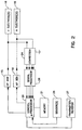
- FIG. 2 there is shown a block diagram of the primary components of an implantable pacemaker in accordance with this invention.
- a ventricular pulse generator shown at 15, delivers ventricular pacing pulses to one or more ventricular electrodes, illustrated at 16.
- stimulus pulses from generator 15 are delivered between tip electrode 16T and the pacemaker can; for bipolar pacing the pulses are delivered between electrodes 16T and 16R.
- control block 20 which suitably includes a microprocessor, which microprocessor in turn is operatively connected with memory 21.
- an atrial pulse generator 18 which would be included in a dual chamber DDD pacemaker, the pacing pulses from which are delivered to one or more atrial electrodes 19.
- a sensor or sensors 28 provide parameter signals which are connected to block 20 for providing rate responsive pacing, in a known manner.
- a transmitter/receiver 27 is in two-way communication with block 20, for receiving program instructions from an external programmer, and also for downloading collected data from the pacemaker to the programmer.
- the electrodes 16, 19 are shown connected to process block 26, which is described in greater detail in connection with Fig. 3.
- two ventricular electrodes may provide two signals conducted to connection block 24 on respective conductors within the ventricular lead, for a bipolar embodiment.
- signals sensed by atrial electrode 19, or electrodes 19, 19R are connected through to block 26.
- Ground is represented as also being connected to block 24, and in this case ground is suitably the pacemaker can, which acts as an indifferent electrode for unipolar sensing and/or pacing.
- the signals coming into block 24 are connected to control block 20, for processing and interpretation.
- processor 26 includes an amplifier(A) and a digital filter (DF) which filters and digitizes the signal for subsequent digital processing in control microprocessor block 20.
- V RING which is electrode 16R in Fig. 1
- V TIP electrode 16T
- a RING electrode 19 or 19R
- CAN which is part of housing 8 of the pacemaker.
- the processing channels in processor 26 are V RING - V TIP (V R/T); A RING - V TIP (R/T); V TIP - CAN (VT); and A RING - CAN (AR).
- processor 26 includes an amplifier(A) and a digital filter (DF) which filters and digitizes the signal for subsequent digital processing in control microprocessor block 20.
- DF digital filter
- any one or more of the output signals V R/T, RT, VT, and AR can be provided.
- the Enable signals are provided from control block 20.
- a second atrial ring may be used, providing for a bipolar AR-AR signal from electrodes 19, 19R.
- the last three of these signals are enabled and processed; the enable signals are programmable through transmitter/receiver 27.
- FIG. 4a there is shown a series of timing diagrams illustrating in stylized form the sensed AR, VT and RT signals.
- the AR signal between a floating atrial ring and can, provides a relatively large P-wave, and relatively small R-wave.
- the VT signal between the ventricular tip electrode and the can, shows a very small P-wave, and a relatively large negative going R-wave.
- the RT signal between the atrial ring and the ventricular tip, shows both a large negative going P-wave and a large positive going R-wave.
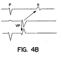
- FIG. 4b there are shown signals sensed in the AR, VT and RT channels when a ventricular pace pulse is delivered, showing the far field R wave as sensed in the AR channel.
- comparing the time of occurrence of signals on the AR, VT and RT channels leads to the following decisions which are carried out in control block 20: RT AR VT Decision - - 1 Undefined (noise or muscle potentials) - 1 - Undefined (noise or muscle potentials, FFRW) - 1 1 Undefined (noise or muscle potentials) 1 - - Undefined (noise or muscle potentials) 1 - 1 R-sense 1 1 - P-sense (or FFRW) 1 1 1 R-sense
- Fig. 5a there is shown a block diagram of steps taken by control block 20, in conjunction with memory, for serially processing of signals received concurrently by three or four channels, as indicated.
- the signals appearing on the various lines, or channels are digitally analyzed or compared for pattern recognition.
- each signal can be compared to one or more stored patterns representative of different types of cardiac signals; and/or the patterns can be compared to each other.
- the resulting pattern data is stored, and then the signals are compared at 34 in terms of timing sequence, as discussed in connection with Table I above.
- the signal is identified as a P-wave, an R-wave or an "other" type of wave.
- the result is stored in storage 37.
- a sense interpretation is made at 36, i.e., the P-wave or the R-wave is classified so as to enable the pacemaker logic to proceed with appropriate pacing therapy.
- Fig. 5b there is shown a block diagram of signal processing undertaken within the microprocessor for parallel processing of the concurrent channel information.
- the pattern recognition processing as shown at 32 and the timing processing as shown at 34 are done in parallel.
- the results of the pattern recognition and timing processing are weighted at 35, in accordance with predetermined weighting factors.
- sense interpretation is again made at 36, and data is stored at storage block 37.
Landscapes
- Health & Medical Sciences (AREA)
- Cardiology (AREA)
- Heart & Thoracic Surgery (AREA)
- Life Sciences & Earth Sciences (AREA)
- Biophysics (AREA)
- Physiology (AREA)
- Engineering & Computer Science (AREA)
- Biomedical Technology (AREA)
- Nuclear Medicine, Radiotherapy & Molecular Imaging (AREA)
- Radiology & Medical Imaging (AREA)
- Animal Behavior & Ethology (AREA)
- General Health & Medical Sciences (AREA)
- Public Health (AREA)
- Veterinary Medicine (AREA)
- Electrotherapy Devices (AREA)
Claims (9)
- Zweikammer-Herzschrittmachersystem für das Schrittsteuern des Herzens eines Patienten, mit:dadurch gekennzeichnet, dasseiner Impulseinrichtung (15, 18) zum Erzeugen von Schrittsteuerungsimpulsen,einer Einfachdurchgangsleitung (14) zur Abgabe von Schrittsteuerungsimpulsen an das Herz des Patienten und zum Erfassen von Herzsignalen vom Atrium und vom Ventrikel des Patienten, wobei die Leitung (14) mindestens eine auf ihr angeordnete Elektrode (19, 19R), die im Atrium platziert wird, und eine auf ihr angeordnete Elektrode (16T, 16R, 17), die im Ventrikel platziert wird, umfasst,einer neutralen Elektrode,einer Erfassungseinrichtung (24) zum Erfassen von Signalen zwischen entsprechenden Paaren der Atrioelektrode, der Ventrikelelektrode und der neutralen Elektrode,einer Freigabeeinrichtung (26) für die zyklische Freigabe eines oder mehrerer der Signale zur Verarbeitung, undeiner Verarbeitungseinrichtung (20) zum Verarbeiten der freigegebenen Signale, um auszuwerten, welche Art von Ereignis die erfassten Signale repräsentieren,die Freigabeeinrichtung eine programmierbare Einrichtung (26) für die zyklische Freigabe von mindestens zwei Signalen, die an zwei entsprechenden Elektrodenpaaren erfasst werden, umfasst.
- System nach Anspruch 1, dadurch gekennzeichnet, dass die Freigabeeinrichtung (26) eine Einrichtung für die Freigabe von drei entsprechenden erfassten Signalen zur Verarbeitung umfasst.
- System nach Anspruch 2, gekennzeichnet durch eine Dateneinrichtung (21) zum Akkumulieren von Daten, die sich auf die Auswertung von erfassten Signalen beziehen.
- System nach Anspruch 1, dadurch gekennzeichnet, dass das System einen implantierbaren Schrittmacher (6) umfasst, wobei der Schrittmacher ein Gehäuse (8) aufweist und die neutrale Elektrode ein Teil des Gehäuses (8) ist.
- System nach Anspruch 1, dadurch gekennzeichnet, dass die Verarbeitungseinrichtung (20) eine Digitalisiereinrichtung zum Digitalisieren der erfassten Signale hat.
- System nach Anspruch 1, dadurch gekennzeichnet, dass die Verarbeitungseinrichtung (20) eine Zeitsteuerungseinrichtung (34) zum Vergleichen der relativen Zeiten der mindestens zwei Signale und zum zyklischen Auswerten des von den mindestens zwei Signalen repräsentierten Ereignisses umfasst.
- System nach Anspruch 1, dadurch gekennzeichnet, dass die Einfachdurchgangsleitung (14) eine distale Punktelektrode (16T) und eine Ventrikel-Ringelektrode (16R) umfasst, die auf ihr angebracht sind und im Ventrikel platziert werden, wobei die Erfassungseinrichtung (24) eine bipolare Ventrikel-Einrichtung zum Erfassen von Signalen von der Punkt- und der Ventrikel-Ringelektrode hat.
- System nach Anspruch 1, dadurch gekennzeichnet, dass die Verarbeitungseinrichtung (20) eine Mustererkennungseinrichtung (32), die die Signale so verarbeitet, dass die Muster der Signale erkannt werden, eine Zeitsteuerungseinrichtung (34), die die Signale so verarbeitet, dass ihre relativen Zeiten verglichen werden, eine Schätzeinrichtung (35), die die Signifikanz der Mustererkennung und der relativen Zeiten abschätzt, um so abgeschätzte Daten zu erhalten, und eine Bewertungseinrichtung (36), die das durch die verarbeiteten Signale repräsentierte Ereignis gemäß den abgeschätzten Daten interpretiert, umfasst.
- System nach Anspruch 8, gekennzeichnet durch eine Speichereinrichtung (37) zum Speichern von Daten, die die abgeschätzten Daten und interpretierten Ereignisse repräsentieren.
Applications Claiming Priority (3)
| Application Number | Priority Date | Filing Date | Title |
|---|---|---|---|
| US09/032,977 US5999853A (en) | 1998-03-02 | 1998-03-02 | Dual chamber pacemaker with single pass lead and with bipolar and unipolar signal processing capability |
| PCT/EP1999/001335 WO1999044681A1 (en) | 1998-03-02 | 1999-03-02 | Dual chamber pacemaker with bipolar and unipolar signal processing |
| US32977 | 2005-01-11 |
Publications (2)
| Publication Number | Publication Date |
|---|---|
| EP1059962A1 EP1059962A1 (de) | 2000-12-20 |
| EP1059962B1 true EP1059962B1 (de) | 2005-10-12 |
Family
ID=21867891
Family Applications (1)
| Application Number | Title | Priority Date | Filing Date |
|---|---|---|---|
| EP99907581A Expired - Lifetime EP1059962B1 (de) | 1998-03-02 | 1999-03-02 | Zweikammer-herzschrittmacher mit signalverarbeitungsschaltung für bipolare und unipolare elektroden |
Country Status (4)
| Country | Link |
|---|---|
| US (1) | US5999853A (de) |
| EP (1) | EP1059962B1 (de) |
| DE (1) | DE69927675T2 (de) |
| WO (1) | WO1999044681A1 (de) |
Families Citing this family (36)
| Publication number | Priority date | Publication date | Assignee | Title |
|---|---|---|---|---|
| DE19800697B4 (de) * | 1998-01-10 | 2009-04-02 | Biotronik Gmbh & Co. Kg | Einzel-Elektrodensonde, insbesondere für implantierbare Defibrillatoren |
| EP1102560A4 (de) * | 1998-08-07 | 2003-03-12 | Infinite Biomedical Technologi | Technologie von implantierbaren vorrichtung zur detektion, anzeige und intervention bei myokardialer ischämie |
| US8527046B2 (en) | 2000-04-20 | 2013-09-03 | Medtronic, Inc. | MRI-compatible implantable device |
| US6925328B2 (en) | 2000-04-20 | 2005-08-02 | Biophan Technologies, Inc. | MRI-compatible implantable device |
| US7130682B2 (en) * | 2000-12-26 | 2006-10-31 | Cardiac Pacemakers, Inc. | Pacing and sensing vectors |
| US20020116028A1 (en) | 2001-02-20 | 2002-08-22 | Wilson Greatbatch | MRI-compatible pacemaker with pulse carrying photonic catheter providing VOO functionality |
| US6829509B1 (en) | 2001-02-20 | 2004-12-07 | Biophan Technologies, Inc. | Electromagnetic interference immune tissue invasive system |
| AU2002303502A1 (en) * | 2001-04-27 | 2002-11-11 | Quetzal Biomedical, Inc. | Improved leads for the treatment of patients with chf |
| US6654637B2 (en) | 2001-04-30 | 2003-11-25 | Medtronic, Inc. | Method and system for ventricular fusion prevention |
| US7054686B2 (en) | 2001-08-30 | 2006-05-30 | Biophan Technologies, Inc. | Pulsewidth electrical stimulation |
| US6731979B2 (en) | 2001-08-30 | 2004-05-04 | Biophan Technologies Inc. | Pulse width cardiac pacing apparatus |
| US6748268B1 (en) | 2001-08-31 | 2004-06-08 | Pacesetter, Inc. | Three lead universal pacing and shocking system |
| US6745081B1 (en) | 2001-08-31 | 2004-06-01 | Pacesetter, Inc. | Coronary Sinus Cardiac Lead For Stimulating and Sensing The Atria of the Right and Left Heart and System |
| US6760619B1 (en) | 2001-08-31 | 2004-07-06 | Pacesetter, Inc. | Two lead universal defibrillation, pacing and sensing system |
| US6721598B1 (en) | 2001-08-31 | 2004-04-13 | Pacesetter, Inc. | Coronary sinus cardiac lead for stimulating and sensing in the right and left heart and system |
| US6640136B1 (en) | 2001-09-12 | 2003-10-28 | Pacesetters, Inc. | Implantable cardiac stimulation device with automatic electrode selection for avoiding cross-chamber stimulation |
| US6988001B2 (en) | 2001-10-31 | 2006-01-17 | Biophan Technologies, Inc. | Hermetic component housing for photonic catheter |
| US7392085B2 (en) | 2001-11-21 | 2008-06-24 | Cameron Health, Inc. | Multiple electrode vectors for implantable cardiac treatment devices |
| US6968236B2 (en) | 2002-01-28 | 2005-11-22 | Biophan Technologies, Inc. | Ceramic cardiac electrodes |
| US6711440B2 (en) | 2002-04-11 | 2004-03-23 | Biophan Technologies, Inc. | MRI-compatible medical device with passive generation of optical sensing signals |
| US6725092B2 (en) | 2002-04-25 | 2004-04-20 | Biophan Technologies, Inc. | Electromagnetic radiation immune medical assist device adapter |
| US7110815B2 (en) | 2002-05-06 | 2006-09-19 | Cardiac Pacemakers, Inc. | System and method for providing temporary stimulation therapy to optimize chronic electrical performance for electrodes used in conjunction with a cardiac rhythm management system |
| US6925322B2 (en) | 2002-07-25 | 2005-08-02 | Biophan Technologies, Inc. | Optical MRI catheter system |
| US8825157B2 (en) | 2003-07-28 | 2014-09-02 | Cameron Health, Inc. | Vector switching in an implantable cardiac stimulus system |
| US7308307B1 (en) * | 2004-03-02 | 2007-12-11 | Pacesetter, Inc. | Implantable single-chamber atrial pacing device providing active ventricular far field sensing and rate limit |
| US7996083B2 (en) | 2004-06-02 | 2011-08-09 | Cardiac Pacemakers, Inc. | Far-field sensing channel for implantable cardiac device |
| US8200341B2 (en) | 2007-02-07 | 2012-06-12 | Cameron Health, Inc. | Sensing vector selection in a cardiac stimulus device with postural assessment |
| US8788023B2 (en) | 2006-05-26 | 2014-07-22 | Cameron Health, Inc. | Systems and methods for sensing vector selection in an implantable medical device |
| US7623909B2 (en) | 2006-05-26 | 2009-11-24 | Cameron Health, Inc. | Implantable medical devices and programmers adapted for sensing vector selection |
| US7783340B2 (en) * | 2007-01-16 | 2010-08-24 | Cameron Health, Inc. | Systems and methods for sensing vector selection in an implantable medical device using a polynomial approach |
| US8014851B2 (en) | 2006-09-26 | 2011-09-06 | Cameron Health, Inc. | Signal analysis in implantable cardiac treatment devices |
| US7738948B2 (en) * | 2006-10-31 | 2010-06-15 | Medtronic, Inc. | Form parameter forecaster for analyzing signals distorted by noise |
| US8067917B2 (en) * | 2008-04-08 | 2011-11-29 | Liebert Corporation | Hysteresis mitigation and control method |
| US20100137927A1 (en) * | 2008-12-01 | 2010-06-03 | Tengiz Tkebuchava | Multifunctional cardiac pacemaker system |
| WO2013069003A1 (en) | 2011-11-11 | 2013-05-16 | National University Of Ireland, Galway | Muscle stimulation device |
| US9579065B2 (en) | 2013-03-12 | 2017-02-28 | Cameron Health Inc. | Cardiac signal vector selection with monophasic and biphasic shape consideration |
Citations (1)
| Publication number | Priority date | Publication date | Assignee | Title |
|---|---|---|---|---|
| US5423873A (en) * | 1992-09-02 | 1995-06-13 | Siemens Elema Ab | Device for stimulating living tissue |
Family Cites Families (16)
| Publication number | Priority date | Publication date | Assignee | Title |
|---|---|---|---|---|
| US4549548A (en) * | 1983-09-14 | 1985-10-29 | Vitafin N.V. | Pacemaker system with automatic event-programmed switching between unipolar and bipolar operation |
| US4799486A (en) * | 1987-03-13 | 1989-01-24 | Cardiac Pacemakers, Inc. | Refractoriless atrial sensing in dual chamber pacemakers |
| US5222493A (en) * | 1990-10-01 | 1993-06-29 | Siemens Pacesetter, Inc. | Verification of capture using an indifferent electrode mounted on the pacemaker connector top |
| US5193550A (en) * | 1990-11-30 | 1993-03-16 | Medtronic, Inc. | Method and apparatus for discriminating among normal and pathological tachyarrhythmias |
| US5172694A (en) * | 1991-05-30 | 1992-12-22 | Vitatron Medical B.V. | Single pacing lead and method utilizing two different floating bipoles |
| US5312445A (en) * | 1992-02-03 | 1994-05-17 | Telectronics Pacing Systems, Inc. | Implantable cardiac stimulating apparatus and method employing detection of P-waves from signals sensed in the ventricle |
| US5265601A (en) * | 1992-05-01 | 1993-11-30 | Medtronic, Inc. | Dual chamber cardiac pacing from a single electrode |
| US5324310A (en) * | 1992-07-01 | 1994-06-28 | Medtronic, Inc. | Cardiac pacemaker with auto-capture function |
| SE9203284D0 (sv) * | 1992-11-04 | 1992-11-04 | Siemens Elema Ab | Hjaertstimulator |
| US5330512A (en) * | 1992-12-28 | 1994-07-19 | Cardiac Pacemakers, Inc. | Electrode charge-neutral sensing of evoked ECG |
| US5385146A (en) * | 1993-01-08 | 1995-01-31 | Goldreyer; Bruce N. | Orthogonal sensing for use in clinical electrophysiology |
| US5387233A (en) * | 1993-01-11 | 1995-02-07 | Incontrol, Inc. | Intravenous cardiac lead with improved fixation and method |
| SE9303121D0 (sv) * | 1993-09-24 | 1993-09-24 | Siemens Elema Ab | Hjärtstimulator |
| US5674274A (en) * | 1995-12-14 | 1997-10-07 | Pacesetter, Inc. | Implantable adjustable single-pass A-V lead for use with an implantable stimulation device |
| US5800465A (en) * | 1996-06-18 | 1998-09-01 | Medtronic, Inc. | System and method for multisite steering of cardiac stimuli |
| US5755738A (en) * | 1997-04-22 | 1998-05-26 | Cardiac Pacemakers, Inc. | Automatic sensing level adjustment for implantable cardiac rhythm management devices |
-
1998
- 1998-03-02 US US09/032,977 patent/US5999853A/en not_active Expired - Lifetime
-
1999
- 1999-03-02 DE DE69927675T patent/DE69927675T2/de not_active Expired - Lifetime
- 1999-03-02 WO PCT/EP1999/001335 patent/WO1999044681A1/en not_active Ceased
- 1999-03-02 EP EP99907581A patent/EP1059962B1/de not_active Expired - Lifetime
Patent Citations (1)
| Publication number | Priority date | Publication date | Assignee | Title |
|---|---|---|---|---|
| US5423873A (en) * | 1992-09-02 | 1995-06-13 | Siemens Elema Ab | Device for stimulating living tissue |
Also Published As
| Publication number | Publication date |
|---|---|
| WO1999044681A1 (en) | 1999-09-10 |
| US5999853A (en) | 1999-12-07 |
| DE69927675T2 (de) | 2006-07-06 |
| DE69927675D1 (de) | 2005-11-17 |
| EP1059962A1 (de) | 2000-12-20 |
Similar Documents
| Publication | Publication Date | Title |
|---|---|---|
| US5999853A (en) | Dual chamber pacemaker with single pass lead and with bipolar and unipolar signal processing capability | |
| US9427594B1 (en) | Method and system for tracking events of interest between leadless and subcutaneous implantable cardioverter devices | |
| US6745076B2 (en) | Implantable medical device with autosensitivity algorithm for controlling sensing of cardiac signals | |
| US6934585B1 (en) | System and method for far-field R-wave detection | |
| US8140156B2 (en) | Heart sound sensing to reduce inappropriate tachyarrhythmia therapy | |
| EP1735049B1 (de) | Echtzeit-optimierung der rechts/linksventrikulären zeitsequenz bei biventrikulärem pacing bei patienten mit herzinsuffizienz | |
| EP1430931B1 (de) | Herzschrittmacher | |
| US6334071B1 (en) | Minute volume pacemakers that require only a single distal electrode | |
| US4712555A (en) | Physiologically responsive pacemaker and method of adjusting the pacing interval thereof | |
| US6760622B2 (en) | Implantable multi-chamber cardiac stimulation device with sensing vectors | |
| EP1123716B1 (de) | Verfahren zur Unterscheidung von im Herzen erfassten elektrischen Ereignissen und entsprechendes System | |
| US8224445B2 (en) | Far-field sensing channel for implantable cardiac device | |
| US8280500B2 (en) | Discrimination of ventricular tachycardia from supraventricular tachycardia | |
| EP0220194B1 (de) | Messung des herzschlagintervalls eines stimulierten herzes, sich anpassender herzschrittmacher und betriebsart | |
| US7873410B2 (en) | Implantable medical device with electromechanical delay measurement for lead position and ventricular | |
| US6901291B2 (en) | Distinguishing valid and invalid cardiac senses | |
| EP1499385B1 (de) | Ventrikuläre sicherheitsreizung in biventrikulärer herzreizung | |
| US6754529B2 (en) | Committed ventricular safety pacing | |
| US7873414B2 (en) | Patient characteristic based adaptive anti-tachy pacing programming | |
| US7184816B2 (en) | Cardiac stimulating and detecting device, system and method for identifying far field signals | |
| US7599739B2 (en) | Multi-chamber timing for premature cardiac pacing | |
| EP1954349A1 (de) | Implantierbare herzstimulationsvorrichtung und verfahren |
Legal Events
| Date | Code | Title | Description |
|---|---|---|---|
| PUAI | Public reference made under article 153(3) epc to a published international application that has entered the european phase |
Free format text: ORIGINAL CODE: 0009012 |
|
| 17P | Request for examination filed |
Effective date: 20000912 |
|
| AK | Designated contracting states |
Kind code of ref document: A1 Designated state(s): CH DE FR LI NL SE |
|
| RIN1 | Information on inventor provided before grant (corrected) |
Inventor name: WESTENDORP, HENDRIKUS, A. Inventor name: WOHLGEMUTH, WERNER, P. Inventor name: STOOP, GUSTAAF, A., P. |
|
| 17Q | First examination report despatched |
Effective date: 20040202 |
|
| GRAP | Despatch of communication of intention to grant a patent |
Free format text: ORIGINAL CODE: EPIDOSNIGR1 |
|
| GRAS | Grant fee paid |
Free format text: ORIGINAL CODE: EPIDOSNIGR3 |
|
| GRAA | (expected) grant |
Free format text: ORIGINAL CODE: 0009210 |
|
| AK | Designated contracting states |
Kind code of ref document: B1 Designated state(s): CH DE FR LI NL SE |
|
| REG | Reference to a national code |
Ref country code: CH Ref legal event code: EP |
|
| REF | Corresponds to: |
Ref document number: 69927675 Country of ref document: DE Date of ref document: 20051117 Kind code of ref document: P |
|
| REG | Reference to a national code |
Ref country code: SE Ref legal event code: TRGR |
|
| REG | Reference to a national code |
Ref country code: CH Ref legal event code: NV Representative=s name: ISLER & PEDRAZZINI AG |
|
| ET | Fr: translation filed | ||
| PLBE | No opposition filed within time limit |
Free format text: ORIGINAL CODE: 0009261 |
|
| STAA | Information on the status of an ep patent application or granted ep patent |
Free format text: STATUS: NO OPPOSITION FILED WITHIN TIME LIMIT |
|
| 26N | No opposition filed |
Effective date: 20060713 |
|
| PGFP | Annual fee paid to national office [announced via postgrant information from national office to epo] |
Ref country code: CH Payment date: 20070110 Year of fee payment: 9 |
|
| PGFP | Annual fee paid to national office [announced via postgrant information from national office to epo] |
Ref country code: NL Payment date: 20070214 Year of fee payment: 9 |
|
| PGFP | Annual fee paid to national office [announced via postgrant information from national office to epo] |
Ref country code: SE Payment date: 20070305 Year of fee payment: 9 |
|
| REG | Reference to a national code |
Ref country code: CH Ref legal event code: PCAR Free format text: ISLER & PEDRAZZINI AG;POSTFACH 1772;8027 ZUERICH (CH) |
|
| REG | Reference to a national code |
Ref country code: CH Ref legal event code: PL |
|
| EUG | Se: european patent has lapsed | ||
| PG25 | Lapsed in a contracting state [announced via postgrant information from national office to epo] |
Ref country code: NL Free format text: LAPSE BECAUSE OF NON-PAYMENT OF DUE FEES Effective date: 20081001 |
|
| NLV4 | Nl: lapsed or anulled due to non-payment of the annual fee |
Effective date: 20081001 |
|
| PG25 | Lapsed in a contracting state [announced via postgrant information from national office to epo] |
Ref country code: SE Free format text: LAPSE BECAUSE OF NON-PAYMENT OF DUE FEES Effective date: 20080303 Ref country code: LI Free format text: LAPSE BECAUSE OF NON-PAYMENT OF DUE FEES Effective date: 20080331 Ref country code: CH Free format text: LAPSE BECAUSE OF NON-PAYMENT OF DUE FEES Effective date: 20080331 |
|
| PGFP | Annual fee paid to national office [announced via postgrant information from national office to epo] |
Ref country code: FR Payment date: 20140317 Year of fee payment: 16 |
|
| REG | Reference to a national code |
Ref country code: FR Ref legal event code: ST Effective date: 20151130 |
|
| PG25 | Lapsed in a contracting state [announced via postgrant information from national office to epo] |
Ref country code: FR Free format text: LAPSE BECAUSE OF NON-PAYMENT OF DUE FEES Effective date: 20150331 |
|
| PGFP | Annual fee paid to national office [announced via postgrant information from national office to epo] |
Ref country code: DE Payment date: 20160331 Year of fee payment: 18 |
|
| REG | Reference to a national code |
Ref country code: DE Ref legal event code: R119 Ref document number: 69927675 Country of ref document: DE |
|
| PG25 | Lapsed in a contracting state [announced via postgrant information from national office to epo] |
Ref country code: DE Free format text: LAPSE BECAUSE OF NON-PAYMENT OF DUE FEES Effective date: 20171003 |