EP1060573B1 - Verfahren und gerät zur spektralumformung in einem transformationskodierer für hochwertige tonsignale - Google Patents
Verfahren und gerät zur spektralumformung in einem transformationskodierer für hochwertige tonsignale Download PDFInfo
- Publication number
- EP1060573B1 EP1060573B1 EP98904515A EP98904515A EP1060573B1 EP 1060573 B1 EP1060573 B1 EP 1060573B1 EP 98904515 A EP98904515 A EP 98904515A EP 98904515 A EP98904515 A EP 98904515A EP 1060573 B1 EP1060573 B1 EP 1060573B1
- Authority
- EP
- European Patent Office
- Prior art keywords
- exponent
- coded
- sequence
- differential
- coefficient
- Prior art date
- Legal status (The legal status is an assumption and is not a legal conclusion. Google has not performed a legal analysis and makes no representation as to the accuracy of the status listed.)
- Expired - Lifetime
Links
- 238000000034 method Methods 0.000 title claims description 43
- 230000003595 spectral effect Effects 0.000 title description 29
- 230000006835 compression Effects 0.000 description 9
- 238000007906 compression Methods 0.000 description 9
- 238000001228 spectrum Methods 0.000 description 9
- 230000005236 sound signal Effects 0.000 description 6
- 238000010586 diagram Methods 0.000 description 3
- 230000006698 induction Effects 0.000 description 3
- 230000001939 inductive effect Effects 0.000 description 2
- 230000000873 masking effect Effects 0.000 description 2
- 238000013139 quantization Methods 0.000 description 2
- 230000015556 catabolic process Effects 0.000 description 1
- 238000006731 degradation reaction Methods 0.000 description 1
- 230000000694 effects Effects 0.000 description 1
- 238000005516 engineering process Methods 0.000 description 1
- 238000000605 extraction Methods 0.000 description 1
- 238000013507 mapping Methods 0.000 description 1
- 238000010606 normalization Methods 0.000 description 1
Images



Classifications
-
- H—ELECTRICITY
- H03—ELECTRONIC CIRCUITRY
- H03M—CODING; DECODING; CODE CONVERSION IN GENERAL
- H03M7/00—Conversion of a code where information is represented by a given sequence or number of digits to a code where the same, similar or subset of information is represented by a different sequence or number of digits
- H03M7/30—Compression; Expansion; Suppression of unnecessary data, e.g. redundancy reduction
- H03M7/3002—Conversion to or from differential modulation
-
- H—ELECTRICITY
- H04—ELECTRIC COMMUNICATION TECHNIQUE
- H04B—TRANSMISSION
- H04B1/00—Details of transmission systems, not covered by a single one of groups H04B3/00 - H04B13/00; Details of transmission systems not characterised by the medium used for transmission
- H04B1/66—Details of transmission systems, not covered by a single one of groups H04B3/00 - H04B13/00; Details of transmission systems not characterised by the medium used for transmission for reducing bandwidth of signals; for improving efficiency of transmission
- H04B1/665—Details of transmission systems, not covered by a single one of groups H04B3/00 - H04B13/00; Details of transmission systems not characterised by the medium used for transmission for reducing bandwidth of signals; for improving efficiency of transmission using psychoacoustic properties of the ear, e.g. masking effect
Definitions
- This invention is applicable in the field of audio coders, which employ differential coding of the exponents obtained by normalisation of the frequency domain coefficients.
- the amount of information required to represent the audio signals may be reduced.
- the amount of digital information needed to accurately reproduce the original pulse code modulation (PCM) samples may be reduced by applying a digital compression algorithm, resulting in a digitally compressed representation of the original signal.
- the goal of the digital compression algorithm is to produce a digital representation of an audio signal which, when decoded and reproduced, sounds the same as the original signal, while using a minimum of digital information for the compressed or encoded representation.
- the time domain audio signal is first converted to the frequency domain using a bank of filters.
- the frequency domain coefficients, thus generated, are converted to fixed point representation.
- each coefficient is represented as a mantissa and an exponent.
- the bulk of the compressed bitstream transmitted to the decoder comprises these exponents and mantissas.
- each mantissa must be truncated to a fixed or variable number of decimal places.
- the number of bits to be used for coding each mantissa is obtained from a bit allocation algorithm which may be based on the masking property of the human auditory system. Lower numbers of bits result in higher compression ratios because less space is required to transmit the coefficients. However, this may cause high quantization errors, leading to audible distortion.
- a good distribution of available bits to each mantissa forms the core of the advanced audio coders.
- differential coding for the exponents.
- the exponents for a channel are differentially coded across the frequency range.
- the first exponent is sent as an absolute value.
- Subsequent exponent information is sent in differential form, subject to a maximum limit. That is, consecutive exponents are allowed to differ only within a given upper limit. This restriction is called the differential-constrain, the impact of which is addressed herein.
- the differential coding of exponents with a limit on maximum allowable difference between any two consecutive exponents may result in signal distortion.
- the differential-constraint may force some exponents to be coded to a value larger than the original, while others may be restricted to smaller value than the original.
- a method for coding a sequence of frequency coefficients comprising respective exponents and mantissas in a digital audio coder comprising:
- the first predetermined condition preferably corresponds to an information loss as a result of said differential constraint limit.
- differentially coding said frequency coefficients includes shifting the coded mantissa of a coefficient to prevent information loss in the coded coefficient as a result of application of the differential constraint limit to the corresponding coded efficient exponent.
- the present invention also provides a method for coding a sequence of data elements each comprising an exponent and corresponding mantissa, including the steps of:
- sequence of data elements comprise data representing digital audio data frequency coefficients.
- step e)ii) is carried out until the differences in value between adjacent coded exponents of each of the data elements from the local peak to the first data element are within said differential limit.
- the successive data element coded at step b) is the data element sequentially following said local peak data element.
- the present invention further provides a digital audio coder for generating coded frequency coefficients from digital audio data, comprising:
- the differential coding processor shifts the coded mantissa of a coefficient to prevent information loss in the coded coefficient as a result of application of the differential constraint limit to the corresponding coded coefficient exponent.
- the input to an audio coder comprises a stream of digitised samples of the time domain analog audio signal.
- the input stream is sectioned into blocks, each block containing n consecutive samples.
- the n samples form an ordered set ( s 0 , s 1 , s 2 , ..., s n-1 ).
- the time domain samples ( s 0 , s 1 , s 2 , ..., s n-1 ) are converted to the frequency domain using an analysis filter bank (see Fig. 1)
- the frequency domain coefficients, thus generated, form another ordered set which can be identified as ( c 0 , c 1 , c 2 , ..., c n-1 ).
- c 0 is the lowest frequency (DC) component
- c n-1 is the highest frequency component of the signal.
- audio compression entails finding how much of the information in the set ( c 0 , c 1 , c 2 , ..., c n-1 ) is necessary to reproduce the original analog signal at the decoder with minimal audible distortion.
- each coefficient c i is represented by an exponent e and mantissa m .
- e floor(log 2 (c i )) . Since coefficients are always less than unity, the exponent is always non-positive.
- mantissa m i (c i ) / e i .
- the exponents and mantissas form two ordered sets ( e 0 , e 1 , e 2 , ..., e n-1 ) and ( m 0 , m 1 , m 2 , ..., m n-1 ).
- the exponent set is usually transmitted in its original form.
- the mantissa is truncated to a fixed or variable number of decimal places.
- each mantissa m i is transmitted as b i number of bits.
- the value of b i is usually obtained from a bit allocation algorithm which for advanced psychoacoustic coders may be based on the masking property of the human auditory system. Low values of b i result in higher compression ratios because less space is required to transmit the coefficients. However this causes very high quantization error, leading to audible distortion.
- a good distribution of available bits to each mantissa forms the core of the most advanced encoders.
- differential coding for the exponent set.
- the exponents for a channel are differentially coded across frequency range.
- the first component c 0 is sent as an absolute value.
- Subsequent coefficient information is sent in differential form, subject to a differential limit, L.
- each differential exponent instead of sending the value of e i the value ( e i - e i-1 ) is sent, subject to a maximum of +/- L. That is a difference of up to +/-L is only allowed between two consecutive exponents. This restriction is called the differential constraint, the impact of which is discussed below.
- the exponent set (e 0 , e 1 , e 2 , ..., e n-1 ) generated for a particular case is as follows: e 0 e 1 e 2 e 3 e 4 e 5 e 6 e 7 e 8 e 9 e 10 e 11 e 12 e 13 e 14 e 15 e 16 -13 -16 -12 -13 -12 -9 0 -10 -18 -20 -19 -5 -19 -21 -22 -20 -22 -22 -22 -22 -22 -22 -22 -22 .
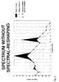
- Figure 3 shows the deviation of differentially encoded spectral envelope from the original spectrum due to the differential-constraint.
- the shaded region corresponds to the error due to differential coding, as explained in the analysis below.
- exponent can be sent as -3, as per the constraint.
- the mantissa is however adjusted to 00 m i0 m i1 m i2 m i3 ...
- exponent can be sent as -6, as per the constraint.
- the mantissa is always treated as normalised (0. m i0 m i1 m i2 m i3 ..).
- e i-1 has been recoded successfully as e' i-1 without loss of information. Due to the differential-constraint, suppose e i can be represented closest as e' i (closest in the sense that ⁇ e i - e' i ⁇ is minimum). If i e' i ⁇ e then according to the above theorem, there is no information loss because the mantissa can be readjusted. Having coded e i as e' i the algorithm moves forward to code e i+1 . However, if e' i ⁇ e i then information loss will occur and one more step of processing must be performed.
- the algorithm continues the conventional exponent coding on the right of e i+p until it reaches another point where information loss due to differential-constraint occurs again. Because after every spectral reshaping to the left of e i+p the algorithm moves on to process the element e i+p+1 , and the number of elements in the set are finite, the algorithm is certain to terminate finally when the end of the ordered set is reached.
- an order analysis can be used to show that even in the worst case the algorithm takes O(n) time.
- the initial exponent set be ( e 0 , e 1 , e 2 , e 3 , ..., e n-1 ).
- each comparison or re-coding takes 0(1) time.
- the number of bits are fixed, therefore the exponents are restricted to be more than a minima.
- the minima is ⁇ .
- the worst case for the algorithm is when the input exponent set is ( ⁇ , ⁇ , ⁇ , ... ⁇ ) and the final optimally reshaped exponent set is (0,0,0 ..., 0) .
- the worst case scenario since the worst case scenario is considered, an element is incremented by only one unit. Therefore there are, in the worst case, K 1 ⁇ n comparisons and K 2 ⁇ n re-codings (K 1 and K 2 are arbitrary constants). Therefore the algorithm, even in the worst case, gives O(n) performance. Moreover, any operation on all n numbers cannot be done in less than O(n) time, therefore no other algorithm can give a better order performance.
- the finally coded exponents are: e ' 0 e' 1 e' 2 e' 3 e' 4 e' 5 e' 6 e' 7 e' 8 e' 9 e' 10 e' 11 e' 12 e' 13 e' 14 e' 15 e' 16 -12 -10 -8 -6 -4 -2 0 -2 -4 -6 -7 -5 -7 -9 -11 -13 -15
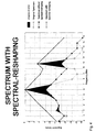
- Figure 4 is a graph illustrating a comparison between the original spectrum, the coded spectrum limited by the differential constraint, and the exponent set after spectral reshaping.
- a flow-chart diagram illustrating a procedure 50 for efficient differential coding of frequency domain coefficients in exponent and mantissa form without significant information loss is shown in Figure 5.
- a set of coefficients is received, comprising an ordered set of exponents (e 0 , e 1 , e 2 , ..., e 11-1 ) and mantissas (m 0 , m 1 , m 2 , ... , m n-1 ).
- the procedure then initialises an index i, and determines the differential constraint limit L (step 54).
- the differential constraint limit is the limit by which adjacent coded exponents for the ordered exponent set may differ from one another following the differential coding.
- the first exponent in the set (e 0 ) is coded as a base value (step 56), together with the corresponding mantissa m 0 .
- the index i is then incremented and the next exponent e 1 is selected from input data set (step 58).
- the absolute difference between the selected exponent value (e i ) and the preceding exponent value i-1 (e ) is then compared with the differential constraint limit (L) to determine whether the differential constraint applies (step 60).
- the exponent e i can be differentially coded according to its original value (at least for the time being) without application of the differential constraint, and in that case the procedure passes to step 62 to generate the coded exponent (e' i ) before returning to step 58.
- step 64 the constrained coded version of the exponent is calculated (e' i ).
- the constrained coded exponent is then compared with the original exponent to determine whether the application of the differential constraint will result in a loss of information. If the coded exponent is less than the original exponent value then information loss can be avoided by shifting the corresponding mantissa bits, and in that case the procedure passes to step 68 for manipulation of the mantissa m 1 . This manipulation is performed by shifting of the mantissa bits to the right (towards the least-significant-bit) by a number of positions corresponding to the integer difference between the coded and original exponent values.
- the procedure then carries on to step 62 where the exponent is coded according to the differential limit, before returning to step 58.
- the procedure then carries out the re-coding (or "spectral reshaping") of exponents to the "left" of the local maximum (i.e. for exponents with index values less than that of the local maximum (j)). This is performed by a looped routine involving steps 76 to 84 of the procedure 50. At step 76 the index counter j is decremented to select the next exponent "down" from the local maximum. The selected exponent e j is then coded (step 78) as e' j , constrained by the differential limit with respect to e' j+1 .
- the mantissa is manipulated at step 80 to generate the coded mantissa m' j .
- Steps 82 and 84 are provided to determine when the spectral reshaping can be terminated and the procedure return to normal differential coding.
- the procedure first determines whether the sequence position (j) of the re-coding process has yet reached the original index position (i). If not, the re-coding process loops back to step 76 to select the next exponent for re-coding. If the re-coding process has reached the starting index (i) then the absolute difference between the re-coded exponent and the next lowest index exponent as originally coded is compared with the differential constraint limit L (step 84). If the difference exceeds the limit, the re-coding process continues by looping back to step 76.
- the spectral reshaping can stop and the procedure return to normal differential coding. This is accomplished by setting the current coding index i to the local maximum stored by index k (step 86) and returning to step 58.
- the audio data coder apparatus 10 for carrying out the above described method is illustrated in Figure 1.
- a frequency transform processor in the form of an analysis filter bank 12 is coupled to receive the input audio data stream s 0 , s 1 , ... , s n-1 .
- the filter bank generates frequency coefficients c 0 , c 1 , ... , c n-1 , which are passed to a differential coding processor 14.
- the differential coding processor 14 comprises an exponent extraction processor 16 which arranges the coefficients in a fixed point representation comprising exponents and mantissas, and passes the exponents and mantissas to a spectral exponent reshaping processor 18.
- the processor 18 codes the exponents and mantissas as above described, and outputs the coded coefficients for inclusion in the output (e.g. AC-3 format) data stream.
- e i-1 has been recorded successfully as e' i-1 without loss of information. Due to the differential-constraint, suppose e i can be represented closest as e' i (closest in the sense that ⁇ e i - e' i ⁇ is minimum). If e' i ⁇ e i then according to the theorem, there is no information loss. Having coded e i as e' i , the algorithm moves forward to code e i+1 . However, if e i i ⁇ e i then information loss will occur and one more step of processing must be performed.
- the algorithm continues the conventional exponent coding on the right of e i+1 till it reaches another point where information loss due to differential-constraint occurs again.
Landscapes
- Engineering & Computer Science (AREA)
- Theoretical Computer Science (AREA)
- Computer Networks & Wireless Communication (AREA)
- Signal Processing (AREA)
- Compression, Expansion, Code Conversion, And Decoders (AREA)
Claims (10)
- Verfahren zum Codieren einer Sequenz von Datenelementen, die jeweils einen Exponenten und eine entsprechende Mantisse aufweisen, aufweisend die Schritte:a) Codieren (56) eines ersten Datenelements in der Sequenz als Basiswert;b) Codieren (64) eines nachfolgenden Datenelements in der Sequenz mit einem codierten Exponenten, der durch eine differenzielle Grenze begrenzt ist in Bezug auf den vorausgehenden Datenelementexponenten;c) Ermitteln (66) einer Differenz zwischen den codierten Exponenten des nachfolgenden Datenelements und seines originalen Exponenten als Ergebnis der differenziellen Grenze;d) Falls die im Schritt c) ermittelte Differenz ein erstes Vorzeichen aufweist, Verschieben (68) der codierten Mantisse des nachfolgenden Datenelements in Übereinstimmung mit dem Ausmaß der Differenz;
gekennzeichnet durch die Schritte:e) Falls die im Schritt c) ermittelte Differenz ein zweites Vorzeichen aufweist:i) Prüfen (70) der Datenelemente in der Sequenz zum Identifizieren eines Datenelementexponenten in einem nachfolgenden lokalen Spitzenwert in Exponentenwerten;ii) Codieren (78, 80) von Datenelementen in umgekehrter Sequenzabfolge ausgehend von dem lokalen Spitzenwertdatenelement mit codierten Exponenten, die durch die Differenzialgrenze beschränkt sind und entsprechenden Mantissen, die in Übereinstimmung mit einer Differenz zwischen den jeweiligen codierten und originalen Exponentenwerten verschoben sind; undf) Wiederholen der Schritte b) bis e) für die Datenelemente in der Sequenz. - Verfahren nach Anspruch 1, wobei die Sequenz von Datenelementen Daten aufweist, die digitale Audiodatenfrequenzkoeffizienten darstellen.
- Verfahren nach Anspruch 1, wobei das umgekehrte Codieren (78, 80) gemäß Schritt e)ii) ausgeführt wird, bis die Wertdifferenzen zwischen benachbarten codierten Exponenten von jedem der Datenelemente ausgehend vom lokalen Spitzenwert bis zum ersten Datenelement innerhalb der differenziellen Grenze liegen.
- Verfahren nach Anspruch 1, 2 oder 3, wobei folgend auf die Ausführung des Schritts e) das im Schritt b) codierte nachfolgende Datenelement dasjenige Datenelement ist, das sequenziell auf das lokale Spitzenwertdatenelement folgt.
- Verfahren zum Codieren einer Sequenz von Frequenzkoeffizienten, aufweisend jeweilige Exponenten und Mantissen in einem digitalen Audiocodierer, aufweisend:a) Wählen (56) eines Basisfrequenzkoeffizienten in der Sequenz;b) Differenzielles Codieren (62, 68) der Frequenzkoeffizienten mit einer vorab gewählten differenziellen Abhängigkeitsgrenze ausgehend von dem Basiskoeffizienten in einer Sequenzvorwärtsrichtung, bis eine erste vorbestimmte Bedingung in Bezug auf Exponentenwerte benachbarter Frequenzkoeffizienten in der Sequenz ermittelt wird; gekennzeichnet durch die Schritte:c) Identifizieren (70) eines lokalen Spitzenwerts in Exponentenwerten von Koeffizienten in der Sequenzvorwärtsrichtung und Wählen des Spitzenwertkoeffizienten als neuen Basisfrequenzkoeffizienten;d) Differenzielles Codieren (78, 80) der Frequenzkoeffizienten mit der differenziellen Abhängigkeitsgrenze ausgehend von dem Basiskoeffizienten in einer umgekehrten Sequenzrichtung, bis eine zweite vorbestimmte Bedingung in Bezug auf Exponentenwerte benachbarter Frequenzkoeffizienten in der Sequenz ermittelt wird; unde) Wiederholen ausgehend vom Schritt b), bis die gesamte Sequenz von Frequenzkoeffizienten codiert worden ist.
- Verfahren nach Anspruch 5, wobei die erste vorbestimmte Bedingung einem Informationsverlust infolge der differenziellen Abhängigkeitsgrenze entspricht.
- Verfahren nach Anspruch 5, wobei das differenzielle Codieren (62, 68) der Frequenzkoeffizienten das Verschieben (68, 80) der codierten Mantisse eines Koeffizienten umfasst, um Informationsverlust in dem codierten Koeffizienten infolge der Anwendung der differenziellen Abhängigkeitsgrenze auf den entsprechenden codierten Koeffizientenexponenten zu verhindern.
- Digitale Audiocodierer zum Erzeugen codierter Frequenzkoeffizienten für digitale Audiodaten, aufweisend:Einen Frequenzdomänentransformationsprozessor (12), der in Verbindung steht, um Eingangsaudiodaten zu empfangen und eine Sequenz von Frequenzkoeffizienten daraus zu erzeugen, wobei jeder Frequenzkoeffizient einen Exponenten und eine Mantisse aufweist;einen Difrerenzialcodierungsprozessor (16), der in Verbindung gebracht ist, um die Sequenz von Frequenzkoeffizienten von dem Frequenzdomänentransformationsprozessor zu empfangen, und der dazu ausgelegt ist, einen Basisfrequenzkoeffizienten von der Sequenz zu wählen, und dazu, iterativ Folgendes auszuführen:dadurch gekennzeichnet, dass der Differenzialcodierungsprozessor (16) außerdem ausgelegt ist für Folgendes:Differenzielles Codieren (62, 68) der Frequenzkoeffizienten mit einer vorab gewählten differenziellen Abhängigkeitsgrenze von dem Basiskoeffizienten in einer Sequenzvorwärtsrichtung, bis eine erste vorbestimmte Bedingung in Bezug auf Exponentenwerte benachbarter Frequenzkoeffizienten in der Sequenz ermittelt wird;Identifizieren (70) eines lokalen Spitzenwerts in Exponentenwerten von Koeffizienten in der Sequenzvorwärtsrichtung und Wählen des Spitzenwertkoeffizienten als neuen Basisfrequenzkoeffizienten, undDifferenzielles Codieren (78, 80) der Frequenzkoeffizienten mit der differenziellen Abhängigkeitsgrenze ausgehend von dem Basiskoeffizienten in umgekehrter Sequenzrichtung, bis eine zweite vorbestimmte Bedingung in Bezug auf Exponentenwerte benachbarter Frequenzkoeffizienten in der Sequenz ermittelt wird;bis die gesamte Sequenz von Frequenzkoeffizienten codiert worden ist.
- Vorrichtung nach Anspruch 8, wobei die erste vorbestimmte Bedingung einen Informationsverlust infolge der differenziellen Abhängigkeitsgrenze entspricht.
- Vorrichtung nach Anspruch 8, wobei der Differenzialcodierungsprozessor (16) die codierte Mantisse eines Koeffizienten verschiebt, um Informationsverlust in dem codierten Koeffizienten infolge des Zutreffens bzw. der Anwendung der differenziellen Abhängigkeitsgrenze auf den entsprechenden codierten Koeffizientenexponenten zu verhindern.
Applications Claiming Priority (1)
| Application Number | Priority Date | Filing Date | Title |
|---|---|---|---|
| PCT/SG1998/000002 WO1999035758A1 (en) | 1998-01-12 | 1998-01-12 | Method and apparatus for spectral exponent reshaping in a transform coder for high quality audio |
Publications (2)
| Publication Number | Publication Date |
|---|---|
| EP1060573A1 EP1060573A1 (de) | 2000-12-20 |
| EP1060573B1 true EP1060573B1 (de) | 2002-09-18 |
Family
ID=20429826
Family Applications (1)
| Application Number | Title | Priority Date | Filing Date |
|---|---|---|---|
| EP98904515A Expired - Lifetime EP1060573B1 (de) | 1998-01-12 | 1998-01-12 | Verfahren und gerät zur spektralumformung in einem transformationskodierer für hochwertige tonsignale |
Country Status (4)
| Country | Link |
|---|---|
| US (1) | US6839674B1 (de) |
| EP (1) | EP1060573B1 (de) |
| DE (1) | DE69808146T2 (de) |
| WO (1) | WO1999035758A1 (de) |
Families Citing this family (6)
| Publication number | Priority date | Publication date | Assignee | Title |
|---|---|---|---|---|
| DE69813912T2 (de) | 1998-10-26 | 2004-05-06 | Stmicroelectronics Asia Pacific Pte Ltd. | Digitaler audiokodierer mit verschiedenen genauigkeiten |
| WO2001033718A1 (en) * | 1999-10-30 | 2001-05-10 | Stmicroelectronics Asia Pacific Pte Ltd. | A method of encoding frequency coefficients in an ac-3 encoder |
| US7460684B2 (en) | 2003-06-13 | 2008-12-02 | Nielsen Media Research, Inc. | Method and apparatus for embedding watermarks |
| CA2572622A1 (en) | 2004-07-02 | 2006-02-09 | Nielsen Media Research, Inc. | Methods and apparatus for mixing compressed digital bit streams |
| EP2095560B1 (de) | 2006-10-11 | 2015-09-09 | The Nielsen Company (US), LLC | Verfahren und vorrichtung zur einbettung von codes in komprimierte audiodatenströme |
| CN111862995A (zh) * | 2020-06-22 | 2020-10-30 | 北京达佳互联信息技术有限公司 | 一种码率确定模型训练方法、码率确定方法及装置 |
Family Cites Families (6)
| Publication number | Priority date | Publication date | Assignee | Title |
|---|---|---|---|---|
| JP2597987B2 (ja) * | 1986-02-08 | 1997-04-09 | ソニー株式会社 | ブロツク化伝送信号のデコード装置 |
| JP2775857B2 (ja) * | 1989-06-20 | 1998-07-16 | ソニー株式会社 | デジタル信号の帯域圧縮回路 |
| US5623577A (en) * | 1993-07-16 | 1997-04-22 | Dolby Laboratories Licensing Corporation | Computationally efficient adaptive bit allocation for encoding method and apparatus with allowance for decoder spectral distortions |
| US5581653A (en) * | 1993-08-31 | 1996-12-03 | Dolby Laboratories Licensing Corporation | Low bit-rate high-resolution spectral envelope coding for audio encoder and decoder |
| JPH07199996A (ja) * | 1993-11-29 | 1995-08-04 | Casio Comput Co Ltd | 波形データ符号化装置、波形データ符号化方法、波形データ復号装置、及び波形データ符号化/復号装置 |
| US5825807A (en) * | 1995-11-06 | 1998-10-20 | Kumar; Derek D. | System and method for multiplexing a spread spectrum communication system |
-
1998
- 1998-01-12 EP EP98904515A patent/EP1060573B1/de not_active Expired - Lifetime
- 1998-01-12 WO PCT/SG1998/000002 patent/WO1999035758A1/en not_active Ceased
- 1998-01-12 US US09/582,766 patent/US6839674B1/en not_active Expired - Lifetime
- 1998-01-12 DE DE69808146T patent/DE69808146T2/de not_active Expired - Fee Related
Also Published As
| Publication number | Publication date |
|---|---|
| US6839674B1 (en) | 2005-01-04 |
| DE69808146D1 (de) | 2002-10-24 |
| WO1999035758A1 (en) | 1999-07-15 |
| EP1060573A1 (de) | 2000-12-20 |
| DE69808146T2 (de) | 2003-05-15 |
Similar Documents
| Publication | Publication Date | Title |
|---|---|---|
| EP1734511B1 (de) | Entropische Kodierung mittels Anpassung des Kodierungsmodus zwischen Niveau- und Lauflängenniveau-Modus | |
| US6807528B1 (en) | Adding data to a compressed data frame | |
| EP0826275B1 (de) | Verfahren und vorrichtung zur kodierung eines digitalen informationssignales | |
| KR101226566B1 (ko) | 심볼을 인코딩하기 위한 방법, 심볼을 디코딩하기 위한 방법, 송신기로부터 수신기로 심볼을 전송하기 위한 방법, 인코더, 디코더 및 송신기로부터 수신기로 심볼을 전송하기 위한 시스템 | |
| US20050015249A1 (en) | Entropy coding by adapting coding between level and run-length/level modes | |
| EP1072036B1 (de) | Schnelle datenrahmen-optimierung in einem audio-kodierer | |
| EP1187338A2 (de) | Verfahren und Vorrichtung zur entropischen Kodierung von Vektoren variabler Länge | |
| US7526432B2 (en) | Apparatus and method for producing a data stream and apparatus and method for reading a data stream | |
| US6839674B1 (en) | Method and apparatus for spectral exponent reshaping in a transform coder for high quality audio | |
| EP1136986A2 (de) | Vorrichtung zum Transkodieren eines Audiodatenstroms | |
| WO2001033718A1 (en) | A method of encoding frequency coefficients in an ac-3 encoder | |
| EP1359755B1 (de) | Kodiertes Informationssignal | |
| HK40004348B (en) | Method and apparatus for generating from a coefficient domain representation of hoa signals a mixed spatial/ coefficient domain representation of said hoa signals | |
| HK1152790B (en) | Entropy coding by adapting coding between level and run-length/level modes | |
| HK1154302B (en) | Entropy coding by adapting coding between level and run-length/level modes | |
| HK1155570A (en) | Method for encoding a symbol, method for decoding a symbol, method for transmitting a symbol from a transmitter to a receiver, encoder, decoder and system for transmitting a symbol from a transmitter to a receiver | |
| HK1155570B (en) | Method for encoding a symbol, method for decoding a symbol, method for transmitting a symbol from a transmitter to a receiver, encoder, decoder and system for transmitting a symbol from a transmitter to a receiver | |
| HK1013897A1 (en) | Encoding and decoding of a wideband digital information signal |
Legal Events
| Date | Code | Title | Description |
|---|---|---|---|
| PUAI | Public reference made under article 153(3) epc to a published international application that has entered the european phase |
Free format text: ORIGINAL CODE: 0009012 |
|
| 17P | Request for examination filed |
Effective date: 20000811 |
|
| AK | Designated contracting states |
Kind code of ref document: A1 Designated state(s): DE FR GB IT |
|
| 17Q | First examination report despatched |
Effective date: 20010126 |
|
| RAP1 | Party data changed (applicant data changed or rights of an application transferred) |
Owner name: STMICROELECTRONICS ASIA PACIFIC PTE LTD. |
|
| GRAG | Despatch of communication of intention to grant |
Free format text: ORIGINAL CODE: EPIDOS AGRA |
|
| GRAG | Despatch of communication of intention to grant |
Free format text: ORIGINAL CODE: EPIDOS AGRA |
|
| GRAH | Despatch of communication of intention to grant a patent |
Free format text: ORIGINAL CODE: EPIDOS IGRA |
|
| GRAH | Despatch of communication of intention to grant a patent |
Free format text: ORIGINAL CODE: EPIDOS IGRA |
|
| GRAA | (expected) grant |
Free format text: ORIGINAL CODE: 0009210 |
|
| AK | Designated contracting states |
Kind code of ref document: B1 Designated state(s): DE FR GB IT |
|
| REG | Reference to a national code |
Ref country code: GB Ref legal event code: FG4D |
|
| REF | Corresponds to: |
Ref document number: 69808146 Country of ref document: DE Date of ref document: 20021024 |
|
| ET | Fr: translation filed | ||
| PLBE | No opposition filed within time limit |
Free format text: ORIGINAL CODE: 0009261 |
|
| STAA | Information on the status of an ep patent application or granted ep patent |
Free format text: STATUS: NO OPPOSITION FILED WITHIN TIME LIMIT |
|
| 26N | No opposition filed |
Effective date: 20030619 |
|
| PGFP | Annual fee paid to national office [announced via postgrant information from national office to epo] |
Ref country code: DE Payment date: 20061227 Year of fee payment: 10 |
|
| PGFP | Annual fee paid to national office [announced via postgrant information from national office to epo] |
Ref country code: GB Payment date: 20061228 Year of fee payment: 10 |
|
| PGFP | Annual fee paid to national office [announced via postgrant information from national office to epo] |
Ref country code: IT Payment date: 20070607 Year of fee payment: 10 |
|
| PGFP | Annual fee paid to national office [announced via postgrant information from national office to epo] |
Ref country code: FR Payment date: 20070129 Year of fee payment: 10 |
|
| GBPC | Gb: european patent ceased through non-payment of renewal fee |
Effective date: 20080112 |
|
| PG25 | Lapsed in a contracting state [announced via postgrant information from national office to epo] |
Ref country code: DE Free format text: LAPSE BECAUSE OF NON-PAYMENT OF DUE FEES Effective date: 20080801 |
|
| REG | Reference to a national code |
Ref country code: FR Ref legal event code: ST Effective date: 20081029 |
|
| PG25 | Lapsed in a contracting state [announced via postgrant information from national office to epo] |
Ref country code: GB Free format text: LAPSE BECAUSE OF NON-PAYMENT OF DUE FEES Effective date: 20080112 |
|
| PG25 | Lapsed in a contracting state [announced via postgrant information from national office to epo] |
Ref country code: FR Free format text: LAPSE BECAUSE OF NON-PAYMENT OF DUE FEES Effective date: 20080131 |
|
| PG25 | Lapsed in a contracting state [announced via postgrant information from national office to epo] |
Ref country code: IT Free format text: LAPSE BECAUSE OF NON-PAYMENT OF DUE FEES Effective date: 20080112 |