EP1060655A2 - Pflanzenzuchtvorrichtung - Google Patents
Pflanzenzuchtvorrichtung Download PDFInfo
- Publication number
- EP1060655A2 EP1060655A2 EP99118130A EP99118130A EP1060655A2 EP 1060655 A2 EP1060655 A2 EP 1060655A2 EP 99118130 A EP99118130 A EP 99118130A EP 99118130 A EP99118130 A EP 99118130A EP 1060655 A2 EP1060655 A2 EP 1060655A2
- Authority
- EP
- European Patent Office
- Prior art keywords
- water
- frame
- shell
- plants
- reservoir
- Prior art date
- Legal status (The legal status is an assumption and is not a legal conclusion. Google has not performed a legal analysis and makes no representation as to the accuracy of the status listed.)
- Granted
Links
- XLYOFNOQVPJJNP-UHFFFAOYSA-N water Substances O XLYOFNOQVPJJNP-UHFFFAOYSA-N 0.000 claims abstract description 106
- 239000000463 material Substances 0.000 claims abstract description 9
- 239000000126 substance Substances 0.000 claims description 39
- 238000004891 communication Methods 0.000 claims description 18
- 230000035699 permeability Effects 0.000 claims description 6
- 230000008020 evaporation Effects 0.000 claims description 5
- 238000001704 evaporation Methods 0.000 claims description 5
- 238000007789 sealing Methods 0.000 claims description 3
- 239000002250 absorbent Substances 0.000 claims description 2
- 238000009415 formwork Methods 0.000 claims description 2
- 230000002070 germicidal effect Effects 0.000 claims description 2
- 238000009432 framing Methods 0.000 claims 1
- 238000003973 irrigation Methods 0.000 abstract description 3
- 230000002262 irrigation Effects 0.000 abstract description 3
- 239000002689 soil Substances 0.000 abstract 1
- 241000196324 Embryophyta Species 0.000 description 38
- 239000000919 ceramic Substances 0.000 description 2
- 239000004927 clay Substances 0.000 description 2
- 235000015097 nutrients Nutrition 0.000 description 2
- 238000010521 absorption reaction Methods 0.000 description 1
- 238000010420 art technique Methods 0.000 description 1
- 239000002969 artificial stone Substances 0.000 description 1
- 244000052616 bacterial pathogen Species 0.000 description 1
- 230000015572 biosynthetic process Effects 0.000 description 1
- 238000004140 cleaning Methods 0.000 description 1
- 239000002131 composite material Substances 0.000 description 1
- 150000001875 compounds Chemical group 0.000 description 1
- 238000005553 drilling Methods 0.000 description 1
Images



Classifications
-
- A—HUMAN NECESSITIES
- A01—AGRICULTURE; FORESTRY; ANIMAL HUSBANDRY; HUNTING; TRAPPING; FISHING
- A01G—HORTICULTURE; CULTIVATION OF VEGETABLES, FLOWERS, RICE, FRUIT, VINES, HOPS OR SEAWEED; FORESTRY; WATERING
- A01G9/00—Cultivation in receptacles, forcing-frames or greenhouses; Edging for beds, lawn or the like
-
- A—HUMAN NECESSITIES
- A01—AGRICULTURE; FORESTRY; ANIMAL HUSBANDRY; HUNTING; TRAPPING; FISHING
- A01G—HORTICULTURE; CULTIVATION OF VEGETABLES, FLOWERS, RICE, FRUIT, VINES, HOPS OR SEAWEED; FORESTRY; WATERING
- A01G27/00—Self-acting watering devices, e.g. for flower-pots
- A01G27/02—Self-acting watering devices, e.g. for flower-pots having a water reservoir, the main part thereof being located wholly around or directly beside the growth substrate
Definitions
- the invention relates to a device for arranging Plants, with a bowl element to hold the Plants as well as one that keeps the roots of the plants Substance.
- Devices of the type mentioned are in the prior art Technique known for example as flower boxes. Such Devices have the disadvantage that a or more plants at any point in succession can be arranged within the shell element and secondly, that regular watering by hand of the plants necessary is.
- the object of the invention is a device for arranging of plants to create an automatic Irrigation, preferably using rainwater, of the plants arranged in the device and one or more plants in a row can be placed anywhere within the device is.
- the shell element is a water-permeable contains inner framework above which the Root system of the plant-holding substance is provided, and below which a water reservoir is formed Free space for water is provided, and one Communication link between the reservoir and the Substance is provided.
- the shell element contains a water-permeable inner frame device, above which holds the root system of the plants Substance is provided and below which a Water reservoir forming free space for the absorption of water is provided, preferably in connection with a Communication link between the reservoir and the the Root system of the plant-holding substance achieves that the substance holding the root system of the plants over the Communication connection over time constant with water is supplied from the reservoir, so that watering the Planting by hand is unnecessary.
- the plants individually or in assembled units above the frame achieved that the plants within the shell element are easy to move from one place to another or new individual plants or groups of plants easily into the Device according to the invention can be introduced.
- the device according to the invention are one or more Water drainage device provided, by means of which excess water from that forming a water reservoir Free space can be derived. This is an overcrowding of the Water reservoirs and a related rotting of the Roots of the plants safely prevented.
- the device according to the invention is the frame device a paragraph formed within the formwork element stored, the one or more water drainage for excess water from the one water reservoir free space is led through the paragraph.
- a communication link one or more water inlets with an opening to Introducing water into the shell element contains that above the framework within the the root system the plant-holding substance are arranged, and additionally contains facilities that provide water connection between the one or more water discharge devices one reservoir and / or another reservoir cause.
- the communication link through hoses takes place through which the water, for example, by hand or electrically operated pumps.
- the water can also be scooped by hand.
- the additional facilities can by Capillaries may be formed, or alternatively for example by nonwoven materials or by at least an electric pump may be formed.
- the one reservoir of the device according to the invention preferably includes a valve device for draining of water.
- the valve device can also be as simple Plug in a corresponding hole in the bottom of the Reservoirs are formed, through which the water from the Reservoir is conductive. This way is an easy one Removing the water from the device according to the invention for example for the transport of the same.
- the device according to the invention can consist of two modules be composed, with one module in the other Module can be used conclusively and in the inserted state is supported on an inner edge of the other module. This ensures that even with a contribution this device in the ground the upper module in which the Flowers are housed, for example, for the purpose of Cleaning or housing the flowers easily in winter is removable from the other module.
- the shell element of the device according to the invention has preferably an outer flange, by means of which this can be supported on a holding device.
- the Holding device can, for example, in the ground be arranged. This makes the storage of the Frame device in an outer holding device guaranteed.
- the Frame device have an outer flange, by means of of which it can be supported on the shell element.
- the water permeability of the inner frame of the device according to the invention is preferably by in the Frame device trained in the vertical direction running holes created.
- the diameter of the Drilling depends on the material properties the substance that holds the roots of the plants customizable. Is this substance from earth or clay or clay formed, this diameter is in the range of a few To measure millimeters. Is that the root system of the Plant-holding substance from small stones or porous Ceramic balls formed, the diameter can be about 1 cm.
- the water permeability of the Frame equipment can also by suitable permeable materials can be guaranteed.
- the device according to the invention provides that Vase equipment for cut flowers and or Recording facilities for any design elements in the frame means are arranged, the vases one Communication link with the one reservoir included. This makes it possible to use not only potted plants plants with roots in the Arrange device according to the invention, but also Cut flowers, the communication link to the a reservoir of watering in the corresponding Frame facilities arranged cut flowers guaranteed.
- the Shell element one on at least its underside water-permeable frame device to accommodate the Contains the root of the plant-holding substance, below which one towards the bottom of the Frame device too open trained shell for receiving of water is provided, the natural Evaporation pressure of the water stored in the bowl Water vapor creates a water communication link between the shell and the one in the Manufactures framework contained substance.
- this device according to the invention for arranging Planting is characterized by the feature that the shell element one that is permeable to water on at least its underside Frame device for receiving the root system of the Contains plant-holding substance, below which one towards the bottom of the frame device open bowl for water is provided, the natural evaporation pressure of the water vapor stored in the shell generates water vapor, which is a water communication link between the Shell and that contained in the frame Substance produces that the root system of Plant-holding substance and thus the roots of the Planting using the water communication link Water vapor constant over time with water from the Shell is supplied so that watering of the plants by Hand is unnecessary. Furthermore, the Placement of the plants individually or in compound units in a plurality of Frame facilities achieved that the plants easily from transportable from one place to another and are interchangeable or new individual plants or Plant groups easily in the device according to the invention can be brought in.
- the shell can be detachably connected in a watertight manner. This will achieved that the water vapor in the shell Do not allow any water to escape through side joints can, but forced due to its internal gas pressure is by at least at its bottom water-permeable frame in the root system diffuse the plant-holding substance.
- a rubber sealing ring is provided for Form a waterproof detachable connection between the framework and the shell.
- the device according to the invention is provided with the frame device the shell is formed in one piece.
- This embodiment has the disadvantage that not different one A plurality of frame devices in a specific shell are usable and the shell is not particularly light is to be cleaned from above or their water is to be replaced. A possibly necessary refill of the bowl with Water or a drain from the bowl must therefore via suitable closable openings or Valves.
- the bottom of the frame device of the The device according to the invention is for bringing about a Water permeability preferably provided with holes, the holes in the frame device being round are. This way the holes can be made easier with the help technical means inexpensively in the corresponding page be introduced into the frame device.
- the shape of the Holes are not critical.
- the bottom the frame device of the device according to the invention alternatively, for example, be provided with holes that are angular. Also a mesh or mesh-like Formation of the corresponding side of the frame device is conceivable.
- the respective clear areas of the holes are preferably each dimensioned so that the diameter or the diagonals of the holes in the range from 2 mm to 20 mm are formed.
- the clear area of the holes is doing so largely due to the size of the grains of the roots of the plant-bearing substance. Is the size these grains are very large or are for example natural or artificial stones in the area of Size of pebbles, so the holes can be made accordingly be larger.
- the frame device of the device according to the invention is preferably on one formed within the shell Paragraph stored. In this way, the frame device Particularly easy to insert and remove by hand her removable.
- a modular structure of the shell element the device according to the invention consisting of This makes the frame and the shell practical manufactured very easy to handle.
- the device according to the invention there is preferably one Water drainage device for in the bowl excess water provided.
- the water drainage device serves the purpose of preventing so much Water in the bowl can collect that on its surface the bottom of the frame device reaches.
- the Water drainage device can be a separate For example, in the middle of the bowl can be provided, or it can alternatively in particular also be integrated into the heel of the shell.
- the shell of the device according to the invention has moreover preferably at least one Valve device for draining the water, so that the water in the bowl can be renewed.
- the outer wall of the shell of the device according to the invention is preferably such that it is flush with the The outer wall of the frame device runs. In this way it is possible that a shell and Overall frame assembly composite unit conclusively in a corresponding hollow cuboid trained holding device can be used. To this Way, the entire holding device in the ground or used in a garden floor made of stones become.
- the device as a whole is a module formed, the module forming the frame device conclusively in the other module forming the shell can be used and in the inserted state on an inner Edge of the other module is supported.
- water is preferably a germicide Low vapor pressure substance added to ensure that it remains in the water even after extended periods Periods from several months to one year none form harmful germs.
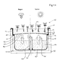
- Embodiment of the device 10 according to the invention for Arranging plants is made up of two modules 100,101 composed, with one module 100 in the other Module 101 is used conclusively and at one inner edge of the other module 101, referred to as paragraph 12 is trained, is supported.
- the module 101 is as integrally formed shell element, the paragraph 12, as can be seen in particular from FIG. 1, with a A plurality of holes 14 is provided, which is a function as a water drain for excess water in the inner free space 13 forming a water reservoir have.
- the free space 13 for receiving water points a floor 15, at the lowest point one Valve device 16 is provided for draining water is.
- the shell element 101 is designed so that it is a Contains wall 17, in which is supported on the paragraph 12
- Module 100 is used conclusively, the module 100 an upwardly open hollow body for receiving a Majority of plants or their root system Substance forms.
- the plants or their roots holding substance made of earth, gravel, or porous Ceramic balls can be formed is for the sake of Clarity not shown in the figures. It is understood, however, that in the invention Device 10 plants to be arranged individually or to Units summarized, anywhere above the frame device 18 within that not shown Substance can be placed.
- the wall 17 has one Flange, which is designed so that the Device 10 according to the invention in total in one appropriately trained holding device 20, the is preferably arranged in the ground, can be supported.
- the device 10 for arranging Planting creates a water-permeable interior Frame device 18, which is the bottom of the module 100 is trained that due to rain or artificial Irrigation in the above the frame device 18th intended, not shown, the plants in question holding substance penetrated excess water through the holes 19 of the frame device 18 in the Water reservoir forming free space 13 drips and there one Water supply forms.
- This water supply can run through artificially introduced additional water enlarged or alternatively only from artificially initiated Water.
- the existing in the free space 13 Water supply forms a reservoir for nutrient water for in the Plants not shown substance, where this nutrient water over from fleece-like materials formed communication links through holes 14 are listed in paragraph 12, and in Water inlet devices 21 open into which the plants holding substance is introduced.
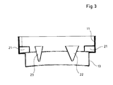
- Vase devices 22, 23 for cut flowers in the Frame device 18 are arranged, the one Communication link to a reservoir included, such as shown in Figure 3.
- the Underside surface 12 of the frame device 11 is permeable to water in such a way that a A plurality of holes 12 'is formed in it, the Holes 12 'are circular and one Have a diameter of 2 mm.
- the shell 15 has a shoulder 19 which is concave is formed, being in the concave cavity of the heel 19 a rubber sealing ring 19 'is provided, on which the underside 12 of the frame device 11 is mounted.
- the shell 15 has one in its central area Water drainage device 17, whose open end 17 'so is provided high above the bottom 15 'of the shell 15, that there is a sufficient amount of water inside the bowl 15 place to stay even over long periods of time sufficient water reservoir for several months form, the natural evaporation pressure of the stored water 16 water vapor generated by the Holes 12 'of the frame device 11 a Water communication link between the shell 15 and the substance 14 contained in the frame device 11 manufactures.
- the upper edge 17 ′ of the water drainage device 17 is furthermore so far below the underside surface 12 the frame device 11 provided that ensured is that the bottom surface 12 is not different from that in the Shell 15 stored water 16 is wetted.
- the device according to the invention acts in such a way that with natural rainfall, like on the left shown in Figure 1, rainwater through the Root system of plant-holding substance 14 seeps and then through the holes 12 'in the bottom surface 12 of the frame device 11 reaches the shell 15.
- rainwater through the Root system of plant-holding substance 14 seeps and then through the holes 12 'in the bottom surface 12 of the frame device 11 reaches the shell 15.
Landscapes
- Life Sciences & Earth Sciences (AREA)
- Environmental Sciences (AREA)
- Engineering & Computer Science (AREA)
- Water Supply & Treatment (AREA)
- Cultivation Receptacles Or Flower-Pots, Or Pots For Seedlings (AREA)
Abstract
Description
- Fig.1
- eine bevorzugte Ausführungsform des Schalenelements gemäß dem ersten Aspekt der erfindungsgemäßen Vorrichtung zum Anordnen von Pflanzen, in einer Ansicht von schräg oben;
- Fig.2
- das in Fig. 1 dargestellte Schalenelement zusammen mit einer inneren Rahmeneinrichtung, in einer Ansicht von schräg oben;
- Fig.3
- das in Fig. 2 dargestellte Schalenelement in einer Querschnittsansicht.
- Fig.1A
- eine bevorzugten Ausführungsform der erfindungsgemäßen Vorrichtung gemäß dem zweiten erfindungsgemäßen Konzept, in einer Querschnittsansicht;
- Fig.2A
- die in Fig. 1A dargestellte Ausführungsform der erfindungsgemäßen Vorrichtung in einer teilweise geschnittenen Ansicht von schräg oben.
Claims (31)
- Vorrichtung zum Anordnen von Pflanzen, mit einem Schalenelement zur Aufnahme der Pflanzen sowie einer das Wurzelwerk der Pflanzen haltenden Substanz, dadurch gekennzeichnet, daß das Schalenelement eine wasserdurchlässige innere Rahmeneinrichtung enthält, oberhalb derer die das Wurzelwerk der Pflanzen haltende Substanz vorgesehen ist, und unterhalb derer ein ein Wasserreservoir bildender Freiraum zur Aufnahme von Wasser vorgesehen ist, und eine Kommunikationsverbindung zwischen dem Reservoir und der Substanz vorgesehen ist.
- Vorrichtung nach Anspruch 1, dadurch gekennzeichnet, daß eine oder mehr Wasserableiteinrichtung vorgesehen sind, mittels derer überschüssiges Wasser aus dem ein Wasserreservoir bildenden Freiraum ableitbar ist.
- Vorrichtung nach Anspruch 2, dadurch gekennzeichnet, daß die Rahmeneinrichtung auf einem innerhalb des Schalelements ausgebildeten Absatz gelagert ist, wobei die eine oder mehr Wasserableiteinrichtung für überschüssiges Wasser aus dem ein Wasserreservoir bildenden Freiraum durch den Absatz geführt ist.
- Vorrichtung nach einem der vorhergehenden Ansprüche, dadurch gekennzeichnet, daß eine Kommunikationsverbindung eine oder mehr Wassereinleiteinrichtungen mit einer Öffnung zum Einleiten von Wasser in das Schalenelement enthält, die oberhalb der Rahmeneinrichtung innerhalb der das Wurzelwerk der Pflanzen haltenden Substanz angeordnet sind, und zusätzlich Einrichtungen enthält, die Wasserverbindung zwischen der einen oder mehr Wassereinleiteinrichtungen zu dem einen Reservoir und/oder einem weiteren Reservoir bewirken.
- Vorrichtung nach Anspruch 4, dadurch gekennzeichnet, daß die zusätzlichen Einrichtungen durch Kapillarien gebildet sind.
- Vorrichtung nach Anspruch 4, dadurch gekennzeichnet, daß die zusätzlichen Einrichtungen durch Vliesmaterialien gebildet sind.
- Vorrichtung nach Anspruch 4, dadurch gekennzeichnet, daß die zusätzlichen Einrichtungen durch mindestens eine elektrische Pumpe gebildet sind.
- Vorrichtung nach einem der vorhergehenden Ansprüche, dadurch gekennzeichnet, daß das eine Reservoir eine Ventileinrichtung zum Ablassen von Wasser enthält.
- Vorrichtung nach einem der vorhergehenden Ansprüche, dadurch gekennzeichnet, daß die Vorrichtung aus zwei Modulen zusammengesetzt, wobei das eine Modul in das andere Modul schlüssig einsetzbar ist und in eingesetztem Zustand an einer inneren Kante des anderen Moduls abgestützt ist.
- Vorrichtung nach einem der vorhergehenden Ansprüche, dadurch gekennzeichnet, daß das Schalenelement einen äußeren Flansch aufweist, mittels dessen dieses an einer Halteeinrichtung abstützbar ist.
- Vorrichtung nach Anspruch 10, dadurch gekennzeichnet, daß die Halteeinrichtung im Erdreich angeordnet ist.
- Vorrichtung nach einem der vorhergehenden Ansprüche, dadurch gekennzeichnet, daß die Rahmeneinrichtung einen äußeren Flansch aufweist, mittels dessen sie an dem Schalenelement abstützbar ist.
- Vorrichtung nach einem der vorhergehenden Ansprüche, dadurch gekennzeichnet, daß die Wasserdurchlässigkeit der Rahmeneinrichtung durch darin ausgebildete Bohrungen erzeugt ist.
- Vorrichtung nach einem der vorhergehenden Ansprüche, dadurch gekennzeichnet, daß Vaseneinrichtungen für Schnittblumen in der Rahmeinrichtung angeordnet sind, die eine Kommunikationsverbindung zu einem Reservoir enthalten.
- Vorrichtung nach einem der vorhergehenden Ansprüche, dadurch gekennzeichnet, daß Aufnahmeeinrichtungen für beliebige Gestaltungselemente in der Rahmeinrichtung angeordnet sind, die eine Kommunikationsverbindung zu einem Reservoir enthalten.
- Vorrichtung zum Anordnen von Pflanzen, mit einem Schalenelement zur Aufnahme der Pflanzen sowie einer das Wurzelwerk der Pflanzen haltenden Substanz, dadurch gekennzeichnet, daß das Schalenelement eine an mindestens ihrer Unterseite wasserdurchlässige Rahmeneinrichtung zur Aufnahme der das Wurzelwerkes der Pflanzen haltenden Substanz enthält, unterhalb derer eine in Richtung auf die Unterseite der Rahmeneinrichtung zu offen ausgebildete Schale zur Aufnahme von Wasser vorgesehen ist, wobei der natürliche Verdampfungsdruck des in der Schale gespeicherten Wassers Wasserdampf erzeugt, der eine Wasser-Kommunikationsverbindung zwischen der Schale und der in der Rahmeneinrichtung enthaltenen Substanz herstellt.
- Vorrichtung nach Anspruch 16, dadurch gekennzeichnet, daß die Rahmeneinrichtung mit der Schale wasserdicht lösbar verbindbar ist.
- Vorrichtung nach Anspruch 17, dadurch gekennzeichnet, daß zur Ausbildung einer wasserdichten lösbaren Verbindung zwischen der Rahmeneinrichtung und der Schale ein Dichtungsring aus Gummi vorgesehen ist.
- Vorrichtung nach Anspruch 16, dadurch gekennzeichnet, daß die Rahmeneinrichtung mit der Schale einstückig ausgebildet ist.
- Vorrichtung nach Anspruch einem der vorhergehenden Ansprüche, dadurch gekennzeichnet, daß Unterseite der Rahmeneinrichtung zum Herbeiführen einer Wasserdurchlässigkeit mit Löchern versehen ist, wobei die Löcher in der Rahmeneinrichtung rund ausgebildet sind.
- Vorrichtung nach Anspruch einem der vorhergehenden Ansprüche, dadurch gekennzeichnet, daß Unterseite der Rahmeneinrichtung zum Herbeiführen einer Wasserdurchlässigkeit mit Löchern versehen ist, wobei die Löcher in der Rahmeneinrichtung eckig ausgebildet sind.
- Vorrichtung nach Anspruch einem der Ansprüche 20 oder 21, dadurch gekennzeichnet, daß die Löcher in der Rahmeneinrichtung einen Durchmesser im Bereich von 2 mm bis 20 mm aufweisen.
- Vorrichtung nach Anspruch einem der vorhergehenden Ansprüche, dadurch gekennzeichnet, daß die Rahmeneinrichtung auf einem innerhalb der Schale ausgebildeten Absatz gelagert ist.
- Vorrichtung nach einem der vorhergehenden Ansprüche, dadurch gekennzeichnet, daß eine oder mehr Wasserableiteinrichtung für in der Schale befindliches überschüssiges Wasser vorgesehen ist.
- Vorrichtung nach Anspruch 24, dadurch gekennzeichnet, daß die Wasserableiteinrichtung durch den Absatz der Schale geführt ist.
- Vorrichtung nach einem der vorhergehenden Ansprüche, dadurch gekennzeichnet, daß das die Schale eine Ventileinrichtung zum Ablassen von Wasser enthält.
- Vorrichtung nach einem der vorhergehenden Ansprüche, dadurch gekennzeichnet, daß die Außenwand der Schale so bemessen ist, daß sie bündig mit der Außenwand der Rahmeneinrichtung verläuft.
- Vorrichtung nach Anspruch 27, dadurch gekennzeichnet, daß die Außenwände der Schale und der Rahmeneinrichtung bündig verlaufen.
- Vorrichtung nach einem der vorhergehenden Ansprüche, dadurch gekennzeichnet, daß die Rahmeneinrichtung und die Schale jeweils als Modul ausgebildet sind, wobei das die Rahmeneinrichtung bildende Modul schlüssig in das die Schale bildende andere Modul einsetzbar ist und in eingesetztem Zustand an einer inneren Kante des anderen Moduls abgestützt ist.
- Vorrichtung nach einem der vorhergehenden Ansprüche, dadurch gekennzeichnet, daß dem in der Schale befindlichen Wasser eine keimtötende Substanz mit niedrigem Dampfdruck beigemischt ist.
- Vorrichtung nach einem der vorhergehenden Ansprüche, dadurch gekennzeichnet, daß zwischen die das Wurzelwerk der Pflanzen haltende Substanz und der Unterseite der Rahmeneinrichtung ein wasseraufnahmefähiges Vliesmaterial vorgesehen ist.
Applications Claiming Priority (4)
| Application Number | Priority Date | Filing Date | Title |
|---|---|---|---|
| DE19927855 | 1999-06-18 | ||
| DE19927855 | 1999-06-18 | ||
| DE19934309A DE19934309C2 (de) | 1999-06-18 | 1999-07-21 | Anordnungsvorrichtung für Pflanzen |
| DE19934309 | 1999-07-21 |
Publications (3)
| Publication Number | Publication Date |
|---|---|
| EP1060655A2 true EP1060655A2 (de) | 2000-12-20 |
| EP1060655A3 EP1060655A3 (de) | 2001-07-18 |
| EP1060655B1 EP1060655B1 (de) | 2004-11-03 |
Family
ID=26053832
Family Applications (1)
| Application Number | Title | Priority Date | Filing Date |
|---|---|---|---|
| EP99118130A Expired - Lifetime EP1060655B1 (de) | 1999-06-18 | 1999-09-11 | Pflanzenzuchtvorrichtung |
Country Status (2)
| Country | Link |
|---|---|
| EP (1) | EP1060655B1 (de) |
| AT (1) | ATE281064T1 (de) |
Cited By (6)
| Publication number | Priority date | Publication date | Assignee | Title |
|---|---|---|---|---|
| US7278238B2 (en) * | 2003-09-05 | 2007-10-09 | Kristine Ann Maniscalco | False bottom insert assembly for an oversized planter container |
| CN102257928A (zh) * | 2010-12-20 | 2011-11-30 | 陈国柱 | 一种水田 |
| EP1642493A4 (de) * | 2003-06-13 | 2013-03-06 | Kawada Construction Co Ltd | Begrünungsvorrichtung |
| CN112167031A (zh) * | 2020-10-14 | 2021-01-05 | 杨银排 | 一种垂直建筑种植台自浇灌装置 |
| CN113080049A (zh) * | 2021-04-30 | 2021-07-09 | 深圳市蔬心宝科技有限公司 | 新型基质育苗盘、育苗系统及育苗方法 |
| US12534393B2 (en) | 2022-12-07 | 2026-01-27 | Contech Engineered Solutions LLC | Stormwater collection system with filtration, retention and irrigation of live plantings |
Family Cites Families (7)
| Publication number | Priority date | Publication date | Assignee | Title |
|---|---|---|---|---|
| GB1010941A (en) * | 1961-06-20 | 1965-11-24 | Duncan Tong | Improvements in and relating to flower pots or vases |
| US3800471A (en) * | 1973-04-16 | 1974-04-02 | Adams R Olympia | Flower pot with water reservoir |
| US3903641A (en) * | 1973-08-31 | 1975-09-09 | Louis S Hoffman | Moisture responsive tilting planter |
| DE3446677A1 (de) * | 1984-12-21 | 1986-10-02 | Hubert K. 5275 Bergneustadt Block | Selbstversorgungs-vorrichtung fuer alle pflanzen, gewaechse und blumen in der erd-, hydro-, hetero- und bonsaikultur |
| FR2648011A1 (fr) * | 1989-06-07 | 1990-12-14 | Bouchacourt Jean | Cabine de culture hydroponique perfectionnee |
| DE4431436A1 (de) * | 1994-09-03 | 1996-03-07 | Manfred Luik | Vorrichtung zur Pflanzenpflege |
| DE29608418U1 (de) * | 1996-05-09 | 1996-08-01 | Hundbiss, Wolfgang, 89257 Illertissen | Pflanzgefäßsystem mit integrierter Selbstbewässerung |
-
1999
- 1999-09-11 EP EP99118130A patent/EP1060655B1/de not_active Expired - Lifetime
- 1999-09-11 AT AT99118130T patent/ATE281064T1/de active
Non-Patent Citations (1)
| Title |
|---|
| None |
Cited By (7)
| Publication number | Priority date | Publication date | Assignee | Title |
|---|---|---|---|---|
| EP1642493A4 (de) * | 2003-06-13 | 2013-03-06 | Kawada Construction Co Ltd | Begrünungsvorrichtung |
| US8701345B2 (en) | 2003-06-13 | 2014-04-22 | Kawada Construction Co., Ltd. | Greening system |
| US7278238B2 (en) * | 2003-09-05 | 2007-10-09 | Kristine Ann Maniscalco | False bottom insert assembly for an oversized planter container |
| CN102257928A (zh) * | 2010-12-20 | 2011-11-30 | 陈国柱 | 一种水田 |
| CN112167031A (zh) * | 2020-10-14 | 2021-01-05 | 杨银排 | 一种垂直建筑种植台自浇灌装置 |
| CN113080049A (zh) * | 2021-04-30 | 2021-07-09 | 深圳市蔬心宝科技有限公司 | 新型基质育苗盘、育苗系统及育苗方法 |
| US12534393B2 (en) | 2022-12-07 | 2026-01-27 | Contech Engineered Solutions LLC | Stormwater collection system with filtration, retention and irrigation of live plantings |
Also Published As
| Publication number | Publication date |
|---|---|
| EP1060655B1 (de) | 2004-11-03 |
| ATE281064T1 (de) | 2004-11-15 |
| EP1060655A3 (de) | 2001-07-18 |
Similar Documents
| Publication | Publication Date | Title |
|---|---|---|
| DE60101374T2 (de) | Behälter für die Kultivierung von Pflanzen | |
| DE3538162C2 (de) | Selbsttätige Bewässerungsvorrichtung für bepflanzte Erde | |
| EP2904895B1 (de) | System zur vertikalen Begrünung | |
| DE2754838C2 (de) | ||
| EP3836777B1 (de) | Pflanzvorrichtung | |
| EP1060655A2 (de) | Pflanzenzuchtvorrichtung | |
| DE4403836A1 (de) | Vorrichtung zum selbsttätigen Befeuchten von Kulturen in Gefäßen oder dergleichen | |
| DE2253906A1 (de) | Gartenanlage | |
| DE3816866A1 (de) | Begruenungselement | |
| DE3600340A1 (de) | Vorrichtung zur belueftung und feuchtigkeitsregulierung des wurzelraumes von stadtbaeumen und verwendung dieser vorrichtung bei neupflanzungen | |
| WO2008086796A1 (de) | Urne, insbesondere zur erdbeisetzung, und erdbeisetzungsverfahren | |
| DE3523004A1 (de) | Vorrichtung zur langzeitversorgung von pflanzen | |
| EP4190144A1 (de) | Mediumdurchströmbarer körper sowie begrünungssystem mit zumindest einem solchen mediumdurchströmbaren körper | |
| DE19934309A1 (de) | Anordnungsvorrichtung für Pflanzen | |
| EP0692573A1 (de) | Kulturflächen-Anordnung und Verfahren zu deren Versorgung, insbesondere Bewässerung | |
| AT398021B (de) | Selbsttätige bewässerungsvorrichtung für bepflanzte erde | |
| DE3633390A1 (de) | Behaelter fuer pflanzen und gewaechse zur begruenung von insbesondere trockenen standorten u. verfahren zur anzucht von pflanzen und gewaechsen mittels des behaelters | |
| DE3438103C2 (de) | ||
| DE4233620C2 (de) | Pflanzenversorgungsvorrichtung | |
| EP4649819A1 (de) | Pflanzenbehälter | |
| DE102007039042A1 (de) | Bewässerungssystem für Pflanzen sowie Bausatz zur Herstellung eines Bewässerungssystems | |
| DE19749673A1 (de) | Unterirdisches Bewässerungssystem für Friedhofsanlagen, private und öffentliche Bepflanzungen | |
| DE20122520U1 (de) | Vorrichtung zur Bewässerung eines Pflanzenbehälters | |
| DE3344945A1 (de) | Verfahren und vorrichtung zur erdlosen aufzucht und kultivierung von pflanzen auf schiefen ebenen, vorzugsweise im freien | |
| DE8203635U1 (de) | Bewässerungsvorrichtung für Topfpflanzen |
Legal Events
| Date | Code | Title | Description |
|---|---|---|---|
| PUAI | Public reference made under article 153(3) epc to a published international application that has entered the european phase |
Free format text: ORIGINAL CODE: 0009012 |
|
| AK | Designated contracting states |
Kind code of ref document: A2 Designated state(s): AT BE CH CY DE DK ES FI FR GB GR IE IT LI LU MC NL PT SE |
|
| AX | Request for extension of the european patent |
Free format text: AL;LT;LV;MK;RO;SI |
|
| PUAL | Search report despatched |
Free format text: ORIGINAL CODE: 0009013 |
|
| AK | Designated contracting states |
Kind code of ref document: A3 Designated state(s): AT BE CH CY DE DK ES FI FR GB GR IE IT LI LU MC NL PT SE |
|
| AX | Request for extension of the european patent |
Free format text: AL;LT;LV;MK;RO;SI |
|
| 17P | Request for examination filed |
Effective date: 20020116 |
|
| AKX | Designation fees paid |
Free format text: AT BE CH CY DE DK ES FI FR GB GR IE IT LI LU MC NL PT SE |
|
| 17Q | First examination report despatched |
Effective date: 20030707 |
|
| GRAP | Despatch of communication of intention to grant a patent |
Free format text: ORIGINAL CODE: EPIDOSNIGR1 |
|
| GRAS | Grant fee paid |
Free format text: ORIGINAL CODE: EPIDOSNIGR3 |
|
| GRAA | (expected) grant |
Free format text: ORIGINAL CODE: 0009210 |
|
| AK | Designated contracting states |
Kind code of ref document: B1 Designated state(s): AT BE CH CY DE DK ES FI FR GB GR IE IT LI LU MC NL PT SE |
|
| PG25 | Lapsed in a contracting state [announced via postgrant information from national office to epo] |
Ref country code: NL Free format text: LAPSE BECAUSE OF FAILURE TO SUBMIT A TRANSLATION OF THE DESCRIPTION OR TO PAY THE FEE WITHIN THE PRESCRIBED TIME-LIMIT Effective date: 20041103 Ref country code: IT Free format text: LAPSE BECAUSE OF FAILURE TO SUBMIT A TRANSLATION OF THE DESCRIPTION OR TO PAY THE FEE WITHIN THE PRE;WARNING: LAPSES OF ITALIAN PATENTS WITH EFFECTIVE DATE BEFORE 2007 MAY HAVE OCCURRED AT ANY TIME BEFORE 2007. THE CORRECT EFFECTIVE DATE MAY BE DIFFERENT FROM THE ONE RECORDED.SCRIBED TIME-LIMIT Effective date: 20041103 Ref country code: IE Free format text: LAPSE BECAUSE OF FAILURE TO SUBMIT A TRANSLATION OF THE DESCRIPTION OR TO PAY THE FEE WITHIN THE PRESCRIBED TIME-LIMIT Effective date: 20041103 Ref country code: GB Free format text: LAPSE BECAUSE OF FAILURE TO SUBMIT A TRANSLATION OF THE DESCRIPTION OR TO PAY THE FEE WITHIN THE PRESCRIBED TIME-LIMIT Effective date: 20041103 Ref country code: FR Free format text: LAPSE BECAUSE OF FAILURE TO SUBMIT A TRANSLATION OF THE DESCRIPTION OR TO PAY THE FEE WITHIN THE PRESCRIBED TIME-LIMIT Effective date: 20041103 Ref country code: FI Free format text: LAPSE BECAUSE OF FAILURE TO SUBMIT A TRANSLATION OF THE DESCRIPTION OR TO PAY THE FEE WITHIN THE PRESCRIBED TIME-LIMIT Effective date: 20041103 |
|
| REG | Reference to a national code |
Ref country code: GB Ref legal event code: FG4D Free format text: NOT ENGLISH |
|
| REG | Reference to a national code |
Ref country code: CH Ref legal event code: EP |
|
| REF | Corresponds to: |
Ref document number: 59910995 Country of ref document: DE Date of ref document: 20041209 Kind code of ref document: P |
|
| REG | Reference to a national code |
Ref country code: IE Ref legal event code: FG4D Free format text: GERMAN |
|
| PG25 | Lapsed in a contracting state [announced via postgrant information from national office to epo] |
Ref country code: SE Free format text: LAPSE BECAUSE OF FAILURE TO SUBMIT A TRANSLATION OF THE DESCRIPTION OR TO PAY THE FEE WITHIN THE PRESCRIBED TIME-LIMIT Effective date: 20050203 Ref country code: GR Free format text: LAPSE BECAUSE OF FAILURE TO SUBMIT A TRANSLATION OF THE DESCRIPTION OR TO PAY THE FEE WITHIN THE PRESCRIBED TIME-LIMIT Effective date: 20050203 Ref country code: DK Free format text: LAPSE BECAUSE OF FAILURE TO SUBMIT A TRANSLATION OF THE DESCRIPTION OR TO PAY THE FEE WITHIN THE PRESCRIBED TIME-LIMIT Effective date: 20050203 |
|
| PG25 | Lapsed in a contracting state [announced via postgrant information from national office to epo] |
Ref country code: ES Free format text: LAPSE BECAUSE OF FAILURE TO SUBMIT A TRANSLATION OF THE DESCRIPTION OR TO PAY THE FEE WITHIN THE PRESCRIBED TIME-LIMIT Effective date: 20050214 |
|
| REG | Reference to a national code |
Ref country code: CH Ref legal event code: NV Representative=s name: ISLER & PEDRAZZINI AG |
|
| NLV1 | Nl: lapsed or annulled due to failure to fulfill the requirements of art. 29p and 29m of the patents act | ||
| GBV | Gb: ep patent (uk) treated as always having been void in accordance with gb section 77(7)/1977 [no translation filed] |
Effective date: 20041103 |
|
| REG | Reference to a national code |
Ref country code: IE Ref legal event code: FD4D |
|
| PLBE | No opposition filed within time limit |
Free format text: ORIGINAL CODE: 0009261 |
|
| STAA | Information on the status of an ep patent application or granted ep patent |
Free format text: STATUS: NO OPPOSITION FILED WITHIN TIME LIMIT |
|
| PG25 | Lapsed in a contracting state [announced via postgrant information from national office to epo] |
Ref country code: CY Free format text: LAPSE BECAUSE OF FAILURE TO SUBMIT A TRANSLATION OF THE DESCRIPTION OR TO PAY THE FEE WITHIN THE PRESCRIBED TIME-LIMIT Effective date: 20050911 |
|
| PG25 | Lapsed in a contracting state [announced via postgrant information from national office to epo] |
Ref country code: MC Free format text: LAPSE BECAUSE OF NON-PAYMENT OF DUE FEES Effective date: 20050930 Ref country code: LU Free format text: LAPSE BECAUSE OF NON-PAYMENT OF DUE FEES Effective date: 20050930 Ref country code: BE Free format text: LAPSE BECAUSE OF NON-PAYMENT OF DUE FEES Effective date: 20050930 |
|
| 26N | No opposition filed |
Effective date: 20050804 |
|
| EN | Fr: translation not filed | ||
| PG25 | Lapsed in a contracting state [announced via postgrant information from national office to epo] |
Ref country code: DE Free format text: LAPSE BECAUSE OF NON-PAYMENT OF DUE FEES Effective date: 20060401 |
|
| REG | Reference to a national code |
Ref country code: CH Ref legal event code: PCAR Free format text: ISLER & PEDRAZZINI AG;POSTFACH 1772;8027 ZUERICH (CH) |
|
| BERE | Be: lapsed |
Owner name: *L & L PROBOX G.M.B.H. Effective date: 20050930 |
|
| PG25 | Lapsed in a contracting state [announced via postgrant information from national office to epo] |
Ref country code: PT Free format text: LAPSE BECAUSE OF NON-PAYMENT OF DUE FEES Effective date: 20050403 |
|
| REG | Reference to a national code |
Ref country code: CH Ref legal event code: PUE Owner name: EMSA GMBH Free format text: L & L PROBOX GMBH#BACHSTRASSE 7#89617 UNTERMARCHTAL (DE) -TRANSFER TO- EMSA GMBH#GREVENER DAMM 215-225#48282 EMSDETTEN (DE) |
|
| PGFP | Annual fee paid to national office [announced via postgrant information from national office to epo] |
Ref country code: CH Payment date: 20110923 Year of fee payment: 13 |
|
| PGFP | Annual fee paid to national office [announced via postgrant information from national office to epo] |
Ref country code: AT Payment date: 20110914 Year of fee payment: 13 |
|
| REG | Reference to a national code |
Ref country code: CH Ref legal event code: PL |
|
| REG | Reference to a national code |
Ref country code: AT Ref legal event code: MM01 Ref document number: 281064 Country of ref document: AT Kind code of ref document: T Effective date: 20120911 |
|
| PG25 | Lapsed in a contracting state [announced via postgrant information from national office to epo] |
Ref country code: CH Free format text: LAPSE BECAUSE OF NON-PAYMENT OF DUE FEES Effective date: 20120930 Ref country code: LI Free format text: LAPSE BECAUSE OF NON-PAYMENT OF DUE FEES Effective date: 20120930 Ref country code: AT Free format text: LAPSE BECAUSE OF NON-PAYMENT OF DUE FEES Effective date: 20120911 |