EP1060665A2 - Stützklammer - Google Patents
Stützklammer Download PDFInfo
- Publication number
- EP1060665A2 EP1060665A2 EP00201719A EP00201719A EP1060665A2 EP 1060665 A2 EP1060665 A2 EP 1060665A2 EP 00201719 A EP00201719 A EP 00201719A EP 00201719 A EP00201719 A EP 00201719A EP 1060665 A2 EP1060665 A2 EP 1060665A2
- Authority
- EP
- European Patent Office
- Prior art keywords
- support clip
- jaws
- another
- pivots
- clip
- Prior art date
- Legal status (The legal status is an assumption and is not a legal conclusion. Google has not performed a legal analysis and makes no representation as to the accuracy of the status listed.)
- Withdrawn
Links
- 230000006835 compression Effects 0.000 claims description 4
- 238000007906 compression Methods 0.000 claims description 4
- 230000004048 modification Effects 0.000 claims description 3
- 238000012986 modification Methods 0.000 claims description 3
- 238000010276 construction Methods 0.000 description 3
- 239000000463 material Substances 0.000 description 2
- 238000010079 rubber tapping Methods 0.000 description 2
- 229910001220 stainless steel Inorganic materials 0.000 description 2
- 239000010935 stainless steel Substances 0.000 description 2
- 229920002725 thermoplastic elastomer Polymers 0.000 description 2
- 229910001369 Brass Inorganic materials 0.000 description 1
- 239000004677 Nylon Substances 0.000 description 1
- 239000004743 Polypropylene Substances 0.000 description 1
- 239000010951 brass Substances 0.000 description 1
- 239000011521 glass Substances 0.000 description 1
- 229920001778 nylon Polymers 0.000 description 1
- 239000004033 plastic Substances 0.000 description 1
- 229920003023 plastic Polymers 0.000 description 1
- -1 polypropylene Polymers 0.000 description 1
- 229920001155 polypropylene Polymers 0.000 description 1
Images




Classifications
-
- F—MECHANICAL ENGINEERING; LIGHTING; HEATING; WEAPONS; BLASTING
- F16—ENGINEERING ELEMENTS AND UNITS; GENERAL MEASURES FOR PRODUCING AND MAINTAINING EFFECTIVE FUNCTIONING OF MACHINES OR INSTALLATIONS; THERMAL INSULATION IN GENERAL
- F16B—DEVICES FOR FASTENING OR SECURING CONSTRUCTIONAL ELEMENTS OR MACHINE PARTS TOGETHER, e.g. NAILS, BOLTS, CIRCLIPS, CLAMPS, CLIPS OR WEDGES; JOINTS OR JOINTING
- F16B2/00—Friction-grip releasable fastenings
- F16B2/02—Clamps, i.e. with gripping action effected by positive means other than the inherent resistance to deformation of the material of the fastening
- F16B2/06—Clamps, i.e. with gripping action effected by positive means other than the inherent resistance to deformation of the material of the fastening external, i.e. with contracting action
- F16B2/10—Clamps, i.e. with gripping action effected by positive means other than the inherent resistance to deformation of the material of the fastening external, i.e. with contracting action using pivoting jaws
-
- A—HUMAN NECESSITIES
- A01—AGRICULTURE; FORESTRY; ANIMAL HUSBANDRY; HUNTING; TRAPPING; FISHING
- A01K—ANIMAL HUSBANDRY; AVICULTURE; APICULTURE; PISCICULTURE; FISHING; REARING OR BREEDING ANIMALS, NOT OTHERWISE PROVIDED FOR; NEW BREEDS OF ANIMALS
- A01K97/00—Accessories for angling
- A01K97/10—Supports for rods
-
- F—MECHANICAL ENGINEERING; LIGHTING; HEATING; WEAPONS; BLASTING
- F16—ENGINEERING ELEMENTS AND UNITS; GENERAL MEASURES FOR PRODUCING AND MAINTAINING EFFECTIVE FUNCTIONING OF MACHINES OR INSTALLATIONS; THERMAL INSULATION IN GENERAL
- F16B—DEVICES FOR FASTENING OR SECURING CONSTRUCTIONAL ELEMENTS OR MACHINE PARTS TOGETHER, e.g. NAILS, BOLTS, CIRCLIPS, CLAMPS, CLIPS OR WEDGES; JOINTS OR JOINTING
- F16B45/00—Hooks; Eyes
- F16B45/06—Hooks with two symmetrically-pivoting hook parts within the same locking cavity
Definitions
- the present invention relates to a support clip having jaws which are resiliently urged towards one another when forcibly moved apart from one another.
- One such clip is described and illustrateed in GB 2,178,282. It comprises a clip of generally U-shaped section which is resilient so that the two arms of the U-shape, when forcibly moved apart from one another, are urged back to their normal rest position by virtue of the natural resilience of the material of the clip.
- a problem encountered with such a clip is that it does not readily receive elongate members, such as fishing rods, of widely varying cross-sectional diameters.
- the present invention seeks to obviate this disadvantage.
- the present invention is directed to a support clip having the features set out in the opening paragraph of the present specification, in which adjustment means are arranged in relation to the jaws to enable their normal rest positions relative to one another to be adjusted.
- Such a construction is especially valuable as a fishing rod support clip.
- the jaws are pivotable about respective pivots provided as parts of the support clip.
- pivots may comprise pivot pins.
- the adjustment may be effected by means of a screw. This may extend between the pivot pins such that rotation of the screw causes the pins to be moved towards or away from one another in a direction which is transverse of the axes of the pins.
- a restoring force to resiliently urge them back towards one another may be provided by a compression spring positioned between portions which are respectively fixed in relation to the jaws and which are located on the opposite sides of the pivots relative to the jaws.
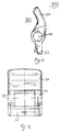
- the support clip 10 shown in Figures 1 to 4 is a fishing rod support clip comprising a brass screw-threaded stem 12 to enable the clip to be secured to the upper end of a correspondingly screw-threaded bank-stick or buzz-bar, a mounting pivot 14 to enable the clip to be pivoted relative to the bank-stick through approximately 20°, to suit conditions, about an axis which is generally transverse of a fishing rod when it is held by clip, and a support base 16 pivotally mounted on the pivot 40.
- the support base 16 is made of a yieldable polypropylene plastics material.
- the base 16 is generally U-shaped in section with respective arms 17 extending in an intended upward direction. It is shown more clearly in Figures 5 to 8.
- Two rings 18 are formed on the base 16 integrally therewith and located on an intended upper end of each arm 17.
- the clip has two jaws 20, each being arcuate in section with their concave faces directed towards one another.
- Each jaw 20 is made of glass filled nylon (GFN) and covered with a thermoplastic rubber (TPR), such as Evoprene (TM), at its intended upper end to improve the ability of the jaws to grip a fishing rod.
- Lugs 21 which are integral with the jaws 20 are connected by bridging portions 22, as can be seen more clearly from Figures 9 to 13.
- a hole 24 of circular section extends through two portions 22 of each jaw 20 (as again can be seen more clearly from Figures 9 to 13). The diameter of the hole 24 is the same as the internal diameter of each ring 18.
- a pivot pin 26 extends through the hole 24 of each jaw 20 and also through an associated pair of rings 18 so that the jaws 20 pivot about the ends of the arms 17 of the base 16 respectively.
- the lugs 21 are urged apart by a stainless steel compressing spring 30 extending between the lugs 21, the spring being located on each lug 21 by a respective spigot 31.
- Stops 32 project upwardly from the base 16 to protect the spring 30 and to act as abutment stops to limit the outward pivotable movement of the jaws 20.
- a stainless steel tapping screw 34 extends between and through the two pivot pins 26. Its head 36 rests on the outside of one of the pins 26, and its opposite end screw-threadingly engages a collar 38 which surrounds the other pin 26. The head of the screw 36 is accessible between two rings 18, as shown in Figure 2.
- a portion of a fishing rod having a cross-sectional diameter of 20mm can be held between the jaws 20.
- the selected part of the rod can be pushed downwardly between the jaws so that the latter are urged away from one another against the restoring force of the compression spring 30 until the full diameter of that part of the rod passes the ends of the jaws 20, whereupon the latter move towards one another under the action of the compression spring 30 until that part of the rod is held snugly between the jaws 20.
- the tapping screw 36 can be rotated to draw the two pivot pins 26 closer together with the base 16 yielding resiliently to facilitate this, as shown in Figure 4, so that now a part of a fishing rod having a diameter as low as 13mm can be satisfactorily held by the same clip 10. This can be done readily, precisely, and without any need to dismantle the clip 10.
- the limited freedom of rotation of the clip about the pivot 14 ensures that the fishing rod can be readily removed from the clip 10, by orienting the rod through an angle beyond the freedom of rotation provided by the pivot 14.
- the pivots 26 could be entirely omitted as well as the spring 30, and the jaws may be constituted by upwardly extending portions of the arms 17. These may be made sufficiently resilient to provide for the restoring force desired.
- a screw like the one labelled 34 could extend and engage lower portions of the arms 17 to enable them to be drawn together or moved apart.
Landscapes
- Engineering & Computer Science (AREA)
- General Engineering & Computer Science (AREA)
- Mechanical Engineering (AREA)
- Life Sciences & Earth Sciences (AREA)
- Environmental Sciences (AREA)
- Animal Husbandry (AREA)
- Biodiversity & Conservation Biology (AREA)
Applications Claiming Priority (2)
| Application Number | Priority Date | Filing Date | Title |
|---|---|---|---|
| GBGB9911182.5A GB9911182D0 (en) | 1999-05-13 | 1999-05-13 | A support clip |
| GB9911182 | 1999-05-13 |
Publications (2)
| Publication Number | Publication Date |
|---|---|
| EP1060665A2 true EP1060665A2 (de) | 2000-12-20 |
| EP1060665A3 EP1060665A3 (de) | 2001-01-03 |
Family
ID=10853438
Family Applications (1)
| Application Number | Title | Priority Date | Filing Date |
|---|---|---|---|
| EP00201719A Withdrawn EP1060665A3 (de) | 1999-05-13 | 2000-05-15 | Stützklammer |
Country Status (2)
| Country | Link |
|---|---|
| EP (1) | EP1060665A3 (de) |
| GB (1) | GB9911182D0 (de) |
Cited By (6)
| Publication number | Priority date | Publication date | Assignee | Title |
|---|---|---|---|---|
| US6487813B2 (en) * | 2000-02-08 | 2002-12-03 | D. Calvin Baynard | Dual position fishing rod holder |
| DE10239620B4 (de) * | 2002-08-29 | 2005-10-27 | Paim Gmbh | Angelhalter |
| US7254915B2 (en) * | 2005-03-03 | 2007-08-14 | John Adam Mrotek | Alligator clip holder for supporting a fishing rod |
| GB2465421A (en) * | 2008-11-20 | 2010-05-26 | Robert Victor Llewellin | Quick release fishing pole support |
| GB2534139A (en) * | 2015-01-12 | 2016-07-20 | Thompson Andrew | Self tensioning clamp |
| GB2569825A (en) * | 2018-01-02 | 2019-07-03 | H Young Operations Ltd | Fishing keepnet attachment |
Citations (1)
| Publication number | Priority date | Publication date | Assignee | Title |
|---|---|---|---|---|
| GB2178282A (en) | 1985-07-31 | 1987-02-11 | Clifford Royston Fox | Fishing rod support means |
Family Cites Families (4)
| Publication number | Priority date | Publication date | Assignee | Title |
|---|---|---|---|---|
| US2566496A (en) * | 1949-05-20 | 1951-09-04 | Montano Domenico | Fisherman's pole rest |
| US2628048A (en) * | 1949-10-03 | 1953-02-10 | William A Mckinney | Fishing rod holder |
| AT273570B (de) * | 1966-12-13 | 1969-08-25 | Hanns Balzer Fa | Angelrutenständer |
| GB2333020A (en) * | 1998-01-10 | 1999-07-14 | Michael Charles Nolan | Support for fishing rods |
-
1999
- 1999-05-13 GB GBGB9911182.5A patent/GB9911182D0/en not_active Ceased
-
2000
- 2000-05-15 EP EP00201719A patent/EP1060665A3/de not_active Withdrawn
Patent Citations (1)
| Publication number | Priority date | Publication date | Assignee | Title |
|---|---|---|---|---|
| GB2178282A (en) | 1985-07-31 | 1987-02-11 | Clifford Royston Fox | Fishing rod support means |
Cited By (6)
| Publication number | Priority date | Publication date | Assignee | Title |
|---|---|---|---|---|
| US6487813B2 (en) * | 2000-02-08 | 2002-12-03 | D. Calvin Baynard | Dual position fishing rod holder |
| DE10239620B4 (de) * | 2002-08-29 | 2005-10-27 | Paim Gmbh | Angelhalter |
| US7254915B2 (en) * | 2005-03-03 | 2007-08-14 | John Adam Mrotek | Alligator clip holder for supporting a fishing rod |
| GB2465421A (en) * | 2008-11-20 | 2010-05-26 | Robert Victor Llewellin | Quick release fishing pole support |
| GB2534139A (en) * | 2015-01-12 | 2016-07-20 | Thompson Andrew | Self tensioning clamp |
| GB2569825A (en) * | 2018-01-02 | 2019-07-03 | H Young Operations Ltd | Fishing keepnet attachment |
Also Published As
| Publication number | Publication date |
|---|---|
| GB9911182D0 (en) | 1999-07-14 |
| EP1060665A3 (de) | 2001-01-03 |
Similar Documents
| Publication | Publication Date | Title |
|---|---|---|
| US4880192A (en) | Handled tool suspension device | |
| US3675359A (en) | Fish mouth implements | |
| WO2004047657A2 (fr) | Dispositif d’ancrage vertebral et son dispositif de blocage sur une vis poly axiale | |
| EP1183146A1 (de) | Verbesserter greifer zum handhaben von vorformlingen | |
| EP0386807A3 (de) | Flankendurchmesser-Messgerät für die Hand | |
| KR102291724B1 (ko) | 농작물 결속용 집게 | |
| JPH05502997A (ja) | 剪定ばさみ | |
| US2891275A (en) | Fish holders | |
| EP0276630A1 (de) | Zubehör für Schier | |
| US7174902B2 (en) | Hair ornament with a resilient attaching clip | |
| US20070131052A1 (en) | Joining device for an actuating lever and supporting element of a valve operating mechanism of an internal combustion engine | |
| EP0801895A2 (de) | An einem Angelrute befestigbare Köderverteiler | |
| EP0897663B1 (de) | Vorrichtung zum lösbaren Halten einer Angelleine | |
| US8864775B2 (en) | Applying forceps for a clip | |
| WO2009147318A1 (fr) | Articulation de branches de lunettes | |
| JPS5943242A (ja) | 高速取付け接続部を備えたガスばね | |
| US4171567A (en) | Nutcracker | |
| US6564494B2 (en) | Fly tying vises | |
| EP0611233B1 (de) | Gerät für Markierungen zum Aufbringen von Identifikationszeichen nach zwei Dimensionen auf der Oberfläche eines Gegenständes | |
| GB2252902A (en) | Garment hanger | |
| US20050103184A1 (en) | Retaining device for a drum | |
| EP1040755B1 (de) | Bissanzeiger für Fische | |
| WO1998017152A3 (de) | Sitzmöbel | |
| FR2587262A1 (fr) | Pince de prehension notamment pour bloc de maconnerie calibre | |
| US4569278A (en) | Cooking implement |
Legal Events
| Date | Code | Title | Description |
|---|---|---|---|
| PUAI | Public reference made under article 153(3) epc to a published international application that has entered the european phase |
Free format text: ORIGINAL CODE: 0009012 |
|
| PUAL | Search report despatched |
Free format text: ORIGINAL CODE: 0009013 |
|
| AK | Designated contracting states |
Kind code of ref document: A2 Designated state(s): GB |
|
| AX | Request for extension of the european patent |
Free format text: AL;LT;LV;MK;RO;SI |
|
| AK | Designated contracting states |
Kind code of ref document: A3 Designated state(s): AT BE CH CY DE DK ES FI FR GB GR IE IT LI LU MC NL PT SE |
|
| AX | Request for extension of the european patent |
Free format text: AL;LT;LV;MK;RO;SI |
|
| 17P | Request for examination filed |
Effective date: 20010626 |
|
| AKX | Designation fees paid |
Free format text: GB |
|
| 17Q | First examination report despatched |
Effective date: 20040219 |
|
| REG | Reference to a national code |
Ref country code: DE Ref legal event code: 8566 |
|
| STAA | Information on the status of an ep patent application or granted ep patent |
Free format text: STATUS: THE APPLICATION IS DEEMED TO BE WITHDRAWN |
|
| 18D | Application deemed to be withdrawn |
Effective date: 20040630 |