EP1060720A1 - Vorrichtung zum formen eines rohrförmigen Körper - Google Patents
Vorrichtung zum formen eines rohrförmigen Körper Download PDFInfo
- Publication number
- EP1060720A1 EP1060720A1 EP00119789A EP00119789A EP1060720A1 EP 1060720 A1 EP1060720 A1 EP 1060720A1 EP 00119789 A EP00119789 A EP 00119789A EP 00119789 A EP00119789 A EP 00119789A EP 1060720 A1 EP1060720 A1 EP 1060720A1
- Authority
- EP
- European Patent Office
- Prior art keywords
- tubular member
- curl
- curling
- curling element
- applicator
- Prior art date
- Legal status (The legal status is an assumption and is not a legal conclusion. Google has not performed a legal analysis and makes no representation as to the accuracy of the status listed.)
- Withdrawn
Links
- 239000000463 material Substances 0.000 description 39
- 239000000123 paper Substances 0.000 description 20
- 239000000126 substance Substances 0.000 description 16
- 210000001215 vagina Anatomy 0.000 description 15
- 239000011800 void material Substances 0.000 description 15
- 210000003811 finger Anatomy 0.000 description 13
- 238000000576 coating method Methods 0.000 description 7
- 230000015572 biosynthetic process Effects 0.000 description 5
- 239000011111 cardboard Substances 0.000 description 5
- 239000003814 drug Substances 0.000 description 5
- 238000003780 insertion Methods 0.000 description 5
- 230000037431 insertion Effects 0.000 description 5
- 239000011087 paperboard Substances 0.000 description 5
- 239000004033 plastic Substances 0.000 description 5
- 239000011248 coating agent Substances 0.000 description 4
- 229940079593 drug Drugs 0.000 description 4
- 210000003813 thumb Anatomy 0.000 description 4
- 238000004804 winding Methods 0.000 description 4
- 241001465754 Metazoa Species 0.000 description 3
- 230000000295 complement effect Effects 0.000 description 3
- 230000006835 compression Effects 0.000 description 3
- 238000007906 compression Methods 0.000 description 3
- 239000000835 fiber Substances 0.000 description 3
- 230000003993 interaction Effects 0.000 description 3
- 230000007246 mechanism Effects 0.000 description 3
- 230000000717 retained effect Effects 0.000 description 3
- 206010017533 Fungal infection Diseases 0.000 description 2
- PXHVJJICTQNCMI-UHFFFAOYSA-N Nickel Chemical compound [Ni] PXHVJJICTQNCMI-UHFFFAOYSA-N 0.000 description 2
- 230000002745 absorbent Effects 0.000 description 2
- 239000002250 absorbent Substances 0.000 description 2
- 230000009471 action Effects 0.000 description 2
- 239000000853 adhesive Substances 0.000 description 2
- 230000001070 adhesive effect Effects 0.000 description 2
- 230000003466 anti-cipated effect Effects 0.000 description 2
- 230000007423 decrease Effects 0.000 description 2
- 239000003292 glue Substances 0.000 description 2
- 238000004519 manufacturing process Methods 0.000 description 2
- 238000000034 method Methods 0.000 description 2
- 238000012986 modification Methods 0.000 description 2
- 230000004048 modification Effects 0.000 description 2
- 230000008569 process Effects 0.000 description 2
- 238000004826 seaming Methods 0.000 description 2
- 239000007787 solid Substances 0.000 description 2
- 229920001169 thermoplastic Polymers 0.000 description 2
- 239000004416 thermosoftening plastic Substances 0.000 description 2
- JIJQKFPGBBEJNF-KBPBESRZSA-N Curlone Natural products CC(C)=CC(=O)C[C@H](C)[C@@H]1CCC(=C)C=C1 JIJQKFPGBBEJNF-KBPBESRZSA-N 0.000 description 1
- 240000007591 Tilia tomentosa Species 0.000 description 1
- XOCANRBEOZQNAQ-KBPBESRZSA-N alpha-turmerone Natural products O=C(/C=C(\C)/C)C[C@H](C)[C@H]1C=CC(C)=CC1 XOCANRBEOZQNAQ-KBPBESRZSA-N 0.000 description 1
- 238000013459 approach Methods 0.000 description 1
- 230000009286 beneficial effect Effects 0.000 description 1
- 239000008280 blood Substances 0.000 description 1
- 210000004369 blood Anatomy 0.000 description 1
- 210000001124 body fluid Anatomy 0.000 description 1
- 239000010839 body fluid Substances 0.000 description 1
- 239000002775 capsule Substances 0.000 description 1
- JIJQKFPGBBEJNF-UHFFFAOYSA-N curlone Chemical compound CC(C)=CC(=O)CC(C)C1CCC(=C)C=C1 JIJQKFPGBBEJNF-UHFFFAOYSA-N 0.000 description 1
- 230000006378 damage Effects 0.000 description 1
- 230000035622 drinking Effects 0.000 description 1
- 239000007888 film coating Substances 0.000 description 1
- 238000009501 film coating Methods 0.000 description 1
- 239000012530 fluid Substances 0.000 description 1
- ZXQYGBMAQZUVMI-GCMPRSNUSA-N gamma-cyhalothrin Chemical compound CC1(C)[C@@H](\C=C(/Cl)C(F)(F)F)[C@H]1C(=O)O[C@H](C#N)C1=CC=CC(OC=2C=CC=CC=2)=C1 ZXQYGBMAQZUVMI-GCMPRSNUSA-N 0.000 description 1
- 238000010438 heat treatment Methods 0.000 description 1
- 239000007788 liquid Substances 0.000 description 1
- 238000002844 melting Methods 0.000 description 1
- 230000008018 melting Effects 0.000 description 1
- 230000002175 menstrual effect Effects 0.000 description 1
- 238000010137 moulding (plastic) Methods 0.000 description 1
- 229910052759 nickel Inorganic materials 0.000 description 1
- 229920000642 polymer Polymers 0.000 description 1
- 239000007921 spray Substances 0.000 description 1
- 230000000007 visual effect Effects 0.000 description 1
Images



Classifications
-
- A—HUMAN NECESSITIES
- A61—MEDICAL OR VETERINARY SCIENCE; HYGIENE
- A61F—FILTERS IMPLANTABLE INTO BLOOD VESSELS; PROSTHESES; DEVICES PROVIDING PATENCY TO, OR PREVENTING COLLAPSING OF, TUBULAR STRUCTURES OF THE BODY, e.g. STENTS; ORTHOPAEDIC, NURSING OR CONTRACEPTIVE DEVICES; FOMENTATION; TREATMENT OR PROTECTION OF EYES OR EARS; BANDAGES, DRESSINGS OR ABSORBENT PADS; FIRST-AID KITS
- A61F13/00—Bandages or dressings; Absorbent pads
- A61F13/15—Absorbent pads, e.g. sanitary towels, swabs or tampons for external or internal application to the body; Supporting or fastening means therefor; Tampon applicators
- A61F13/20—Tampons, e.g. catamenial tampons; Accessories therefor
- A61F13/26—Means for inserting tampons, i.e. applicators
-
- B—PERFORMING OPERATIONS; TRANSPORTING
- B31—MAKING ARTICLES OF PAPER, CARDBOARD OR MATERIAL WORKED IN A MANNER ANALOGOUS TO PAPER; WORKING PAPER, CARDBOARD OR MATERIAL WORKED IN A MANNER ANALOGOUS TO PAPER
- B31B—MAKING CONTAINERS OF PAPER, CARDBOARD OR MATERIAL WORKED IN A MANNER ANALOGOUS TO PAPER
- B31B50/00—Making rigid or semi-rigid containers, e.g. boxes or cartons
- B31B50/74—Auxiliary operations
- B31B50/81—Forming or attaching accessories, e.g. opening devices, closures or tear strings
- B31B50/84—Forming or attaching means for filling or dispensing contents, e.g. valves or spouts
-
- B—PERFORMING OPERATIONS; TRANSPORTING
- B31—MAKING ARTICLES OF PAPER, CARDBOARD OR MATERIAL WORKED IN A MANNER ANALOGOUS TO PAPER; WORKING PAPER, CARDBOARD OR MATERIAL WORKED IN A MANNER ANALOGOUS TO PAPER
- B31F—MECHANICAL WORKING OR DEFORMATION OF PAPER, CARDBOARD OR MATERIAL WORKED IN A MANNER ANALOGOUS TO PAPER
- B31F1/00—Mechanical deformation without removing material, e.g. in combination with laminating
- B31F1/0003—Shaping by bending, folding, twisting, straightening, flattening or rim-rolling; Shaping by bending, folding or rim-rolling combined with joining; Apparatus therefor
- B31F1/0038—Rim-rolling
-
- B—PERFORMING OPERATIONS; TRANSPORTING
- B31—MAKING ARTICLES OF PAPER, CARDBOARD OR MATERIAL WORKED IN A MANNER ANALOGOUS TO PAPER; WORKING PAPER, CARDBOARD OR MATERIAL WORKED IN A MANNER ANALOGOUS TO PAPER
- B31F—MECHANICAL WORKING OR DEFORMATION OF PAPER, CARDBOARD OR MATERIAL WORKED IN A MANNER ANALOGOUS TO PAPER
- B31F1/00—Mechanical deformation without removing material, e.g. in combination with laminating
- B31F1/008—Shaping of tube ends, e.g. flanging, belling, closing, rim-rolling or corrugating; Fixing elements to tube ends
- B31F1/0087—Rim-rolling
-
- B—PERFORMING OPERATIONS; TRANSPORTING
- B31—MAKING ARTICLES OF PAPER, CARDBOARD OR MATERIAL WORKED IN A MANNER ANALOGOUS TO PAPER; WORKING PAPER, CARDBOARD OR MATERIAL WORKED IN A MANNER ANALOGOUS TO PAPER
- B31B—MAKING CONTAINERS OF PAPER, CARDBOARD OR MATERIAL WORKED IN A MANNER ANALOGOUS TO PAPER
- B31B2105/00—Rigid or semi-rigid containers made by assembling separate sheets, blanks or webs
-
- B—PERFORMING OPERATIONS; TRANSPORTING
- B31—MAKING ARTICLES OF PAPER, CARDBOARD OR MATERIAL WORKED IN A MANNER ANALOGOUS TO PAPER; WORKING PAPER, CARDBOARD OR MATERIAL WORKED IN A MANNER ANALOGOUS TO PAPER
- B31B—MAKING CONTAINERS OF PAPER, CARDBOARD OR MATERIAL WORKED IN A MANNER ANALOGOUS TO PAPER
- B31B2105/00—Rigid or semi-rigid containers made by assembling separate sheets, blanks or webs
- B31B2105/002—Making boxes characterised by the shape of the blanks from which they are formed
- B31B2105/0022—Making boxes from tubular webs or blanks, e.g. with separate bottoms, including tube or bottom forming operations
-
- B—PERFORMING OPERATIONS; TRANSPORTING
- B31—MAKING ARTICLES OF PAPER, CARDBOARD OR MATERIAL WORKED IN A MANNER ANALOGOUS TO PAPER; WORKING PAPER, CARDBOARD OR MATERIAL WORKED IN A MANNER ANALOGOUS TO PAPER
- B31B—MAKING CONTAINERS OF PAPER, CARDBOARD OR MATERIAL WORKED IN A MANNER ANALOGOUS TO PAPER
- B31B2120/00—Construction of rigid or semi-rigid containers
- B31B2120/002—Construction of rigid or semi-rigid containers having contracted or rolled necks, having shoulders
-
- B—PERFORMING OPERATIONS; TRANSPORTING
- B31—MAKING ARTICLES OF PAPER, CARDBOARD OR MATERIAL WORKED IN A MANNER ANALOGOUS TO PAPER; WORKING PAPER, CARDBOARD OR MATERIAL WORKED IN A MANNER ANALOGOUS TO PAPER
- B31B—MAKING CONTAINERS OF PAPER, CARDBOARD OR MATERIAL WORKED IN A MANNER ANALOGOUS TO PAPER
- B31B50/00—Making rigid or semi-rigid containers, e.g. boxes or cartons
- B31B50/25—Surface scoring
-
- B—PERFORMING OPERATIONS; TRANSPORTING
- B31—MAKING ARTICLES OF PAPER, CARDBOARD OR MATERIAL WORKED IN A MANNER ANALOGOUS TO PAPER; WORKING PAPER, CARDBOARD OR MATERIAL WORKED IN A MANNER ANALOGOUS TO PAPER
- B31B—MAKING CONTAINERS OF PAPER, CARDBOARD OR MATERIAL WORKED IN A MANNER ANALOGOUS TO PAPER
- B31B50/00—Making rigid or semi-rigid containers, e.g. boxes or cartons
- B31B50/26—Folding sheets, blanks or webs
- B31B50/28—Folding sheets, blanks or webs around mandrels, e.g. for forming bottoms
-
- B—PERFORMING OPERATIONS; TRANSPORTING
- B31—MAKING ARTICLES OF PAPER, CARDBOARD OR MATERIAL WORKED IN A MANNER ANALOGOUS TO PAPER; WORKING PAPER, CARDBOARD OR MATERIAL WORKED IN A MANNER ANALOGOUS TO PAPER
- B31B—MAKING CONTAINERS OF PAPER, CARDBOARD OR MATERIAL WORKED IN A MANNER ANALOGOUS TO PAPER
- B31B50/00—Making rigid or semi-rigid containers, e.g. boxes or cartons
- B31B50/74—Auxiliary operations
- B31B50/81—Forming or attaching accessories, e.g. opening devices, closures or tear strings
Definitions
- an object of this invention is to provide an apparatus which can form an outwardly extending, integral curl on a tampon applicator which can serve as a fingergrip.
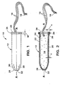
- the substance 14 When the substance 14 is a tampon, it normally will include a withdrawal string 16 extending outward therefrom.
- the withdrawal string 16 is used to remove the soiled tampon from a woman's vagina.
- the withdrawal string 16 can contain a knot 18 to assure that the withdrawal string 16 does not separate from the tampon 14.
- the hollow member 12 is in the shape of an elongated tube having a thin wall 20, and preferably, a circular cross-sectional profile.
- the wall 20 has a thickness "t" (see Fig. 2) of less than about .10 inches (about 2.54 mm), preferably less than about .03 inches (about .762 mm), and most preferably, less than about .02 inches (about 0.5 mm).
- the hollow member 12 is formed from at least two separate and distinct layers 22 and 24. Although only two layers 22 and 24 are depicted, the hollow member 12 could include three or more layers.
- the layers 22 and 24 can be formed from paper, paperboard, cardboard, plastic, thermoplastic films or any other suitable material. For purposes of this invention, a film coating on a paper layer is considered a two layer structure.
- the material which is used to form the inner layer 24 should be capable of stretching so that the inner layer 24 can be worked into a curl. It is important that the inner most layer 24 be capable of stretching more than the adjacent outer layer(s) because it will form the exterior surface of the fingergrip ring 34. This means that the inner most layer 24 will be formed on a larger diameter than the outer layer 22 and if it is not capable of stretching more than the outer layer 22 it will tear or deform and thereby produce a poorly shaped fingergrip ring.
- the inner layer(s) 24 should be capable of being stretched at least 4 percent, preferably at least 6 percent, and most preferably, at least 8 percent more than the outer layer 22. The amount of stretch can be in either the machine direction or in the cross direction depending on how the hollow, tubular member 12 is formed.
- the third function of the fingergrip ring 34 is to facilitate removal of the applicator 10 away from the user's skin or away from the vagina or other body cavity.
- the fingergrip ring 34 should have a sufficient height (h) so that this function can be performed without having the user's fingers slip off of the applicator 10.
- the fingergrip ring 34 provides a structure which will act as a stop for the tips of a user's thumb and finger(s) thereby allowing another finger of the user or another member to push the substance 14 out through the forward or first end 26 of the applicator 10.
- Fig. 4 an alternative "c curl” 44 is shown formed on the second end 28 of the applicator 10.
- the "c curl” 44 is obtained by curling both layers 22 and 24 approximately 270 degrees so that the distal end 38 of the tubular applicator 10 is brought into contact with the exterior surface of the first or outer layer 22.
- the two layers 22 and 24 are pressed during the formation process against the hollow, tubular member 12 such that no noticeable void area is present.
- This configuration has less open area than that shown in Fig. 3 but the curl 44 may still exhibit a limited void area.
- the fingergrip ring 34 may be formed with a lesser density than the material forming the tubular wall 20.
- each curl is comprised of tube wall material and usually some amount of void area 40.
- the tube wall is made from less expensive material and is typically multilayered, it has a thickness that is somewhat substantial. This gives the applicator sufficient strength to withstand the external pressures exerted on it.
- the outward extending fingergrip ring 34 must also have sufficient strength and height to function properly in use.
- each fingergrip ring 34 is comprised of a percentage of tube material and a complementary percentage of void area 40.
- the cross-sectional area of each fingergrip ring 34 is comprised of from between about 70 percent to about 95 percent of material and a complementary void area of between about 5 percent to about 30 percent.
- the cross-sectional area of each fingergrip ring 34 is comprised of from between about 80 percent to about 90 percent of material and a complementary void area of between about 10 percent to about 20 percent. This is a much greater percent of material in the fingergrip ring 34 than what is present in existing paper drinking cups where the amount of material present in the curl is between about 10 percent to about 20 percent and the void area is between about 80 percent to about 90 percent.
- the fingergrip ring 34 could be compressed such that it has a higher density than the tubular wall 20 from which it was formed. However, too much compression creates an unacceptable weak fingergrip ring 34. If the density at the top of the fingergrip ring 34 is increased too much, the fingergrip ring 34 can become brittle and a weak hinge point is thereby created. This is undesirable when using of the fingergrip ring 34 on a tampon applicator 10.
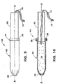
- the second member 68 or inner tube as it is sometimes referred to, is sized and configured to telescopically slide within the inner circumference of the first member 66.
- the second member 68 is preferably hollow although it does not have to be. As the second member 68 is pushed into the first member 66, the tampon 14 is expelled through the forward end 26 of the first member 66. After the tampon 14 is positioned in a woman's vagina, the applicator 64 is properly discarded.
- the tubular member 112 can be of any desired length. However, when used as a tampon applicator or as a medicinal applicator, the tubular member 112 should have a length of between about 1 inch to about 112 inches (about 25.4 mm to about 305 mm) and, preferably, between about 2 inches to about 6 inches (about 50.8 mm to about 152.7 mm). The most preferred length for a tampon applicator is about 3 inches (76.2 mm) and the most preferred length for a medicinal applicator, used to dispense a yeast infection medication, is about 6 inches (about 152.4 mm).
- the tubular member 112 can be constructed of any kind of material.
- the tubular member 112 should be constructed of paper, paperboard, cardboard, plastic, thermoplastic film or a combination of such materials.
- the tubular member 112 can also be formed as a laminate consisting of at least two separate layers. Each layer can be of a similar or different material. It is also anticipated that the outer layer of the tubular member 112 can be coated with a suitable coating to give it a certain characteristic. For example, the coating can be used to give the applicator a smooth, slippery, water-permeable or water-impermeable characteristic.
- tubular member 112 If two or more layers are utilized to form the tubular member 112, they can be bonded together by an adhesive, such as glue, by heat and/or pressure, by ultrasonics or by any other known means.
- an adhesive such as glue
- heat and/or pressure by ultrasonics or by any other known means.
- the first member 118 is designed to hold the tubular member 112 stationary.
- the first member 118 is depicted as an elongated member having a central, longitudinal axis A'--A'.
- the first member 118 includes a housing 122 having first and second spaced apart ends, 124 and 126 respectively.
- the housing 122 also has an elongated bore 128 formed therethrough which is coaxially aligned with the central, longitudinal axis A'--A'.
- the bore 128 extends between the first and second ends 124 and 126 of the housing 122.
- the bore 128 is sized and configured to be capable of receiving the tubular member 112.
- the first member 118 also includes a piston rod 134 which is partially situated in the bore 128.
- the piston rod 134 has a piston 136 attached to an end thereof which is located in the bore 128.
- the piston 136 includes a sleeve 138 having an outside diameter which is less than the inside diameter of the bore 128.
- the sleeve 138 contains an axially aligned slot 140 formed therethrough which enables the sleeve 138 to create a large enough diameter to produce a frictional fit with the tubular member 112.
- the piston 136 also has a conical surface 142 positioned inward from the sleeve 138 which acts as a stop for the tubular member 112.
- the second member 120 of the apparatus 110 is coaxially aligned along the central, longitudinal axis A'--A' of the first member 118 and is movably relative to the first end 124 of the first member 118.
- the second member 120 will be described as being aligned vertically below the first member 118, although the members 118 and 120 could be positioned at some other orientation if desired.
- first and second members, 118 and 120 respectively.
- the configuration needed on the second member 120 to form an outwardly directed curl on one end of the tubular member 112 will first be described.
- the configuration of the tooling needed to form an inwardly directed curl will be explained later.
- the insertion of the first end 156 of the pilot 154 into the tubular member 112 will assure that the wall 116 of the tubular member 112 cannot curl inward as the first and second members, 118 and 120 respectively, contact one another.
- the first end 156 of the pilot 154 can be inserted into the tubular member 112 any desired amount. However, the first end 156 of the pilot 154 should be inserted a distance of at least about 0.125 inches (about 3.17 mm) or more into the tubular member 112.
- the second member 120 also includes a sleeve 158 which surrounds the pilot 154.
- the sleeve 158 has an inside diameter which is in contact with the outer diameter of the pilot 154 except near the first end 156.
- the inside diameter of the sleeve 158 is spaced apart from the outer diameter of the first end 156 of the pilot 154. This clearance establishes an open area around the outer circumference of the tubular member 112 when the first and second members, 118 and 120 respectively, are moved into engagement.
- the open area provides a circumferential opening into which the outer end of the tubular member 112 can be curled outwardly relative to the central, longitudinal axis A'--A'.
- the inner diameter of the sleeve 158 cooperates with the outer periphery 132 of the shoulder 130 to form a curling chamber 160 when the second member 120 engages an end of the tubular member 112.
- the clearance between the inner diameter of the sleeve 158 and the outer periphery of the shoulder 130 is between about .001 inches to about .005 inches (about .02 mm to about .127 mm).
- the sleeve 158 and pilot 154 are stationary relative to one another and are designed to move axially together.
- the curling element 162 is inserted through and retained in two transversely oriented apertures 164 and 166 formed in the sleeve 158 as well as a transversely oriented aperture 68 formed through the first end 156 of the pilot 154.
- the curling element 162 can be spaced vertically away from the first end 156 of the pilot 154 by a distance of at least about 1/16 of an inch (about 1.58 mm). The exact distance which the curling element 162 is spaced away from the first end 156 of the pilot 154 can vary.
- the first and second members, 118 and 120 respectively, are similar to those depicted in Fig. 15 except that the curling element 162 is replaced by a curling element 178 having a non-uniform outer diameter.
- the curling element 178 is an elongated, cylindrical pin having two spaced apart grooves 180 and 182 formed therein. Each groove 180 and 182 has a smaller outside diameter than the outside diameter of the remainder of the curling element 178.
- the grooves 180 and 182 are situated between the first end 156 of the pilot 154 and the sleeve 158.
- the grooves 180 and 182 are vertically aligned with the circumferential end of the tubular member 112 as well as with the radially outwardly situated curling chamber 160.
- the tubular member 112 is shown having an outwardly extending, integral curl 184 formed on one end thereof.
- This curl 184 is obtained by using the tooling depicted in Fig. 17.
- the curl 184 is referred to as an "s" curl having a rounded corner 186 because of it's shape. It has been found that when the curling element 178 has a non-uniform outer diameter, that the rounded corners 186 are obtained.
- the apparatus 188 can include removal means for removing the tubular member 112 from the shaft 192.
- the removal means can be similar to that described and depicted above in Figs. 11 and 12 or it can be some other mechanism, such as a pneumatic, hydraulic, electrical or electro-mechanical mechanism.
Landscapes
- Engineering & Computer Science (AREA)
- Health & Medical Sciences (AREA)
- Mechanical Engineering (AREA)
- Vascular Medicine (AREA)
- Biomedical Technology (AREA)
- Heart & Thoracic Surgery (AREA)
- Epidemiology (AREA)
- Life Sciences & Earth Sciences (AREA)
- Animal Behavior & Ethology (AREA)
- General Health & Medical Sciences (AREA)
- Public Health (AREA)
- Veterinary Medicine (AREA)
- Absorbent Articles And Supports Therefor (AREA)
- Media Introduction/Drainage Providing Device (AREA)
- Coating Apparatus (AREA)
Applications Claiming Priority (5)
| Application Number | Priority Date | Filing Date | Title |
|---|---|---|---|
| US36620794A | 1994-12-29 | 1994-12-29 | |
| US08/366,074 US5614230A (en) | 1994-12-29 | 1994-12-29 | Apparatus for forming a curl on an end of a tubular member |
| US366207 | 1994-12-29 | ||
| US366074 | 1994-12-29 | ||
| EP95931555A EP0800374B2 (de) | 1994-12-29 | 1995-08-21 | Applikator zur aufnahme und abgabe einer substanz |
Related Parent Applications (1)
| Application Number | Title | Priority Date | Filing Date |
|---|---|---|---|
| EP95931555A Division EP0800374B2 (de) | 1994-12-29 | 1995-08-21 | Applikator zur aufnahme und abgabe einer substanz |
Publications (1)
| Publication Number | Publication Date |
|---|---|
| EP1060720A1 true EP1060720A1 (de) | 2000-12-20 |
Family
ID=27003216
Family Applications (2)
| Application Number | Title | Priority Date | Filing Date |
|---|---|---|---|
| EP95931555A Expired - Lifetime EP0800374B2 (de) | 1994-12-29 | 1995-08-21 | Applikator zur aufnahme und abgabe einer substanz |
| EP00119789A Withdrawn EP1060720A1 (de) | 1994-12-29 | 1995-08-21 | Vorrichtung zum formen eines rohrförmigen Körper |
Family Applications Before (1)
| Application Number | Title | Priority Date | Filing Date |
|---|---|---|---|
| EP95931555A Expired - Lifetime EP0800374B2 (de) | 1994-12-29 | 1995-08-21 | Applikator zur aufnahme und abgabe einer substanz |
Country Status (11)
| Country | Link |
|---|---|
| EP (2) | EP0800374B2 (de) |
| JP (1) | JP3844500B2 (de) |
| KR (1) | KR100390263B1 (de) |
| CN (1) | CN1175201A (de) |
| AU (1) | AU693937B2 (de) |
| BR (1) | BR9510421A (de) |
| CA (1) | CA2209337A1 (de) |
| CO (1) | CO4410308A1 (de) |
| DE (1) | DE69526368T3 (de) |
| MX (1) | MX9704797A (de) |
| WO (1) | WO1996020682A1 (de) |
Cited By (2)
| Publication number | Priority date | Publication date | Assignee | Title |
|---|---|---|---|---|
| WO2002102698A1 (es) * | 2001-06-15 | 2002-12-27 | Valls Roca Ramon | Procedimiento para la fabricacion de un tubo portabobinas de hilado, dispositivo para su realizacion, tubo portabobinas obtenido y modo de uso de dicho tubo portabobinas |
| US8852493B2 (en) | 2004-07-26 | 2014-10-07 | Stora Enso Oyj | Method of forming a mouth roll to a cup of plastic coated board and a cup made by the method |
Families Citing this family (8)
| Publication number | Priority date | Publication date | Assignee | Title |
|---|---|---|---|---|
| UY24128A1 (es) * | 1994-12-30 | 1995-03-25 | Mcneil Ppc Inc | Metodo para formar un aplicador de tampon de carton que tiene un extremo de agarre exteriormente enrollado. |
| US6450986B1 (en) * | 2000-06-19 | 2002-09-17 | Mcneil-Ppc, Inc. | Tampon applicator having outwardly flared rim |
| ATE322975T1 (de) | 2001-09-19 | 2006-04-15 | Procter & Gamble | Farbbedruckte mehrschichtstruktur, ein damit hergestellter absorbierender artikel und verfahren zu deren herstellung |
| US20040010220A1 (en) * | 2002-06-21 | 2004-01-15 | Playtex Products, Inc. | Tampon applicator with improved fingergrip and method of making same |
| CN100448419C (zh) * | 2003-10-31 | 2009-01-07 | 强生消费者公司 | 提供干净的手指插入的吸收棉塞 |
| US20060025743A1 (en) * | 2004-07-30 | 2006-02-02 | The Procter & Gamble Company | Absorbent article with color matched surfaces |
| US20060025742A1 (en) * | 2004-07-30 | 2006-02-02 | The Procter & Gamble Company | Absorbent article with color surfaces |
| WO2021114217A1 (zh) * | 2019-12-13 | 2021-06-17 | 吴静茹 | 纸质棉条导管的制造方法 |
Citations (7)
| Publication number | Priority date | Publication date | Assignee | Title |
|---|---|---|---|---|
| US1181965A (en) | 1914-11-02 | 1916-05-02 | George J Bohlman | Method of making paper cups. |
| US3065677A (en) | 1959-07-20 | 1962-11-27 | Paper Machinery Corp | Rim curling mechanism for containers |
| US3633469A (en) * | 1970-06-11 | 1972-01-11 | Phillips Petroleum Co | Rim curling apparatus and method |
| US4106396A (en) * | 1977-05-18 | 1978-08-15 | Phillips Petroleum Company | Apparatus for forming a container having a rolled rim |
| US4375969A (en) * | 1979-11-16 | 1983-03-08 | Boise Cascade Corporation | Method for forming a composite container including a reversely curled body member |
| US5184995A (en) * | 1990-12-31 | 1993-02-09 | James River Corporation Of Virginia | Containers and blanks with a curled edge and method of making same |
| EP0626254A2 (de) * | 1993-05-25 | 1994-11-30 | Sonoco Products Company | Verfahren und Vorrichtung zum Formen einer nach aussen gerollten Lippe auf einem zylindrischen Behälterkörper |
Family Cites Families (13)
| Publication number | Priority date | Publication date | Assignee | Title |
|---|---|---|---|---|
| CH186674A (de) * | 1936-08-08 | 1936-09-30 | Kobler & Co | Halte- und Ausstossvorrichtung für gepresste Wattepfropfen. |
| FR2080061A5 (en) * | 1970-02-23 | 1971-11-12 | Perrin Jacques | Vaginal tampon - contg particles of gelling material such as cellulose derivs |
| DE3121364A1 (de) † | 1981-05-29 | 1982-12-16 | Henkel KGaA, 4000 Düsseldorf | "applikator zum hygienischen einfuehren eines tampons" |
| EP0086869B1 (de) * | 1982-02-02 | 1986-06-11 | Maschinenfabrik Rissen GmbH | Verfahren zum Verarbeiten von Schaumthermoplastfolie |
| US5267953A (en) † | 1986-04-23 | 1993-12-07 | Kimberly-Clark Corporation | Curved tampon applicator and a process for forming the applicator and for assembling an absorbent tampon into said applicator |
| US4755164A (en) † | 1986-12-23 | 1988-07-05 | Hauni Richmond, Inc. | Method of and apparatus for making applicators of pledgets and the like |
| US4872933A (en) † | 1987-03-30 | 1989-10-10 | Kimberly-Clark Corporation | Method of forming rapidly disintegrating paper tubes |
| US5029749A (en) * | 1990-09-14 | 1991-07-09 | James River Corporation | Paper container and method of making the same |
| US5153971A (en) † | 1991-11-26 | 1992-10-13 | Kimberly-Clark Corporation | Method of forming a curved tampon |
| AU673812B2 (en) † | 1992-01-13 | 1996-11-28 | Tambrands, Inc. | Tampon applicator |
| DE4223286A1 (de) † | 1992-07-15 | 1994-04-07 | Johnson & Johnson Gmbh | Applikatorhülse |
| US5330421A (en) † | 1992-12-04 | 1994-07-19 | Tambrands Inc. | Tampon applicator |
| AU677612B2 (en) * | 1992-12-31 | 1997-05-01 | Mcneil-Ppc, Inc. | Environmentally friendly catamenial tampon assembly and method of construction |
-
1995
- 1995-08-21 CN CN95197666A patent/CN1175201A/zh active Pending
- 1995-08-21 AU AU34930/95A patent/AU693937B2/en not_active Ceased
- 1995-08-21 MX MX9704797A patent/MX9704797A/es active IP Right Grant
- 1995-08-21 CA CA002209337A patent/CA2209337A1/en not_active Abandoned
- 1995-08-21 KR KR1019970704482A patent/KR100390263B1/ko not_active Expired - Fee Related
- 1995-08-21 BR BR9510421A patent/BR9510421A/pt not_active IP Right Cessation
- 1995-08-21 EP EP95931555A patent/EP0800374B2/de not_active Expired - Lifetime
- 1995-08-21 DE DE69526368T patent/DE69526368T3/de not_active Expired - Fee Related
- 1995-08-21 JP JP52094596A patent/JP3844500B2/ja not_active Expired - Fee Related
- 1995-08-21 EP EP00119789A patent/EP1060720A1/de not_active Withdrawn
- 1995-08-21 WO PCT/US1995/010658 patent/WO1996020682A1/en not_active Ceased
- 1995-08-22 CO CO95037587A patent/CO4410308A1/es unknown
Patent Citations (7)
| Publication number | Priority date | Publication date | Assignee | Title |
|---|---|---|---|---|
| US1181965A (en) | 1914-11-02 | 1916-05-02 | George J Bohlman | Method of making paper cups. |
| US3065677A (en) | 1959-07-20 | 1962-11-27 | Paper Machinery Corp | Rim curling mechanism for containers |
| US3633469A (en) * | 1970-06-11 | 1972-01-11 | Phillips Petroleum Co | Rim curling apparatus and method |
| US4106396A (en) * | 1977-05-18 | 1978-08-15 | Phillips Petroleum Company | Apparatus for forming a container having a rolled rim |
| US4375969A (en) * | 1979-11-16 | 1983-03-08 | Boise Cascade Corporation | Method for forming a composite container including a reversely curled body member |
| US5184995A (en) * | 1990-12-31 | 1993-02-09 | James River Corporation Of Virginia | Containers and blanks with a curled edge and method of making same |
| EP0626254A2 (de) * | 1993-05-25 | 1994-11-30 | Sonoco Products Company | Verfahren und Vorrichtung zum Formen einer nach aussen gerollten Lippe auf einem zylindrischen Behälterkörper |
Cited By (5)
| Publication number | Priority date | Publication date | Assignee | Title |
|---|---|---|---|---|
| WO2002102698A1 (es) * | 2001-06-15 | 2002-12-27 | Valls Roca Ramon | Procedimiento para la fabricacion de un tubo portabobinas de hilado, dispositivo para su realizacion, tubo portabobinas obtenido y modo de uso de dicho tubo portabobinas |
| US7160236B2 (en) * | 2001-06-15 | 2007-01-09 | Klinsan Bcn S.L. | Process for production of a bobbin tube for yarn, device for embodiment of such process, bobbin tube obtained and mode of utilization of said bobbin tube |
| US7722518B2 (en) | 2001-06-15 | 2010-05-25 | Klinsan Bcn S.L. | Process for production of a bobbin tube for yarn, device for embodiment of such process, bobbin tube obtained and mode of utilisation of said bobbin tube |
| US8123157B2 (en) | 2001-06-15 | 2012-02-28 | Klinsan Bcn S.L. | Process for production of a bobbin tube for yarn, device for embodiment of such process, bobbin tube obtained and mode of utilisation of said bobbin tube |
| US8852493B2 (en) | 2004-07-26 | 2014-10-07 | Stora Enso Oyj | Method of forming a mouth roll to a cup of plastic coated board and a cup made by the method |
Also Published As
| Publication number | Publication date |
|---|---|
| JPH10511585A (ja) | 1998-11-10 |
| AU693937B2 (en) | 1998-07-09 |
| KR100390263B1 (ko) | 2003-08-19 |
| EP0800374B2 (de) | 2005-08-10 |
| CN1175201A (zh) | 1998-03-04 |
| MX9704797A (es) | 1997-10-31 |
| DE69526368D1 (de) | 2002-05-16 |
| WO1996020682A1 (en) | 1996-07-11 |
| EP0800374A1 (de) | 1997-10-15 |
| DE69526368T2 (de) | 2002-11-28 |
| AU3493095A (en) | 1996-07-24 |
| DE69526368T3 (de) | 2006-03-30 |
| BR9510421A (pt) | 1999-01-12 |
| CA2209337A1 (en) | 1996-07-11 |
| JP3844500B2 (ja) | 2006-11-15 |
| CO4410308A1 (es) | 1997-01-09 |
| EP0800374B1 (de) | 2002-04-10 |
Similar Documents
| Publication | Publication Date | Title |
|---|---|---|
| US5683358A (en) | Applicator for holding and dispensing a substance | |
| US5571540A (en) | Apparatus for crimping, pleating and forming a tip on a hollow tube | |
| CA2212011C (en) | Tampon applicator | |
| AU753096B2 (en) | Flexible applicator for inserting an article into a mammalian body cavity | |
| US6264626B1 (en) | Paperboard applicators having improved gripping features | |
| US4650459A (en) | Convolutely wound paper tampon tube | |
| WO1996005795A2 (en) | Tampon applicator | |
| JPH03106365A (ja) | タンポン | |
| US5614230A (en) | Apparatus for forming a curl on an end of a tubular member | |
| EP0800374B1 (de) | Applikator zur aufnahme und abgabe einer substanz | |
| JP2009090144A (ja) | タンポンアプリケータの外筒 | |
| CA2199293A1 (en) | Apparatus and method of reducing the force to expel a tampon from a tampon applicator and the applicator itself | |
| EP0777452B1 (de) | Tamponapplikator mit einer halbkugelförmig geformten gefalteten spitze | |
| EP0777453B1 (de) | Tamponapplikator mit einer verbesserten gefalteten spitze | |
| WO2026075931A1 (en) | Method for forming a cellulosic tampon applicator | |
| MXPA97001721A (en) | Apparatus and method to reduce the force to eject a plug from a plug applicator and the applicator my |
Legal Events
| Date | Code | Title | Description |
|---|---|---|---|
| PUAI | Public reference made under article 153(3) epc to a published international application that has entered the european phase |
Free format text: ORIGINAL CODE: 0009012 |
|
| 17P | Request for examination filed |
Effective date: 20000911 |
|
| AC | Divisional application: reference to earlier application |
Ref document number: 800374 Country of ref document: EP |
|
| AK | Designated contracting states |
Kind code of ref document: A1 Designated state(s): BE DE ES FR GB IT NL SE |
|
| K1C1 | Correction of patent application (title page) published |
Effective date: 20001220 |
|
| 17Q | First examination report despatched |
Effective date: 20010702 |
|
| AKX | Designation fees paid |
Free format text: BE DE ES FR GB IT NL SE |
|
| GRAG | Despatch of communication of intention to grant |
Free format text: ORIGINAL CODE: EPIDOS AGRA |
|
| GRAG | Despatch of communication of intention to grant |
Free format text: ORIGINAL CODE: EPIDOS AGRA |
|
| GRAH | Despatch of communication of intention to grant a patent |
Free format text: ORIGINAL CODE: EPIDOS IGRA |
|
| RIN1 | Information on inventor provided before grant (corrected) |
Inventor name: WEYENBERG, JEFFREY MICHAEL Inventor name: RASMUSSEN, NOEL JOHN Inventor name: KRUEGER, ALLEN JAMES Inventor name: NIELSEN, STEVEN JAMES |
|
| STAA | Information on the status of an ep patent application or granted ep patent |
Free format text: STATUS: THE APPLICATION IS DEEMED TO BE WITHDRAWN |
|
| 18D | Application deemed to be withdrawn |
Effective date: 20021102 |