EP1060865A2 - Procédé et appareil pour ouvrir ou fermer les moules d'une machine de traitement de matière plastique - Google Patents
Procédé et appareil pour ouvrir ou fermer les moules d'une machine de traitement de matière plastique Download PDFInfo
- Publication number
- EP1060865A2 EP1060865A2 EP00106773A EP00106773A EP1060865A2 EP 1060865 A2 EP1060865 A2 EP 1060865A2 EP 00106773 A EP00106773 A EP 00106773A EP 00106773 A EP00106773 A EP 00106773A EP 1060865 A2 EP1060865 A2 EP 1060865A2
- Authority
- EP
- European Patent Office
- Prior art keywords
- blow
- platen
- carriage
- yokes
- mold halves
- Prior art date
- Legal status (The legal status is an assumption and is not a legal conclusion. Google has not performed a legal analysis and makes no representation as to the accuracy of the status listed.)
- Withdrawn
Links
Images
Classifications
-
- B—PERFORMING OPERATIONS; TRANSPORTING
- B29—WORKING OF PLASTICS; WORKING OF SUBSTANCES IN A PLASTIC STATE IN GENERAL
- B29C—SHAPING OR JOINING OF PLASTICS; SHAPING OF MATERIAL IN A PLASTIC STATE, NOT OTHERWISE PROVIDED FOR; AFTER-TREATMENT OF THE SHAPED PRODUCTS, e.g. REPAIRING
- B29C49/00—Blow-moulding, i.e. blowing a preform or parison to a desired shape within a mould; Apparatus therefor
- B29C49/42—Component parts, details or accessories; Auxiliary operations
- B29C49/56—Opening, closing or clamping means
- B29C49/5607—Electrically operated, e.g. the closing or opening is done with an electrical motor direct drive
-
- B—PERFORMING OPERATIONS; TRANSPORTING
- B29—WORKING OF PLASTICS; WORKING OF SUBSTANCES IN A PLASTIC STATE IN GENERAL
- B29C—SHAPING OR JOINING OF PLASTICS; SHAPING OF MATERIAL IN A PLASTIC STATE, NOT OTHERWISE PROVIDED FOR; AFTER-TREATMENT OF THE SHAPED PRODUCTS, e.g. REPAIRING
- B29C49/00—Blow-moulding, i.e. blowing a preform or parison to a desired shape within a mould; Apparatus therefor
- B29C49/02—Combined blow-moulding and manufacture of the preform or the parison
- B29C49/04—Extrusion blow-moulding
-
- B—PERFORMING OPERATIONS; TRANSPORTING
- B29—WORKING OF PLASTICS; WORKING OF SUBSTANCES IN A PLASTIC STATE IN GENERAL
- B29C—SHAPING OR JOINING OF PLASTICS; SHAPING OF MATERIAL IN A PLASTIC STATE, NOT OTHERWISE PROVIDED FOR; AFTER-TREATMENT OF THE SHAPED PRODUCTS, e.g. REPAIRING
- B29C49/00—Blow-moulding, i.e. blowing a preform or parison to a desired shape within a mould; Apparatus therefor
- B29C49/28—Blow-moulding apparatus
- B29C49/30—Blow-moulding apparatus having movable moulds or mould parts
- B29C49/32—Blow-moulding apparatus having movable moulds or mould parts moving "to and fro"
Definitions
- the invention relates to a method and a device for closing and opening the molds of a two-station plastic processing machine, in particular a blow molding machine
- the tools in the two stations each include two blow mold halves with platen and the outer blow mold halves by means of drive means with yokes of the outer Mold mounting plates are in operative connection, can be moved horizontally and the blow mold halves from an open position to receive a tubular preform below an extrusion head in a closed position be moved.
- DE 197 47 698 A1 discloses a blow molding machine with tie bar-less Base frame for the production of blow molded plastic hollow body known in the the blow mold halves for receiving the tubular preform by means of a Transport device are horizontally displaceable, which to the Mold mounting plates or to the assigned ones, which support the mold mounting plates Pillow blocks attack.
- the transport device comprises two separate Drive units, each outer platen with one of these drive units Is provided.
- a two-station machine is a common middle next to two outer platen Mold mounting plate is provided, which belongs to both stations, being on both Sides of each blow mold half is stretched. By the influence of the two independently driven outer platen or their bearing blocks this medium platen is free on the Base frame shifted.
- the object of the invention based on a method and an apparatus of the type mentioned to create, with a movement of the blow mold halves of the tools between an open position for receiving a tubular preform and one Closing position or blowing position is easy and variable to accomplish.
- the basic idea of the invention is that the inner platen the blow mold halves of the two tools with a separate and preferably common holding means are arranged firmly on a carriage.
- the Blow mold halves are arranged diametrically to each other. This sled is lengthways the hose take-up position on guides can be moved horizontally.
- the outer Mold mounting plates on the other hand, can be moved independently of the slide, for this purpose they are preferably provided with separate drive means. So can the tools in a simple and variable way between an open position and a closed position below the hose receiving station, a blowing station or waiting position and a return movement to the hose receiving position, which is also the hose removal position.
- the proposed solution ensures that both the outer and the inner blow mold halves of the tools are moved independently of one another can.
- the slide is used to move the inner blow mold halves as well advantageously for moving the closed tool over larger ones Stretches between hose take-up position or blow station or waiting station, while by means of the independently movable outer platen or outer blow mold halves a quick opening and closing of the respective Tool is guaranteed below the hose receiving station.
- a plastic preform is placed in the open one Tool lowered and the lower end of the hose on a blow mandrel device lowered and kept spread. Then the blow mold halves moved together and closed according to the method described above. To ensure that the respective blow mandrel device is always below the preform is placed, the blow mandrel device is synchronously counter the carriage movement on the carriage frame. This will be preferred thereby achieved by the drive means for the outer platen also in operative connection with those below each tool arranged blow mandrel devices stand. In doing so, a preferred Embodiment both the mandrel devices and the respective outer Mold platen driven by a common drive means.
- a motor for this is direct or with a Gearbox connected via a threaded spindle, which is in axial extension both a nut for the blow mandrel device and for the respective outer Has platen.
- the carriage preferably has a separate drive unit in the form of a Motors on.
- the motors can be of any type, for example hydraulically or pneumatically or electrically driven motors.
- the sled motor also drives a spindle with a fixed one
- the nut is operatively connected to generate the linear movement of the slide.
- the slide must be between the open position and the closed position preferably only half the distance compared to the corresponding outer one Put back the platen. This is achieved through accordingly different pitches of the spindles with the same engine revolutions. Alternatively is the procedure over differently large distances also by adapted Engine speeds possible.
- any other types of known gears are conceivable, for example a pinion, which is a linear movement due to its meshing engagement with a rack accomplished.
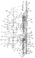
- the single figure is a two-station blow molding machine with one Closing unit 1 for the molds of two tools 2, 3, with a preform hose providing extrusion head 4 and two below the tools arranged blow mandrel devices 5, 6 shown.
- the first tool 2 comprises the two blow mold halves 7, 8, the second tool 3 the two blow mold halves 9, 10.
- the blow mold halves 7, 8, 9 and 10 are detachable on mold mounting plates 11 to 14 attached.
- Each platen has a yoke 15, 17 or connected to a holding means 16.
- the yokes 15 and 17 are the outer platen on the frame of a carriage 18 horizontally movable, while the inner platen 12, 13 on a fixed the sled frame 18 arranged column 19 are connected to this.
- the yokes 15 and 17 of the two outer platen 11 and 14 are provided with separate drive means 20 and 21. For this, one is through a motor 22 or 23 driven and arranged in bearings 24 or 25 Spindle 26 and 27 provided which runs in a nut 28 and 29 by a Support arm 30 or 31 is added. The support arm 30 or 31 engages Guide element 32 or 33 on which a holding arm 34 or 35 of the yoke 15 or 17 is attached.
- the carriage 18 is horizontal by means of rollers 44 to 46 on guide rails 47 movable along the extrusion head 4.
- the carriage 18 has an independent Drive unit 48 in the form of a spindle 50 driven by a motor 49 on, which is in operative connection with a firmly anchored nut 51 and the rotation the spindle 50 is converted into a longitudinal movement of the slide frame.
- first stage with the first tool 2 and shown closed tool 3 and a second stage with closed and moved first tool 2, here dash-dotted in the end position featured.
- an opened first tool 2 is located below of the extrusion head 4, a preform (not shown) is inserted, which is placed on the mandrel 40 of the blow mandrel device 5. Then will the tool 2 closed by the carriage 18 and thus placed firmly inner mold mounting plate 12 or inner blow mold half 7 in this embodiment half an opening travel 1 ⁇ 2 x. For compensation the carriage path, the outer platen 11 is then around the entire opening path x in the opposite direction relative to the slide or the blow mandrel device 5 is moved half the opening distance.
- the first tool 2 is removed from the hose receiving position by moving the carriage 18 to a blowing station or waiting position brought.
- the maximum transport route is labeled y.
- the second tool 3 is simultaneously driven into the hose receiving station, which at the same time the item removal station is. By moving the second outer platen 14, the tool 3 is opened and the finished plastic part can be removed.
Landscapes
- Engineering & Computer Science (AREA)
- Manufacturing & Machinery (AREA)
- Mechanical Engineering (AREA)
- Moulds For Moulding Plastics Or The Like (AREA)
- Blow-Moulding Or Thermoforming Of Plastics Or The Like (AREA)
Applications Claiming Priority (2)
| Application Number | Priority Date | Filing Date | Title |
|---|---|---|---|
| DE19927138A DE19927138C2 (de) | 1999-06-15 | 1999-06-15 | Verfahren und Vorrichtung zum Schließen und Öffnen der Formwerkzeuge einer Kunststoffverarbeitungsmaschine |
| DE19927138 | 1999-06-15 |
Publications (2)
| Publication Number | Publication Date |
|---|---|
| EP1060865A2 true EP1060865A2 (fr) | 2000-12-20 |
| EP1060865A3 EP1060865A3 (fr) | 2002-08-28 |
Family
ID=7911222
Family Applications (1)
| Application Number | Title | Priority Date | Filing Date |
|---|---|---|---|
| EP00106773A Withdrawn EP1060865A3 (fr) | 1999-06-15 | 2000-03-30 | Procédé et appareil pour ouvrir ou fermer les moules d'une machine de traitement de matière plastique |
Country Status (3)
| Country | Link |
|---|---|
| US (1) | US6514452B1 (fr) |
| EP (1) | EP1060865A3 (fr) |
| DE (1) | DE19927138C2 (fr) |
Cited By (6)
| Publication number | Priority date | Publication date | Assignee | Title |
|---|---|---|---|---|
| EP1306193A3 (fr) * | 2001-10-24 | 2003-10-15 | Magic MP S.p.A. | Dispositif de moulage par soufflage de récipients en plastique ayant dispositifs électriques d'actionnement |
| US7210755B2 (en) | 2000-06-16 | 2007-05-01 | Canon Kabushiki Kaisha | Solid semiconductor element, ink tank, ink jet recording apparatus provided with ink tank, liquid information acquiring method and liquid physical property change discriminating method |
| EP1884342A3 (fr) * | 2006-08-03 | 2008-08-06 | BEKUM Maschinenfabriken GmbH | Dispositif et procédé destinés à la fabrication de corps creux à partir de matières synthétiques thermoplastiques dans un procédé de soufflage |
| WO2013007421A1 (fr) * | 2011-07-13 | 2013-01-17 | Krones Ag | Machine de moulage par soufflage pour récipients en plastique |
| US9321229B2 (en) | 2011-07-13 | 2016-04-26 | Krones Ag | One-star system for feeding and discharging containers for processing machines |
| US9463591B2 (en) | 2011-04-13 | 2016-10-11 | Krones Ag | Container treatment machine and method of treating containers |
Families Citing this family (9)
| Publication number | Priority date | Publication date | Assignee | Title |
|---|---|---|---|---|
| ITBO20020618A1 (it) * | 2002-09-30 | 2004-04-01 | Sacmi | Macchina a stampo singolo per il colaggio in pressione |
| US7850443B2 (en) * | 2007-11-23 | 2010-12-14 | Dme Company Llc | Apparatus for injection molding |
| CN201357535Y (zh) * | 2009-03-13 | 2009-12-09 | 苏州红枫风电模具有限公司 | 用于大型组合式模具的可调整的对齐装置 |
| WO2011127524A1 (fr) * | 2010-04-12 | 2011-10-20 | Pro Technical Plastic Manufacturing Solutions Pty Ltd | Machine de moulage par soufflage et procédé de moulage par soufflage |
| DE102012100161A1 (de) | 2012-01-10 | 2013-07-11 | Extraplast Maschinen Gmbh | Blasformsystem sowie Verfahren zur Blasformung von Hohlkörpern |
| DE102012100156A1 (de) | 2012-01-10 | 2013-07-11 | Extraplast Maschinen Gmbh | Blasformsystem sowie Verfahren zur Blasformung von Hohlkörpern |
| US10471644B2 (en) * | 2017-11-28 | 2019-11-12 | Weiler Engineering, Inc. | Blow molding apparatus |
| WO2020073041A2 (fr) * | 2018-10-05 | 2020-04-09 | Uniloy, Inc. | Appareil et système de moulage par soufflage |
| WO2025223845A1 (fr) | 2024-04-22 | 2025-10-30 | S.T. Soffiaggio Tecnica Srl | Unité de fermeture à la presse, en particulier pour une machine de moulage par soufflage |
Family Cites Families (11)
| Publication number | Priority date | Publication date | Assignee | Title |
|---|---|---|---|---|
| US3069722A (en) * | 1959-05-27 | 1962-12-25 | Kato Takeo | Blow moulder |
| US5145353A (en) * | 1991-06-10 | 1992-09-08 | The Dow Chemical Company | Dual action molding press |
| DE9308467U1 (de) * | 1992-05-15 | 1993-08-19 | Mauser-Werke GmbH, 50321 Brühl | Blasformmaschine |
| DE9206649U1 (de) * | 1992-05-15 | 1993-09-16 | Mauser-Werke GmbH, 50321 Brühl | Blasformmaschine |
| US5551862A (en) * | 1994-06-06 | 1996-09-03 | Wilmington Machinery | Dual parison stacked clamp blow molding apparatus |
| US5753153A (en) * | 1996-01-02 | 1998-05-19 | Husky Injection Molding Systems Ltd. | Method for mold clamping units |
| IT1282432B1 (it) * | 1995-09-27 | 1998-03-23 | Sipa Spa | Impianto perfezionato per la produzione di contenitori in resina termoplastica |
| US5681596A (en) * | 1996-03-06 | 1997-10-28 | Wilmington Machinery, Inc. | Dual parison stacked clamp blow molding apparatus |
| DE29619781U1 (de) | 1996-11-15 | 1997-01-02 | Mauser-Werke GmbH, 50321 Brühl | Blasformmaschine |
| US6089852A (en) * | 1998-04-22 | 2000-07-18 | Tradesco Mold Limited | Mold centering arrangement for injection molding apparatus |
| DE19912116A1 (de) * | 1999-03-18 | 2000-09-21 | Kautex Maschinenbau Gmbh | Verfahren und Vorrichtung zum Herstellen von Hohlkörpern aus thermoplastischem Kunststoff |
-
1999
- 1999-06-15 DE DE19927138A patent/DE19927138C2/de not_active Expired - Fee Related
-
2000
- 2000-03-30 EP EP00106773A patent/EP1060865A3/fr not_active Withdrawn
- 2000-06-15 US US09/594,939 patent/US6514452B1/en not_active Expired - Fee Related
Cited By (8)
| Publication number | Priority date | Publication date | Assignee | Title |
|---|---|---|---|---|
| US7210755B2 (en) | 2000-06-16 | 2007-05-01 | Canon Kabushiki Kaisha | Solid semiconductor element, ink tank, ink jet recording apparatus provided with ink tank, liquid information acquiring method and liquid physical property change discriminating method |
| EP1306193A3 (fr) * | 2001-10-24 | 2003-10-15 | Magic MP S.p.A. | Dispositif de moulage par soufflage de récipients en plastique ayant dispositifs électriques d'actionnement |
| US6884059B2 (en) | 2001-10-24 | 2005-04-26 | Magic Mp S.P.A. | Electrically actuated blow-moulding machine |
| EP1884342A3 (fr) * | 2006-08-03 | 2008-08-06 | BEKUM Maschinenfabriken GmbH | Dispositif et procédé destinés à la fabrication de corps creux à partir de matières synthétiques thermoplastiques dans un procédé de soufflage |
| US9463591B2 (en) | 2011-04-13 | 2016-10-11 | Krones Ag | Container treatment machine and method of treating containers |
| WO2013007421A1 (fr) * | 2011-07-13 | 2013-01-17 | Krones Ag | Machine de moulage par soufflage pour récipients en plastique |
| US8939749B2 (en) | 2011-07-13 | 2015-01-27 | Krones Ag | Blow-molding machine for plastic containers |
| US9321229B2 (en) | 2011-07-13 | 2016-04-26 | Krones Ag | One-star system for feeding and discharging containers for processing machines |
Also Published As
| Publication number | Publication date |
|---|---|
| DE19927138A1 (de) | 2001-01-04 |
| DE19927138C2 (de) | 2002-02-28 |
| US6514452B1 (en) | 2003-02-04 |
| EP1060865A3 (fr) | 2002-08-28 |
Similar Documents
| Publication | Publication Date | Title |
|---|---|---|
| DE19747698C2 (de) | Blasformmaschine | |
| DE19927138C2 (de) | Verfahren und Vorrichtung zum Schließen und Öffnen der Formwerkzeuge einer Kunststoffverarbeitungsmaschine | |
| EP1673208B1 (fr) | Machine de moulage par injection horizontale pourvue d'un dispositif tournant | |
| EP0249703A2 (fr) | Machine à injecter à au moins deux unités de plastification et d'injection | |
| DE69222188T2 (de) | Vorrichtung und verfahren zur herstellung von rohren und schläuchen | |
| DE3720214A1 (de) | Spritzgiessmaschine | |
| DE3529775C2 (fr) | ||
| DE4223314A1 (de) | Einrichtung zum Schließen und Öffnen von Formen | |
| DE3036333C2 (de) | Vorrichtung zur Entnahme von Werkstücken an einer Druck- oder Spritzgießmaschine | |
| DE19922684C2 (de) | Blasformmaschine für das abfallarme Blasen | |
| WO2002057062A1 (fr) | Dispositif d'ejection pour machine a mouler | |
| WO2006084668A1 (fr) | Machine de moulage par injection pour l'usinage de matieres plastiques | |
| DE102007049655B4 (de) | Korrugatoreinrichtung mit Entformungseinrichtung | |
| DE2161247C3 (de) | Vorrichtung zum Herstellen von Hohlkörpern | |
| EP0734837A1 (fr) | Dispositif pour transporter une paraison d'une filière annulaire au moule de soufflage d'une machine de moulage par soufflage | |
| DE19503386C2 (de) | Handlinggerät für eine Werkzeugmaschine, insbesondere eine Spritzgießmaschine | |
| AT411522B (de) | Spritzgiesseinrichtung | |
| EP0887173A1 (fr) | Procédé et dispositif pour le moulage par soufflage de corps creux cintrés en matière thermoplastique | |
| EP1048435A1 (fr) | Procédé et appareil de moulage par injection-soufflage | |
| DE102006006244B4 (de) | Blasmaschine mit zwei Schließeinheiten | |
| DE102007061186A1 (de) | Biegevorrichtung, insbesondere für rohrförmige Bauteile | |
| EP4292789A1 (fr) | Moule de coulée sous pression | |
| DE19925325A1 (de) | Schließeinheit für eine Maschine für die Verarbeitung von spritzgießfähigem Material | |
| DE3619595A1 (de) | Verfahren und vorrichtung zum spritzen von leitfaehigem und isolierendem kunststoff auf einer zweifarben-spritzgussmaschine | |
| DE10317711A1 (de) | Formvorrichtung |
Legal Events
| Date | Code | Title | Description |
|---|---|---|---|
| PUAI | Public reference made under article 153(3) epc to a published international application that has entered the european phase |
Free format text: ORIGINAL CODE: 0009012 |
|
| AK | Designated contracting states |
Kind code of ref document: A2 Designated state(s): AT BE CH CY DE DK ES FI FR GB GR IE IT LI LU MC NL PT SE |
|
| AX | Request for extension of the european patent |
Free format text: AL;LT;LV;MK;RO;SI |
|
| RAP1 | Party data changed (applicant data changed or rights of an application transferred) |
Owner name: SIG KAUTEX GMBH & CO.KG |
|
| PUAL | Search report despatched |
Free format text: ORIGINAL CODE: 0009013 |
|
| AK | Designated contracting states |
Kind code of ref document: A3 Designated state(s): AT BE CH CY DE DK ES FI FR GB GR IE IT LI LU MC NL PT SE |
|
| AX | Request for extension of the european patent |
Free format text: AL;LT;LV;MK;RO;SI |
|
| 17P | Request for examination filed |
Effective date: 20030220 |
|
| 17Q | First examination report despatched |
Effective date: 20030318 |
|
| AKX | Designation fees paid |
Designated state(s): AT BE CH CY DE DK ES FI FR GB GR IE IT LI LU MC NL PT SE |
|
| GRAP | Despatch of communication of intention to grant a patent |
Free format text: ORIGINAL CODE: EPIDOSNIGR1 |
|
| STAA | Information on the status of an ep patent application or granted ep patent |
Free format text: STATUS: THE APPLICATION IS DEEMED TO BE WITHDRAWN |
|
| 18D | Application deemed to be withdrawn |
Effective date: 20040210 |