EP1060891B1 - Aufzeichnungskopf und Aufzeichnungsgerät - Google Patents
Aufzeichnungskopf und Aufzeichnungsgerät Download PDFInfo
- Publication number
- EP1060891B1 EP1060891B1 EP00304914A EP00304914A EP1060891B1 EP 1060891 B1 EP1060891 B1 EP 1060891B1 EP 00304914 A EP00304914 A EP 00304914A EP 00304914 A EP00304914 A EP 00304914A EP 1060891 B1 EP1060891 B1 EP 1060891B1
- Authority
- EP
- European Patent Office
- Prior art keywords
- voltage
- recording
- circuit
- recording head
- generating circuit
- Prior art date
- Legal status (The legal status is an assumption and is not a legal conclusion. Google has not performed a legal analysis and makes no representation as to the accuracy of the status listed.)
- Expired - Lifetime
Links
- 238000010586 diagram Methods 0.000 description 16
- 238000000034 method Methods 0.000 description 14
- 239000007788 liquid Substances 0.000 description 13
- 238000007639 printing Methods 0.000 description 12
- 238000007599 discharging Methods 0.000 description 9
- 238000010438 heat treatment Methods 0.000 description 7
- 239000000463 material Substances 0.000 description 6
- 239000004033 plastic Substances 0.000 description 6
- 229920003023 plastic Polymers 0.000 description 6
- 238000007781 pre-processing Methods 0.000 description 6
- XUIMIQQOPSSXEZ-UHFFFAOYSA-N Silicon Chemical compound [Si] XUIMIQQOPSSXEZ-UHFFFAOYSA-N 0.000 description 3
- XSQUKJJJFZCRTK-UHFFFAOYSA-N Urea Chemical compound NC(N)=O XSQUKJJJFZCRTK-UHFFFAOYSA-N 0.000 description 3
- 229910052782 aluminium Inorganic materials 0.000 description 3
- XAGFODPZIPBFFR-UHFFFAOYSA-N aluminium Chemical compound [Al] XAGFODPZIPBFFR-UHFFFAOYSA-N 0.000 description 3
- 230000015572 biosynthetic process Effects 0.000 description 3
- 230000005587 bubbling Effects 0.000 description 3
- 239000000919 ceramic Substances 0.000 description 3
- 239000000428 dust Substances 0.000 description 3
- 238000004519 manufacturing process Methods 0.000 description 3
- 229910052751 metal Inorganic materials 0.000 description 3
- 239000002184 metal Substances 0.000 description 3
- 239000002245 particle Substances 0.000 description 3
- 238000012545 processing Methods 0.000 description 3
- 229910052710 silicon Inorganic materials 0.000 description 3
- 239000010703 silicon Substances 0.000 description 3
- 238000012421 spiking Methods 0.000 description 3
- 239000000126 substance Substances 0.000 description 3
- 239000000758 substrate Substances 0.000 description 3
- 239000004753 textile Substances 0.000 description 3
- 229910010293 ceramic material Inorganic materials 0.000 description 2
- 230000000694 effects Effects 0.000 description 2
- 230000005611 electricity Effects 0.000 description 2
- 238000005516 engineering process Methods 0.000 description 2
- 239000011521 glass Substances 0.000 description 2
- 239000010985 leather Substances 0.000 description 2
- 230000007257 malfunction Effects 0.000 description 2
- 238000012805 post-processing Methods 0.000 description 2
- 239000011347 resin Substances 0.000 description 2
- 229920005989 resin Polymers 0.000 description 2
- 230000000630 rising effect Effects 0.000 description 2
- 230000000087 stabilizing effect Effects 0.000 description 2
- 230000003068 static effect Effects 0.000 description 2
- UMGDCJDMYOKAJW-UHFFFAOYSA-N thiourea Chemical compound NC(N)=S UMGDCJDMYOKAJW-UHFFFAOYSA-N 0.000 description 2
- -1 thread Substances 0.000 description 2
- 239000002023 wood Substances 0.000 description 2
- 235000017166 Bambusa arundinacea Nutrition 0.000 description 1
- 235000017491 Bambusa tulda Nutrition 0.000 description 1
- 241001330002 Bambuseae Species 0.000 description 1
- RYGMFSIKBFXOCR-UHFFFAOYSA-N Copper Chemical compound [Cu] RYGMFSIKBFXOCR-UHFFFAOYSA-N 0.000 description 1
- CBENFWSGALASAD-UHFFFAOYSA-N Ozone Chemical compound [O-][O+]=O CBENFWSGALASAD-UHFFFAOYSA-N 0.000 description 1
- 235000015334 Phyllostachys viridis Nutrition 0.000 description 1
- 230000002745 absorbent Effects 0.000 description 1
- 239000002250 absorbent Substances 0.000 description 1
- 230000003213 activating effect Effects 0.000 description 1
- 239000000853 adhesive Substances 0.000 description 1
- 230000001070 adhesive effect Effects 0.000 description 1
- 239000011425 bamboo Substances 0.000 description 1
- 230000000740 bleeding effect Effects 0.000 description 1
- 238000009835 boiling Methods 0.000 description 1
- 239000003990 capacitor Substances 0.000 description 1
- 239000004202 carbamide Substances 0.000 description 1
- 238000006243 chemical reaction Methods 0.000 description 1
- 239000003795 chemical substances by application Substances 0.000 description 1
- 238000004891 communication Methods 0.000 description 1
- 229910052802 copper Inorganic materials 0.000 description 1
- 239000010949 copper Substances 0.000 description 1
- 230000006866 deterioration Effects 0.000 description 1
- 239000004744 fabric Substances 0.000 description 1
- 239000000835 fiber Substances 0.000 description 1
- 238000002347 injection Methods 0.000 description 1
- 239000007924 injection Substances 0.000 description 1
- 230000001678 irradiating effect Effects 0.000 description 1
- 238000012423 maintenance Methods 0.000 description 1
- 239000007769 metal material Substances 0.000 description 1
- 150000002739 metals Chemical class 0.000 description 1
- 230000002093 peripheral effect Effects 0.000 description 1
- 239000011120 plywood Substances 0.000 description 1
- 229920002492 poly(sulfone) Polymers 0.000 description 1
- 230000002265 prevention Effects 0.000 description 1
- 230000005855 radiation Effects 0.000 description 1
- 150000003839 salts Chemical class 0.000 description 1
- 239000004065 semiconductor Substances 0.000 description 1
- 229920001059 synthetic polymer Polymers 0.000 description 1
- 230000002463 transducing effect Effects 0.000 description 1
- 238000012546 transfer Methods 0.000 description 1
- 238000011144 upstream manufacturing Methods 0.000 description 1
Images







Classifications
-
- B—PERFORMING OPERATIONS; TRANSPORTING
- B41—PRINTING; LINING MACHINES; TYPEWRITERS; STAMPS
- B41J—TYPEWRITERS; SELECTIVE PRINTING MECHANISMS, i.e. MECHANISMS PRINTING OTHERWISE THAN FROM A FORME; CORRECTION OF TYPOGRAPHICAL ERRORS
- B41J2/00—Typewriters or selective printing mechanisms characterised by the printing or marking process for which they are designed
- B41J2/005—Typewriters or selective printing mechanisms characterised by the printing or marking process for which they are designed characterised by bringing liquid or particles selectively into contact with a printing material
- B41J2/01—Ink jet
-
- B—PERFORMING OPERATIONS; TRANSPORTING
- B41—PRINTING; LINING MACHINES; TYPEWRITERS; STAMPS
- B41J—TYPEWRITERS; SELECTIVE PRINTING MECHANISMS, i.e. MECHANISMS PRINTING OTHERWISE THAN FROM A FORME; CORRECTION OF TYPOGRAPHICAL ERRORS
- B41J2/00—Typewriters or selective printing mechanisms characterised by the printing or marking process for which they are designed
- B41J2/005—Typewriters or selective printing mechanisms characterised by the printing or marking process for which they are designed characterised by bringing liquid or particles selectively into contact with a printing material
- B41J2/01—Ink jet
- B41J2/015—Ink jet characterised by the jet generation process
- B41J2/04—Ink jet characterised by the jet generation process generating single droplets or particles on demand
- B41J2/045—Ink jet characterised by the jet generation process generating single droplets or particles on demand by pressure, e.g. electromechanical transducers
- B41J2/04501—Control methods or devices therefor, e.g. driver circuits, control circuits
- B41J2/04513—Control methods or devices therefor, e.g. driver circuits, control circuits for increasing lifetime
-
- B—PERFORMING OPERATIONS; TRANSPORTING
- B41—PRINTING; LINING MACHINES; TYPEWRITERS; STAMPS
- B41J—TYPEWRITERS; SELECTIVE PRINTING MECHANISMS, i.e. MECHANISMS PRINTING OTHERWISE THAN FROM A FORME; CORRECTION OF TYPOGRAPHICAL ERRORS
- B41J2/00—Typewriters or selective printing mechanisms characterised by the printing or marking process for which they are designed
- B41J2/005—Typewriters or selective printing mechanisms characterised by the printing or marking process for which they are designed characterised by bringing liquid or particles selectively into contact with a printing material
- B41J2/01—Ink jet
- B41J2/015—Ink jet characterised by the jet generation process
- B41J2/04—Ink jet characterised by the jet generation process generating single droplets or particles on demand
- B41J2/045—Ink jet characterised by the jet generation process generating single droplets or particles on demand by pressure, e.g. electromechanical transducers
- B41J2/04501—Control methods or devices therefor, e.g. driver circuits, control circuits
- B41J2/04541—Specific driving circuit
-
- B—PERFORMING OPERATIONS; TRANSPORTING
- B41—PRINTING; LINING MACHINES; TYPEWRITERS; STAMPS
- B41J—TYPEWRITERS; SELECTIVE PRINTING MECHANISMS, i.e. MECHANISMS PRINTING OTHERWISE THAN FROM A FORME; CORRECTION OF TYPOGRAPHICAL ERRORS
- B41J2/00—Typewriters or selective printing mechanisms characterised by the printing or marking process for which they are designed
- B41J2/005—Typewriters or selective printing mechanisms characterised by the printing or marking process for which they are designed characterised by bringing liquid or particles selectively into contact with a printing material
- B41J2/01—Ink jet
- B41J2/015—Ink jet characterised by the jet generation process
- B41J2/04—Ink jet characterised by the jet generation process generating single droplets or particles on demand
- B41J2/045—Ink jet characterised by the jet generation process generating single droplets or particles on demand by pressure, e.g. electromechanical transducers
- B41J2/04501—Control methods or devices therefor, e.g. driver circuits, control circuits
- B41J2/04543—Block driving
-
- B—PERFORMING OPERATIONS; TRANSPORTING
- B41—PRINTING; LINING MACHINES; TYPEWRITERS; STAMPS
- B41J—TYPEWRITERS; SELECTIVE PRINTING MECHANISMS, i.e. MECHANISMS PRINTING OTHERWISE THAN FROM A FORME; CORRECTION OF TYPOGRAPHICAL ERRORS
- B41J2/00—Typewriters or selective printing mechanisms characterised by the printing or marking process for which they are designed
- B41J2/005—Typewriters or selective printing mechanisms characterised by the printing or marking process for which they are designed characterised by bringing liquid or particles selectively into contact with a printing material
- B41J2/01—Ink jet
- B41J2/015—Ink jet characterised by the jet generation process
- B41J2/04—Ink jet characterised by the jet generation process generating single droplets or particles on demand
- B41J2/045—Ink jet characterised by the jet generation process generating single droplets or particles on demand by pressure, e.g. electromechanical transducers
- B41J2/04501—Control methods or devices therefor, e.g. driver circuits, control circuits
- B41J2/04563—Control methods or devices therefor, e.g. driver circuits, control circuits detecting head temperature; Ink temperature
-
- B—PERFORMING OPERATIONS; TRANSPORTING
- B41—PRINTING; LINING MACHINES; TYPEWRITERS; STAMPS
- B41J—TYPEWRITERS; SELECTIVE PRINTING MECHANISMS, i.e. MECHANISMS PRINTING OTHERWISE THAN FROM A FORME; CORRECTION OF TYPOGRAPHICAL ERRORS
- B41J2/00—Typewriters or selective printing mechanisms characterised by the printing or marking process for which they are designed
- B41J2/005—Typewriters or selective printing mechanisms characterised by the printing or marking process for which they are designed characterised by bringing liquid or particles selectively into contact with a printing material
- B41J2/01—Ink jet
- B41J2/015—Ink jet characterised by the jet generation process
- B41J2/04—Ink jet characterised by the jet generation process generating single droplets or particles on demand
- B41J2/045—Ink jet characterised by the jet generation process generating single droplets or particles on demand by pressure, e.g. electromechanical transducers
- B41J2/04501—Control methods or devices therefor, e.g. driver circuits, control circuits
- B41J2/04565—Control methods or devices therefor, e.g. driver circuits, control circuits detecting heater resistance
-
- B—PERFORMING OPERATIONS; TRANSPORTING
- B41—PRINTING; LINING MACHINES; TYPEWRITERS; STAMPS
- B41J—TYPEWRITERS; SELECTIVE PRINTING MECHANISMS, i.e. MECHANISMS PRINTING OTHERWISE THAN FROM A FORME; CORRECTION OF TYPOGRAPHICAL ERRORS
- B41J2/00—Typewriters or selective printing mechanisms characterised by the printing or marking process for which they are designed
- B41J2/005—Typewriters or selective printing mechanisms characterised by the printing or marking process for which they are designed characterised by bringing liquid or particles selectively into contact with a printing material
- B41J2/01—Ink jet
- B41J2/015—Ink jet characterised by the jet generation process
- B41J2/04—Ink jet characterised by the jet generation process generating single droplets or particles on demand
- B41J2/045—Ink jet characterised by the jet generation process generating single droplets or particles on demand by pressure, e.g. electromechanical transducers
- B41J2/04501—Control methods or devices therefor, e.g. driver circuits, control circuits
- B41J2/0458—Control methods or devices therefor, e.g. driver circuits, control circuits controlling heads based on heating elements forming bubbles
-
- B—PERFORMING OPERATIONS; TRANSPORTING
- B41—PRINTING; LINING MACHINES; TYPEWRITERS; STAMPS
- B41J—TYPEWRITERS; SELECTIVE PRINTING MECHANISMS, i.e. MECHANISMS PRINTING OTHERWISE THAN FROM A FORME; CORRECTION OF TYPOGRAPHICAL ERRORS
- B41J2/00—Typewriters or selective printing mechanisms characterised by the printing or marking process for which they are designed
- B41J2/005—Typewriters or selective printing mechanisms characterised by the printing or marking process for which they are designed characterised by bringing liquid or particles selectively into contact with a printing material
- B41J2/01—Ink jet
- B41J2/015—Ink jet characterised by the jet generation process
- B41J2/04—Ink jet characterised by the jet generation process generating single droplets or particles on demand
- B41J2/045—Ink jet characterised by the jet generation process generating single droplets or particles on demand by pressure, e.g. electromechanical transducers
- B41J2/04501—Control methods or devices therefor, e.g. driver circuits, control circuits
- B41J2/04581—Control methods or devices therefor, e.g. driver circuits, control circuits controlling heads based on piezoelectric elements
-
- B—PERFORMING OPERATIONS; TRANSPORTING
- B41—PRINTING; LINING MACHINES; TYPEWRITERS; STAMPS
- B41J—TYPEWRITERS; SELECTIVE PRINTING MECHANISMS, i.e. MECHANISMS PRINTING OTHERWISE THAN FROM A FORME; CORRECTION OF TYPOGRAPHICAL ERRORS
- B41J2/00—Typewriters or selective printing mechanisms characterised by the printing or marking process for which they are designed
- B41J2/005—Typewriters or selective printing mechanisms characterised by the printing or marking process for which they are designed characterised by bringing liquid or particles selectively into contact with a printing material
- B41J2/01—Ink jet
- B41J2/015—Ink jet characterised by the jet generation process
- B41J2/04—Ink jet characterised by the jet generation process generating single droplets or particles on demand
- B41J2/045—Ink jet characterised by the jet generation process generating single droplets or particles on demand by pressure, e.g. electromechanical transducers
- B41J2/04501—Control methods or devices therefor, e.g. driver circuits, control circuits
- B41J2/04588—Control methods or devices therefor, e.g. driver circuits, control circuits using a specific waveform
-
- B—PERFORMING OPERATIONS; TRANSPORTING
- B41—PRINTING; LINING MACHINES; TYPEWRITERS; STAMPS
- B41J—TYPEWRITERS; SELECTIVE PRINTING MECHANISMS, i.e. MECHANISMS PRINTING OTHERWISE THAN FROM A FORME; CORRECTION OF TYPOGRAPHICAL ERRORS
- B41J2/00—Typewriters or selective printing mechanisms characterised by the printing or marking process for which they are designed
- B41J2/005—Typewriters or selective printing mechanisms characterised by the printing or marking process for which they are designed characterised by bringing liquid or particles selectively into contact with a printing material
- B41J2/01—Ink jet
- B41J2/015—Ink jet characterised by the jet generation process
- B41J2/04—Ink jet characterised by the jet generation process generating single droplets or particles on demand
- B41J2/045—Ink jet characterised by the jet generation process generating single droplets or particles on demand by pressure, e.g. electromechanical transducers
- B41J2/04501—Control methods or devices therefor, e.g. driver circuits, control circuits
- B41J2/0459—Height of the driving signal being adjusted
-
- B—PERFORMING OPERATIONS; TRANSPORTING
- B41—PRINTING; LINING MACHINES; TYPEWRITERS; STAMPS
- B41J—TYPEWRITERS; SELECTIVE PRINTING MECHANISMS, i.e. MECHANISMS PRINTING OTHERWISE THAN FROM A FORME; CORRECTION OF TYPOGRAPHICAL ERRORS
- B41J2/00—Typewriters or selective printing mechanisms characterised by the printing or marking process for which they are designed
- B41J2/005—Typewriters or selective printing mechanisms characterised by the printing or marking process for which they are designed characterised by bringing liquid or particles selectively into contact with a printing material
- B41J2/01—Ink jet
- B41J2/015—Ink jet characterised by the jet generation process
- B41J2/04—Ink jet characterised by the jet generation process generating single droplets or particles on demand
- B41J2/045—Ink jet characterised by the jet generation process generating single droplets or particles on demand by pressure, e.g. electromechanical transducers
- B41J2/04501—Control methods or devices therefor, e.g. driver circuits, control circuits
- B41J2/04598—Pre-pulse
Definitions
- the present invention relates to a recording head for recording desired images on a recording medium, a substrate for a recording head, and a recording apparatus.
- the present invention is applicable to an apparatus, such as a printer that records on paper, thread, fiber, cloth, leather, metal, plastics, glass, wood, ceramics, or the like, a copying machine, a facsimile equipment with communication systems, a word processor with a printing unit.
- the invention is applicable to the recording system for industrial use, which is arranged by combining various processing devices complexly.
- the term "recording" used for the present invention is not only applied to the provision of meaningful images, such as characters and graphics, for a recording medium, but also, applied to the provision of the images which are not meaningful, such as patterns, for the recording medium.
- thermal heads that record by transferring heat to an ink ribbon or a thermosensitive paper using heat generating elements
- ink jet heads that record by discharging ink using piezoelectric elements.
- the description will be made of an ink jet head by exemplifying the one that records by discharge ink using heat generating elements.
- the recording apparatus that adopts this bubble jet recording method comprises, in general, the discharge ports that discharge ink; the ink flow paths which communicate with the discharge ports; and recording elements servicing as energy generating means, which are arranged in the ink flow paths to discharge ink, respectively.
- the head that performs this recording method makes it possible to arrange discharge ports in high density therefor.
- this head has an excellent advantage that images are recorded in high resolution with a smaller apparatus, and also, color images can be made easily.
- the bubble jet recording method has been widely utilized in recent years for a printer, a copying machine, a facsimile equipment, and many other office machines and equipments. Further, it has begun to be used for textile printing systems, and some others for industrial use.
- the conventional head which has been made by the utilization of the bubble jet technologies and techniques is structured in such a manner that a substrate is formed by arranging recording elements on an elemental base plate formed by a silicon base plate, and that a ceiling plate formed by polysulfone or some other resin or glass or the like, which is provided with grooves, is bonded with such substrate to provide ink flow paths.
- Fig. 15 shows one example of an elemental base plate of the kind.
- the heater group 1002 having a plurality of heat generating elements (recording elements) 1005 formed by resistive elements that give thermal energy for use of ink discharges, which are arranged in parallel; a driving circuit 1003 having a plurality of transistors 1008 for driving each of the heating elements 1005, which are arranged in parallel; a control circuit 1004 for controlling each of the transistors 1008 on the driving circuit 1003; and input terminals 1007 for receiving image data, each kind of signals, and the like from outside.
- a temperature sensor that measures the temperature of the elemental base plate 1001 or a sensor 1006, such as a resistance sensor, for measuring the resistive value of each of the heat generating elements.
- the control circuit 1004 comprises shift registers that output to the driving circuits 1003 the image data which are received serially from outside; latch circuits that store data provisionally and output them to the transistors 1008; a driving control circuit that drives the sensor 1006, and controls the width of pulses to drive the heat generating elements 1005 in accordance with output from the sensor 1006.
- the control circuit 1004 may be arranged to output image data individually or may be arranged to divide the heater group 1002 into plural blocks and output image data per unit block, among some others. In this manner, a plurality of shift registers are arranged for one head, and then, the image data transmitted from the ink jet recording apparatus are allotted to a plurality of shift registers, thus making the printing speed higher with ease.
- the discharge amount is related mainly to the bubbled value of ink.
- the bubble value of ink changes depending on the heat generating elements 1005 and the circumferential temperature thereof as well.
- the temperature of the heat generating elements 1005 and that of the circumference thereof are measured by the temperature sensor.
- the pulses which provide energy only in an intensity small enough so as not to allow ink to be discharged (preheat pulses), are added before applying the heat pulses that enables ink to be discharged.
- the pulse width of such preheat pulses or the output timing is controlled to change for adjusting the temperatures of the heat generating elements 1005 and the circumference thereof in order to maintain the image quality by discharging ink droplets in a specific amount.
- the energy required for bubbling ink in terms of the heat generating elements 1005 can be expressed by the product of the input energy per unit area which is needed for the heat generating elements 1005 and the area of the heat generating elements 1005, provided that the condition of the heat radiation is constant.
- the voltage applied to both ends of each heating element 1005, the electric current running on each heat generating element 1005, and the pulse width should be set only at the value at which the required energy is obtainable.
- the electric current running on each of the heat generating elements 1005 has different resistive value of the heat generating element 1005 depending on each lot or each elemental base plate 1001 due to the varied film thickness of the heat generating elements which may be obtained in the manufacturing process of the elemental base plate 1001.
- the resistive value of the heat generating element 1005 is greater than the set value, the value of running electric current becomes smaller, provided that the width of the applied pulse is constant. Then, the amount of the input energy of the heat generating element 1005 becomes insufficient to make it impossible to bubble ink appropriately.
- the resistive value of the heat generating elements 1005 is made smaller, the value of electric current becomes greater than the set value even if the same voltage is applied. In this case, an excessive energy is generated by each of the heat generating elements 1005 to bring about a possibility that the heat generating elements 1005 are damaged or the life thereof is made shorter.
- the resistive value of each of the heat generating elements 1005 is monitored by means of resistance sensor at all the time. Then, it is arranged that the width of heat pulses is changed in accordance the value thus obtained so that substantially a specific energy is applied to each of the heat generating elements.
- the conventional ink jet head which is provided with the elemental base plate, there is a need for the provision of two kinds of voltage supply sources for supplying a voltage for use of the heat generating elements, and a voltage for use of the control circuit that drives it. These voltages are supplied from the main body of the ink jet recording apparatus.
- the ink jet head and the main body of the recording apparatus is connected by means of a comparatively long cable, such as a flexible base plate.
- a comparatively long cable such as a flexible base plate.
- the voltage that should be applied to the heat generating elements is set at a value higher than the voltage required for the performance of discharge (hereinafter referred to as the discharge voltage) with such a voltage drop in view.
- the discharge voltage the voltage required for the performance of discharge
- noises tend to be superposed on the signals or voltages transmitted through the cable, such as flexible base plate.
- the heat generating elements are damaged by spiking noises or the durability thereof is deteriorated if not damaged.
- the voltages that are applied to the heat generating elements of the conventional ink jet head are the fixed ones. Therefore, when controlling the ink discharge energies corresponding to the kinds of ink or the sizes of each heat generating element, there is no other way than to control it only by changing the width of heat pulses. With the structure thus arranged, the pulse width cannot be shortened at all. It is, therefore, difficult to deal with the requirement of higher speeds (the discharge frequency being 10 kHz or more, or 20 kHz or more in some cases, for instance), and the provision of multiple nozzles which should be required as well.
- US-A-5,563,635 describes a power control system for a thermal ink-jet printer having heating elements for causing ink ejection.
- a first set of selectably-actuable voltage lines is operatively connected in parallel to a first terminal of a heating element and each line is associated with a predetermined different voltage.
- a second set of selectably-actuable voltage line is operatively connected in parallel to a second terminal of the heating element with each line again being associated with a predetermined different voltage-
- one of the first set of selectably-actuable voltage lines and one of the second set of selectably-actuable voltage lines are activated as required.
- a recording head as set out in claim 1 or, alternatively, as set out in claim 2.
- the present invention provides a recording apparatus as set out in claim 19.
- An embodiment of the present invention provides a recording head capable of stabilizing the supply source voltage applicable to recording elements, at the same time optimally controlling ink discharge energy corresponding to the kind of ink and recording elements in order to meet the requirements of higher speed recording with multiple nozzles, and also provides a recording apparatus using such a recording head.
- a desired voltage is generated in the interior of the head by use of the voltage generating circuit for performing recording, thus making it possible to prevent the voltage drop which may take place if the voltage is supplied from outside through a cable, as well as to prevent the durability of the heat generating elements from being damaged due to noises.
- the output of the voltage for use of recording elements from the predetermined voltage generating circuit it becomes possible to set the voltage to be applied to the recording elements at an optimal value corresponding to the discharge voltage, hence stabilizing the ink discharges efficiently.
- the voltage generating circuit is operable to generate respective different voltages for respective groups of recording elements. In this manner, it becomes possible to optimize the setting of the voltage to be applied to the recording elements corresponding to the kind of ink and recording elements. Therefore, even with a high speed head having multiple nozzles, it is easy to control the ink discharge energy appropriately.
- the voltage generating circuit is operable to generate respective voltages for the recording elements and for a control circuit of the recording head. Therefore, the supply-source voltage which is supplied to the head can be only one kind, thus reducing the load given to the main body of the apparatus.
- the number of parts can be reduced to make the assembling operation easier.
- Figs. 1A and 1B are block diagrams which illustrate the structure of an ink jet head in accordance with an example not falling within the scope of the claims.
- Fig. 2 is a diagram which shows one structural example of the circuit that generates a predetermined voltage represented in Figs. 1A and 1B .
- the ink jet head 1 of the present example is structured to be provided with a predetermined voltage generating circuit (a voltage conversion circuit) 11 for supplying voltage for heater application to each of the heat generating elements 13 of the heater group 12 formed on the elemental base plate.
- a predetermined voltage generating circuit a voltage conversion circuit
- the predetermined voltage generating circuit 11 comprises a transistor Tr1 inserted between the input terminal 21 and the output terminal 22; resistors R1 and R2 for detecting the output voltage VO output from the output terminal 22 by dividing it; a resistor R3 inserted across the base and collector of the transistor Tr1; a reference voltage supply source 23 that outputs a specific reference voltage Vref; and a differential amplifier circuit 24 that receives the detected voltage Vs detected by the resistors R1 and R2, and the reference voltage Vref, and controls the transistor Tr1 so as to equalize the detected voltage Vs and the reference voltage Vref.
- a capacitor 25 may be inserted between the output terminal 22 and the grounding potential.
- the base current of the transistor Tr1 is controlled by means of the differential amplifier circuit 24 so as to equalize the detected voltage Vs and the reference voltage Vref, and the output voltage VO is constantly controlled against the fluctuation of the input voltage V1 which is received from outside.
- the reference voltage Vref output from the reference voltage supply source 23 is made variable to make it possible to easily adjust the value of the output voltage VO to a desired voltage.
- the predetermined voltage generating circuit 11 provided for the ink jet head 1
- Fig. 3 is a block diagram which shows the structure of an ink jet head in accordance with a first embodiment of the present invention.
- the ink jet head 3 of the present embodiment is structured to divide a plurality of heat generating elements 33 into a plurality of heat groups 32 (two groups 321 and 322 being shown in Fig. 3 as an example) to drive each of the heat generating elements 33 per heater group 32.
- the predetermined voltage generating circuit 31 provided for the ink jet head 3 of the present embodiment is structured to provide a plurality of the circuits shown in Fig. 2 , for example, and the voltage for heater application is supplied individually to each of the heater groups 32.
- the heat generating elements 33 can be driven with an optimal voltage in accordance with the kind of ink or the size of heat generating elements even if the heat generating elements for use of color ink and those for use of black ink, having different driving conditions, respectively, are arranged altogether for one ink jet head.
- the ink discharging energy for an ink jet head capable of performing at higher speed with the provision of multiple nozzles.
- Fig. 4 is a block diagram which shows the structure of an ink jet head in accordance with a second embodiment of the present invention.
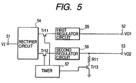
- Fig. 5 is a diagram which shows one structural example of the circuit that generates a predetermined voltage represented in Fig. 4 .
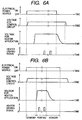
- Figs- 6A and 6B are timing charts which illustrate the rising waveform and the falling waveform of the output voltage of the predetermined voltage generating circuit shown in Fig. 4 .
- the ink jet head 4 of the present embodiment is structured to supply the voltage for heater application (10V to 40V) and the voltage for control circuit (3.3V or 5V) which is applied in order to drive the control circuit 45 from the predetermined voltage generating circuit 41, respectively.
- the predetermined voltage generating circuit 41 of the present embodiment comprises the rectifier circuit 54 that rectifies the input voltage VI received through the input terminal 51; a first regulator circuit 55 that outputs a desired voltage VO1 from the output terminal 52 by receiving the output voltage from the rectifier circuit 54 as input; a second regulator circuit 56 that outputs a desired voltage VO2 from the output terminal 53 by receiving the output voltage from the rectifier circuit 54 as input; a transistor Tr11 for turning on and off the input voltage to the first regulator circuit 55; a transistor Tr12 for turning on and off the input voltage to the second regulator circuit 56; and a timer 57 that controls the resistor R11 which discharges the output voltage from the second regulator circuit 56, and the transistor Tr13 as well, and also, controls turning on and off the transistors Tr11, Tr12, and Tr13 at specific timing, respectively.
- the first regulator circuit 55 and the second regulator circuit 56 are structured by the same circuit as the one shown in Fig. 2 , for example- Here, in Fig. 5 .
- the rectifier circuit 54 is arranged on assumption that a voltage of alternating current is supplied from the main body of a recording apparatus, but the rectifier circuit is not needed if a voltage of direct current is supplied from the main body of the recording apparatus.
- the circuit shown in Fig. 5 is arranged to turn on the transistor Tr11 earlier than the transistor Tr12 by use of the timer 57 when turning on the transistor Tr11 and transistor Tr12. Also, when turning off the transistor Tr11 and transistor Tr12, the transistor Tr12 is turned off and the transistor Tr13 is turned on. Then, the transistor Tr11 is turned off after the time has elapsed so that the output voltage from the second regulator circuit 56 is discharged sufficiently and becomes OV.
- the voltage VO1 output from the output terminal 52 is the voltage for control circuit
- the voltage VO2 output from the output terminal 53 is the voltage for heater application
- the voltage for heater application is supplied after the voltage for control circuit has been supplied, and the voltage for control circuit is turned off after the voltage for heater application has been turned off as shown in Fig. 6A .
- the application timing is controlled so that the voltage for heater application is on and off, while the voltage for control circuit is turned on at all the time, it becomes possible to prevent the malfunction of the heat generating elements 43, thus preventing the heat generating elements 43 from being damaged by any possible malfunction thereof that may take place otherwise.
- the reliability of the ink jet head is enhanced by protecting the heat generating elements 43 with the voltage for heater application which is supplied to the heat generating elements 43 only when printing is performed.
- Fig. 7 is a block diagram which shows the structure of an ink jet head in accordance with a third embodiment of the present invention.
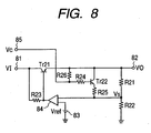
- Fig. 8 is a diagram which shows one structural example of the circuit that generates a predetermined voltage represented in Fig. 7 .
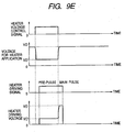
- Figs. 9A to 9E are timing charts which represent the voltage for heater use which is output from the predetermined voltage generating circuit shown in Fig. 7 , and also, the condition of heater driving voltage, which is applied to the heat generating elements.
- the ink jet head 7 of the present embodiment is structured to receive from outside the ink jet head 7 the signals VC for controlling the heater voltage for use of changing the output voltage VB of the predetermined voltage generating circuit 71.
- the output voltage VB of the predetermined voltage generating circuit 71 is supplied to the heater group 72 as the voltage for heater application, and the heat driving voltage, which is applied to each of the heat generating elements 73, is made variable from outside by the application of the signals VC for controlling heat voltage.
- the predetermined voltage generating circuit 71 of the present embodiment comprises the transistor Tr21 which is inserted between the input terminal 81 and the output terminal 82; the resistors R21 and R22 which detect the output voltage VO output from the output terminal 82 by dividing it; the resistor R23 which is inserted across the base collectors of the transistor Tr21; the reference voltage supply source 83 that outputs a predetermined reference voltage Vref; the differential amplifier circuit 84 that receives the detected voltage Vs detected by the resistors R21 and R22, and the reference voltage Vref as well, and controls the transistor TR21 to equalize the detected voltage Vs and reference voltage Vref; and the transistor Tr22 the base of which receives through the resistor R24 the signals VC for controlling the heater voltage inputted from the control terminal 85, and the collector of which is connected with the output terminal 82, and the emitter of which is connected with the input terminal in which the detected voltage Vs of the differential amplifier is inputted through the resistor R25.
- the heater driving voltage which is applicable to each of the heater generating elements (heaters) 73 as shown in Fig. 9A , can be changed in accordance with the resistive value of the heaters.
- the driving voltage can be adjusted per resistive value of heaters- Then, the pulse width is made smaller on the whole to make a higher speed possible.
- the heater driving voltage applicable to the heat generating elements 73 is made variable in accordance with the number of heaters to be driven at a time as shown in Fig. 9B .
- the heater driving voltage is changed to be equal to VO for the 9 to 16 locations of simultaneous driving from the heater driving voltage which is equal to VO' for the 1 to 8 locations thereof.
- the voltage drop between heaters can be compensated by use of the predetermined voltage generating circuit, hence making it possible to stabilize discharges irrespective of the number of heaters to be driven at the same time.
- the heater driving voltage applicable to the heat generating elements 73 in accordance with the frequency of heaters to be driven as shown in Fig. 9C .
- the heater driving voltage is equal to VO', but this setting is changed to be equal to VO if the discharge frequency is more than 20 kHz. In this way, the optimal driving is possible for each of the printing modes, respectively, so as to stabilize discharges accordingly.
- Fig. 9E shows the variational example of the one represented in Fig. 9D as the fifth embodiment.
- the signals VC for controlling the heater voltage is not necessarily limited to the one which is given from outside the ink jet head 7.
- the structure it may be possible to arrange the structure so that the signals are given from the control circuit 75.
- the predetermined voltage generating circuit should be arranged.
- the predetermined voltage generating circuit may be formed on a head base plate other than the elemental base plate where the heat generating elements are formed. Even in such a case, there is no particular problem in practice, and a desired voltage can be supplied to the heater group and the control circuit as well.
- the heaters (electrothermal transducing elements) 1106 which are arranged in plural numbers on the silicon base plate in order to create film boiling by generating the thermal energy which is utilized for discharging ink, and the electric wiring (not shown) of aluminum or the like which supplies electric power to the heaters are formed by the application of known film formation technologies and techniques.
- the heater board is positioned and fixed by the known bonding techniques.
- the wiring base plate 1108 is provided with the wiring which is connected with the wiring of the heater board 1107 by means of the known wiring bonding correspondently, and a plurality of pads 1109 which are positioned on the edge portion of the wiring to receive electric signals from the main body of the apparatus.
- the ceiling plate 1100 and the heater board 1107 are bonded while being positioned to be in agreement with the liquid flow paths 1103 and the heaters 1106, respectively, and fixed to the base plate 1110 together with the wiring base plate 1108, thus forming the ink jet recording head H.
- Fig. 11 is an exploded perspective view which schematically shows the ink jet head cartridge including the ink jet head described earlier. Roughly, the ink jet head cartridge is structured mainly with an ink discharge head unit 200 and an ink container 140.
- the ink discharge head unit 200 comprises an elemental base plate 151; a ceiling plate 153 with the discharge ports which are open to it; a pressure spring 128; an ink supply member 130; an aluminum base plate (supporting element) 120, among some others.
- a plurality of heat generating resistive elements are arranged in line to give heat to ink as described earlier.
- the liquid flow paths are formed by bonding the elemental base plate 151 and the ceiling plate 153 in order to distribute ink in them.
- the pressure spring 128 is a member that enables biasing force, which is directed to the elemental base plate 151, to act upon the ceiling plate 153.
- the ink container 140 contains ink to be supplied to the ink discharge head unit 200.
- a positioning member 144 for arranging the connecting member that connects the ink discharge head unit 200 and the ink container 140, and the fixing shaft 145 that fixes the connecting member.
- Ink is supplied to the ink supplies 131 and 132 of the ink supply member 130 through the ink supply paths 142 and 143 of the ink container 140, and then, supplied to the common liquid chamber through the liquid supply paths 133, 129, and 153c of each member.
- the ink supply from the ink container 140 to the ink supply member 130 is divided into two passages, but this supply is not necessarily divided.
- the ink container 140 may be used again by refilling ink therein.
- Fig. 12 is a view which schematically shows an ink jet recording apparatus on which the aforesaid ink jet head is installed.
- the carriage (scanning device) HC of the ink jet recording apparatus mounts on it the head cartridge provided with the ink container 140 that contains ink, and the ink discharge head unit 200 detachably.
- the carriage can reciprocate in the width direction (indicated by arrows a and b) of a recording medium 170, such as a recording sheet, which is carried by means for carrying a recording medium.
- the structure is arranged to make the ink container and the head unit separable from each other.
- Fig. 12 when driving signals are supplied from driving signal supply means (not shown) to ink discharge means on the carriage HC, recording ink is discharged from the ink head unit 200 to the recording medium 170 in accordance with such signals.
- the ink jet recording apparatus exemplified herein comprises a motor 161 which serves as the driving source to drive the recording medium carrying means and the carriage HC; the gears 162 and 163 which transmit the driving power from the driving source to the carriage HC; and a carriage shaft 164, among some others.
- the recording apparatus thus arranged, it is possible to obtain recorded objects of good images by discharging ink to each of the various kinds of recording media.
- Fig. 13 is a block diagram which shows the entire system to operate the ink jet recording apparatus to which the ink jet head of the present invention is applicable.
- the CPU 302 produces the driving data which are required to drive the driving motor 306 that enables the recording sheet and the head 200 to move in synchronism with the image data.
- the image data and the motor driving data are transmitted to the head 200 and the driving motor 306 through the head driver 307 and the motor driver 305.
- images are formed by them which are driven in accordance with the controlled timing, respectively.
- a recording medium applicable to the aforesaid recording apparatus which enables liquid, such as ink, to be provided therefor
- various kinds of objects paper, plastic materials used for OHP sheets, compact disks, or ornamental boards, cloths, metallic materials, such as aluminum, copper, leather materials, such cowhide, pigskin, artificial leathers, wood materials, such as woods, plywood, bamboo materials, ceramic materials, such as tiles, or three-dimensional structures, such as sponge, among some others.
- a printer that records on various kinds of paper, OHP sheets, or the like, a recording apparatus for use of plastics that records on compact discs or other plastic materials, a recording apparatus for use of metals that records on metallic plates, a recording apparatus for use of leathers that records on leathers, a recording apparatus for use of woods that records on woods, a recording apparatus for use of ceramics that records on ceramic materials, a recording apparatus for use of three-dimensional net structure, such as sponge, or a textile printing apparatus that records on textiles, or the like.
- ink may be used in accordance with each of the recording media and recording conditions.
- Fig. 14 is a view which schematically illustrates the structure of the ink jet recording apparatus that uses the ink jet head of the present invention described earlier.
- the ink jet head of the present embodiment is the head of full line type in which a plurality of discharge ports arranged at intervals of 360 dpi in a length corresponding to the recordable width of a recording medium. Then, four heads 201a to 201d, which correspond to yellow (Y), magenta (M), cyan (C), and black (Bk), respectively, are fixedly supported a holder 202 in parallel in the direction X at specific intervals.
- Y yellow
- M magenta
- C cyan
- Bk black
- each of the heads 201a to 201d signals are supplied from the head driver 307 which constitutes driving signal supply means, respectively. In accordance with such signals, each of the heads 201a to 201d is driven. Then, to each of the heads 201a to 201d, each of the four color ink Y, M, C, and Bk is supplied from each of the ink containers 204a to 204d.
- head caps 203a to 203d are arranged, each having sponge or some other ink absorbent in the interior thereof to cover the discharge ports of each head 201a to 201d for the maintenance of heads 201a to 201d.
- a reference numeral 206 designates a carrier belt that constitutes carrying means for carrying each kind of recording media described in conjunction with the previous example.
- the carrier belt 206 is drawn around various kinds of rollers through a specific passage, which is driven by driving rollers connected with the motor driver 305.
- a pre-processing device 251 and a post-processing device 252 which perform various processes of the recording medium before and after recording, are arranged on the upstream and downstream of the recording medium carrying path, respectively.
- the processing contents of the pre-process and post-process are different.
- a recording medium such as metal, plastic, ceramics
- a recording medium which easily generates static electricity such as plastics
- dust particles tend to adhere to the surface thereof easily. Then, due to the adhesion of such dust particles, good recording may be impeded in some cases.
- the pre-processing therefore, it is preferable to use an ionizer system to remove static electricity, thus removing dust particles from the recording medium.
- an ionizer system to remove static electricity, thus removing dust particles from the recording medium.
- cloths when cloths are used as a recording medium, it may be possible to execute a pre-processing by providing cloths with a substance that may be selected from among alkaline substances, water-soluble substances, synthetic polymer, water-soluble metallic salt, urea, and thiourea from the viewpoint of bleeding prevention, improvement of exhaustion degree, and the like.
- the pre-processing is not necessarily limited to those mentioned above. It may be possible to adopt a treatment or the like that makes the temperature of a recording medium to the one which is most suitable for the intended recording.
- the post-processing is such as to give heat treatment to a recording medium for which ink has been provided, fixing treatment that promotes the fixation of ink by the irradiation of ultraviolet rays or the like, a treatment that rinses off the processing agent which has been used for the pre-processing but still remains inactive, or the like.
- the present invention is not necessarily limited thereto. It may be possible to adopt a mode in which a small head is carried in the width direction of a recording medium for recording.
- the present invention is also applicable to the ink jet head that uses the piezoelectric elements as the recording elements that discharge ink by piezo-effect or the thermal head that uses heat generating elements.
Landscapes
- Particle Formation And Scattering Control In Inkjet Printers (AREA)
- Ink Jet (AREA)
Claims (15)
- Aufzeichnungskopf mit:einer Vielzahl von Aufzeichnungselementen (33; 43; 73) zum Aufzeichnen auf einem Aufzeichnungsmedium;einer Ansteuerschaltung zum Ansteuern der Vielzahl von Aufzeichnungselementen; undeiner Spannungszuführeinrichtung (31; 41; 71) für den Aufzeichnungskopf, mit einer Spannungserzeugungsschaltung (31; 41; 71) zum Erzeugen einer Vielzahl von unterschiedlichen Spannungen für den Aufzeichnungskopf aus einer extern zugeführten Spannung,dadurch gekennzeichnet, dassdie Spannungserzeugungsschaltung (41) betreibbar ist, aus der extern zugeführten Spannung eine Aufzeichnungselementspannung (VB2) für die Aufzeichnungselemente und eine Steuerschaltungsspannung (VB1) für eine Steuerschaltung (45) zum Steuern der Ansteuerschaltung zu erzeugen; unddie Spannungserzeugungsschaltung betreibbar ist, zu veranlassen, dass die jeweiligen Spannungen an die Steuerschaltung (45) und die Aufzeichnungselemente (43) zu unterschiedlichen Zeitpunkten angelegt werden, so dass die Steuerschaltungsspannung vor der Aufzeichnungselementspannung angelegt wird.
- Aufzeichnungskopf mit:einer Vielzahl von Aufzeichnungselementen (33; 43; 73) zum Aufzeichnen auf einem Aufzeichnungsmedium;einer Ansteuerschaltung zum Ansteuern der Vielzahl von Aufzeichnungselementen; undeiner Spannungszuführeinrichtung (31; 41; 71) für den Aufzeichnungskopf, mit einer Spannungserzeugungsschaltung (31; 41; 71) zum Erzeugen einer Vielzahl von unterschiedlichen Spannungen für den Aufzeichnungskopf aus einer extern zugeführten Spannung,dadurch gekennzeichnet, dassdie Spannungserzeugungsschaltung (41) betreibbar ist, aus der extern zugeführten Spannung eine Aufzeichnungselementspannung (VB2) für die Aufzeichnungselemente und eine Steuerschaltungsspannung (VB1) für eine Steuerschaltung (45) zum Steuern der Ansteuerschaltung zu erzeugen; unddie Spannungserzeugungsschaltung (41) betreibbar ist, zu veranlassen, dass die Aufzeichnungselement- und die Steuerschaltungsspannungen (VB2 und VB1) zu unterschiedlichen Zeitpunkten ausgeschaltet werden, so dass die Aufzeichnungselementspannung vor der Steuerschaltungsspannung ausgeschaltet wird.
- Aufzeichnungskopf gemäß Anspruch 1 oder 2, wobei die Vielzahl von Aufzeichnungselementen (33) in mehrere Gruppen (321, 322) von Aufzeichnungselementen aufgeteilt ist und die Spannungserzeugungsschaltung (31) betreibbar ist, jeweilige Spannungen für jede individuelle Gruppe aus der extern zugeführten Spannung zu erzeugen.
- Aufzeichnungskopf gemäß einem vorangegangenen Anspruch, wobei die Spannungserzeugungsschaltung (41) betreibbar ist, eine Spannung an die Aufzeichnungselemente nur zum Aufzeichnen anzulegen.
- Aufzeichnungskopf gemäß Anspruch 1 oder 2, wobei die Spannungserzeugungsschaltung (71) betreibbar ist, den Wert einer erzeugten Spannung gemäß spezifischen Steuersignalen zu ändern.
- Aufzeichnungskopf gemäß Anspruch 1 oder 2, wobei die Aufzeichnungselemente Widerstandswerte aufweisen und die Spannungserzeugungsschaltung betreibbar ist, verschiedene Spannungen für die Aufzeichnungselemente gemäß den Widerstandswerten der Aufzeichnungselemente bereitzustellen.
- Aufzeichnungskopf gemäß Anspruch 1 oder 2, wobei die Spannungserzeugungsschaltung betreibbar ist, eine Vielzahl von unterschiedlichen Spannungen gemäß der Anzahl von Aufzeichnungselementen bereitzustellen, die simultan anzusteuern sind.
- Aufzeichnungskopf gemäß Anspruch 1 oder 2, wobei die Spannungserzeugungsschaltung betreibbar ist, eine Vielzahl von unterschiedlichen Spannungen gemäß der Ansteuerfrequenz der Aufzeichnungselemente bereitzustellen.
- Aufzeichnungskopf gemäß Anspruch 1 oder 2, wobei die Ansteuerschaltung betreibbar ist, die Aufzeichnungselemente unter Verwendung eines Vorheizimpulses und eines Hauptimpulses anzusteuern, und die Spannungserzeugungsschaltung betreibbar ist, unterschiedliche Spannungen für die Vorheiz- und Hauptimpulse zu erzeugen.
- Aufzeichnungskopf gemäß Anspruch 9, wobei die Spannungserzeugungsschaltung betreibbar ist, die Spannungen für die Vorheiz- und Hauptimpulse zu erzeugen, so dass die Hauptimpulsspannung größer als die Vorheizimpulsspannung ist.
- Aufzeichnungskopf gemäß Anspruch 1 oder 3, wobei die Spannungserzeugungsschaltung (31) eine jeweilige Spannungserzeugungsschaltung zum Erzeugen jeder Spannung umfasst, wobei jede Spannungserzeugungsschaltung einen Spannungsteiler (R1, R2) zum Bereitstellen einer geteilten Spannung (Vs), die einen Anteil der extern zugeführten Spannung darstellt, eine Referenzspannungsquelle (23) zum Bereitstellen einer Referenzspannung (Vref), und einen Differentialverstärker (24) zum Empfangen der geteilten Spannung (Vs) und der Referenzspannung (Vref) von der Referenzspannungsquelle bei jeweiligen Eingängen umfasst, wobei der Ausgang des Differentialverstärkers (24) mit der Basiselektrode eines Transistors (Tr1) gekoppelt ist, bei dem eine von seinen Emitter- und Kollektorelektroden mit dem Eingang (V1) gekoppelt ist und die andere mit dem Ausgang (V0) der Spannungserzeugungsschaltung gekoppelt ist, wodurch, während eines Betriebs der Spannungserzeugungsschaltung, der Basisstrom des Transistors (Tr1) durch den Differentialverstärker (24) derartig gesteuert wird, um die geteilte Spannung (Vs) und die Referenzspannung (Vref) abzugleichen.
- Aufzeichnungskopf gemäß Anspruch 11, wobei jeweilige Schalter (TR11 und TR12) zum Steuern der Zuführung der extern zugeführten Spannung an die Spannungserzeugungsschaltungen (55 und 56) bereitgestellt sind.
- Aufzeichnungskopf gemäß Anspruch 1 oder 3, wobei die Spannungserzeugungsschaltung (71) eine jeweilige Spannungserzeugungsschaltung zum Erzeugen jeder Spannung umfasst, wobei jede Spannungserzeugungsschaltung einen Spannungsteiler (R21, R22) zum Bereitstellen einer geteilten Spannung (Vs), die einen Anteil der extern zugeführten Spannung darstellt, eine Referenzspannungsquelle (83) zum Bereitstellen einer Referenzspannung (Vref), und einen Differentialverstärker (84) zum Empfangen der geteilten Spannung (Vs) und der Referenzspannung (Vref) von der Referenzspannungsquelle bei jeweiligen Eingängen umfasst, wobei der Ausgang des Differentialverstärkers (84) mit der Basiselektrode eines Transistors (Tr21) gekoppelt ist, bei dem eine von seinen Emitter- und Kollektorelektroden mit dem Eingang (V1) gekoppelt ist und die andere mit dem Ausgang (V0) der Spannungserzeugungsschaltung gekoppelt ist, wodurch, während eines Betriebs der Spannungserzeugungsschaltung, der Basisstrom des Transistors (Tr21) durch den Differentialverstärker (84) derartig gesteuert wird, um die geteilte Spannung (Vs) und die Referenzspannung (Vref) abzugleichen;
weiterhin mit einem zusätzlichen Transistor (Tr22), der eine Basiselektrode aufweist, die gekoppelt ist, um ein Steuersignal (Vc) zu empfangen, wobei der Transistor mit einem Widerstand (R25) in Reihe gekoppelt ist, wobei die Transistor- (Tr22) und Widerstands- (R25) Kombination über einen der Widerstände (R21) des Spannungsteilers gekoppelt ist, um zu ermöglichen, dass die geteilte Spannung gemäß dem Steuersignal (Vc) geändert wird. - Aufzeichnungskopf gemäß einem vorangegangenen Anspruch, der eine Grundplatte aufweist, auf der die Spannungserzeugungsschaltung und Aufzeichnungselemente bereitgestellt werden.
- Aufzeichnungsvorrichtung mit:einem Aufzeichnungskopf gemäß einem der Ansprüche 1 bis 14;einem Schlitten zum Tragen des Aufzeichnungskopfs; undeiner Spannungserzeugungseinrichtung zum Erzeugen der extern zugeführten Spannung.
Applications Claiming Priority (2)
| Application Number | Priority Date | Filing Date | Title |
|---|---|---|---|
| JP16737599 | 1999-06-14 | ||
| JP16737599 | 1999-06-14 |
Publications (3)
| Publication Number | Publication Date |
|---|---|
| EP1060891A2 EP1060891A2 (de) | 2000-12-20 |
| EP1060891A3 EP1060891A3 (de) | 2001-03-21 |
| EP1060891B1 true EP1060891B1 (de) | 2008-07-23 |
Family
ID=15848559
Family Applications (1)
| Application Number | Title | Priority Date | Filing Date |
|---|---|---|---|
| EP00304914A Expired - Lifetime EP1060891B1 (de) | 1999-06-14 | 2000-06-09 | Aufzeichnungskopf und Aufzeichnungsgerät |
Country Status (9)
| Country | Link |
|---|---|
| US (3) | US6439680B1 (de) |
| EP (1) | EP1060891B1 (de) |
| KR (1) | KR100375288B1 (de) |
| CN (1) | CN1309570C (de) |
| AU (1) | AU776826B2 (de) |
| CA (1) | CA2311017C (de) |
| DE (1) | DE60039553D1 (de) |
| SG (1) | SG115340A1 (de) |
| TW (1) | TW510853B (de) |
Families Citing this family (29)
| Publication number | Priority date | Publication date | Assignee | Title |
|---|---|---|---|---|
| AUPP702498A0 (en) * | 1998-11-09 | 1998-12-03 | Silverbrook Research Pty Ltd | Image creation method and apparatus (ART77) |
| US6439680B1 (en) * | 1999-06-14 | 2002-08-27 | Canon Kabushiki Kaisha | Recording head, substrate for use of recording head, and recording apparatus |
| JP2002095272A (ja) * | 2000-09-11 | 2002-03-29 | Minolta Co Ltd | 駆動装置 |
| JP2003145765A (ja) * | 2001-11-15 | 2003-05-21 | Canon Inc | 記録装置およびその吐出方法 |
| US6789871B2 (en) | 2002-12-27 | 2004-09-14 | Lexmark International, Inc. | Reduced size inkjet printhead heater chip having integral voltage regulator and regulating capacitors |
| ES2345985T3 (es) | 2003-08-25 | 2010-10-07 | Dip Tech. Ltd. | Tinta para superficies ceramicas. |
| US7344218B2 (en) * | 2003-11-06 | 2008-03-18 | Canon Kabushiki Kaisha | Printhead driving method, printhead substrate, printhead, head cartridge and printing apparatus |
| TWI267446B (en) * | 2003-11-06 | 2006-12-01 | Canon Kk | Printhead substrate, printhead using the substrate, head cartridge including the printhead, method of driving the printhead, and printing apparatus using the printhead |
| CN100496980C (zh) * | 2004-06-02 | 2009-06-10 | 佳能株式会社 | 头基板、记录头、头盒及记录装置 |
| TWI239897B (en) * | 2004-08-05 | 2005-09-21 | Benq Corp | Method for optimizing ink jet from nozzles of a print-head of a printer |
| JP4614388B2 (ja) * | 2005-04-01 | 2011-01-19 | キヤノン株式会社 | 記録装置、記録ヘッド及びその駆動方法 |
| JP4845412B2 (ja) * | 2005-04-04 | 2011-12-28 | キヤノン株式会社 | 記録ヘッド、記録ヘッドカートリッジ、記録装置 |
| US7472975B2 (en) * | 2005-07-08 | 2009-01-06 | Canon Kabushiki Kaisha | Substrate for ink jet printing head, ink jet printing head, ink jet printing apparatus, and method of blowing fuse element of ink jet printing head |
| AU2006349360A1 (en) * | 2006-10-09 | 2008-04-17 | Silverbrook Research Pty Ltd | MEMS bubble generator for large stable vapor bubbles |
| US7491911B2 (en) | 2006-10-10 | 2009-02-17 | Silverbrook Research Pty Ltd | MEMS bubble generator for large stable vapor bubbles |
| JP4926691B2 (ja) * | 2006-12-21 | 2012-05-09 | キヤノン株式会社 | インクジェット記録ヘッド、およびインクジェット記録ヘッドの製造方法 |
| US7661782B2 (en) * | 2007-04-19 | 2010-02-16 | Lexmark International, Inc. | Current control circuit for micro-fluid ejection device heaters |
| US8235485B2 (en) * | 2007-05-01 | 2012-08-07 | Canon Kabushiki Kaisha | Element substrate, printhead, head cartridge, and printing apparatus |
| JP4905414B2 (ja) * | 2008-06-04 | 2012-03-28 | セイコーエプソン株式会社 | 液状体吐出装置、液状体の吐出方法および電気光学装置の製造方法 |
| JP5393596B2 (ja) | 2010-05-31 | 2014-01-22 | キヤノン株式会社 | インクジェット記録装置 |
| JP5708056B2 (ja) * | 2011-03-08 | 2015-04-30 | 株式会社リコー | 電源装置および電源装置の制御方法、ならびに、画像形成装置 |
| JP6504905B2 (ja) | 2015-05-08 | 2019-04-24 | キヤノン株式会社 | 液体吐出ヘッド及び該ヘッドのクリーニング方法、並びに記録装置 |
| JP6686425B2 (ja) * | 2015-12-25 | 2020-04-22 | セイコーエプソン株式会社 | ヘッドユニット制御回路 |
| JP6895717B2 (ja) | 2016-06-01 | 2021-06-30 | キヤノン株式会社 | 素子基板および記録装置 |
| JP7107167B2 (ja) * | 2018-10-30 | 2022-07-27 | セイコーエプソン株式会社 | 液体吐出装置及び駆動回路 |
| JP7151379B2 (ja) * | 2018-10-30 | 2022-10-12 | セイコーエプソン株式会社 | 液体吐出装置及び駆動回路 |
| WO2020255188A1 (ja) * | 2019-06-17 | 2020-12-24 | コニカミノルタ株式会社 | 記録ヘッドの駆動回路及び画像記録装置 |
| US11807006B2 (en) * | 2020-12-29 | 2023-11-07 | Memjet Technology Limited | Inkjet printhead assembly with wirebond protection |
| CN113879007B (zh) * | 2021-09-01 | 2022-11-25 | 北京蓝印科技有限公司 | 喷头加热自保护电路、喷头、打印机及加热方法 |
Family Cites Families (24)
| Publication number | Priority date | Publication date | Assignee | Title |
|---|---|---|---|---|
| CA1127227A (en) | 1977-10-03 | 1982-07-06 | Ichiro Endo | Liquid jet recording process and apparatus therefor |
| JPS6013571A (ja) * | 1983-07-04 | 1985-01-24 | Sony Corp | 印画装置 |
| JPS6075068U (ja) | 1983-10-28 | 1985-05-25 | アルプス電気株式会社 | 印字装置 |
| US4573058A (en) | 1985-05-24 | 1986-02-25 | Ncr Canada Ltd - Ncr Canada Ltee | Closed loop thermal printer for maintaining constant printing energy |
| JPH0673344B2 (ja) * | 1987-04-08 | 1994-09-14 | 株式会社日立製作所 | 電子線描画方法 |
| US4982199A (en) * | 1988-12-16 | 1991-01-01 | Hewlett-Packard Company | Method and apparatus for gray scale printing with a thermal ink jet pen |
| US5172134A (en) * | 1989-03-31 | 1992-12-15 | Canon Kabushiki Kaisha | Ink jet recording head, driving method for same and ink jet recording apparatus |
| US5083137A (en) | 1991-02-08 | 1992-01-21 | Hewlett-Packard Company | Energy control circuit for a thermal ink-jet printhead |
| CA2074906C (en) * | 1991-08-01 | 2000-09-12 | Hiromitsu Hirabayashi | Ink jet recording apparatus having temperature control function |
| US6076919A (en) * | 1991-08-12 | 2000-06-20 | Canon Kabushiki Kaisha | Jet recording method |
| EP0554820B1 (de) | 1992-02-03 | 1998-07-08 | Lanxide Technology Company, Lp | Verfahren zur Herstellung von keramischen Blättern |
| JPH0624863A (ja) | 1992-07-13 | 1994-02-01 | Mitsubishi Materials Corp | 軽量セッターの製造方法 |
| US6243111B1 (en) * | 1993-09-02 | 2001-06-05 | Canon Kabushiki Kaisha | Print head substrate, print head using the same, and printing apparatus |
| JPH07251506A (ja) | 1994-02-18 | 1995-10-03 | Xerox Corp | 加熱素子制御システム |
| US6116714A (en) | 1994-03-04 | 2000-09-12 | Canon Kabushiki Kaisha | Printing head, printing method and apparatus using same, and apparatus and method for correcting said printing head |
| US5995127A (en) * | 1994-09-13 | 1999-11-30 | Kabushiki Kaisha Toshiba | Thermal print head and manufacturing method thereof |
| US5751302A (en) * | 1996-03-29 | 1998-05-12 | Xerox Corporation | Transducer power dissipation control in a thermal ink jet printhead |
| JPH1024584A (ja) | 1996-07-12 | 1998-01-27 | Canon Inc | 液体吐出ヘッドカートリッジおよび液体吐出装置 |
| EP1332876B1 (de) | 1996-09-09 | 2006-03-22 | Seiko Epson Corporation | Tintenstrahldrucker und Druckverfahren |
| US6168251B1 (en) * | 1996-12-18 | 2001-01-02 | Canon Kabushiki Kaisha | Recording apparatus and method for correcting offset of recorded pixels |
| JP3311284B2 (ja) * | 1997-10-24 | 2002-08-05 | キヤノン株式会社 | 液体吐出記録ヘッド、液体吐出記録方法および液体吐出記録装置 |
| US6334660B1 (en) * | 1998-10-31 | 2002-01-01 | Hewlett-Packard Company | Varying the operating energy applied to an inkjet print cartridge based upon the operating conditions |
| US6186610B1 (en) * | 1998-09-21 | 2001-02-13 | Eastman Kodak Company | Imaging apparatus capable of suppressing inadvertent ejection of a satellite ink droplet therefrom and method of assembling same |
| US6439680B1 (en) * | 1999-06-14 | 2002-08-27 | Canon Kabushiki Kaisha | Recording head, substrate for use of recording head, and recording apparatus |
-
2000
- 2000-06-08 US US09/589,159 patent/US6439680B1/en not_active Expired - Lifetime
- 2000-06-08 CA CA002311017A patent/CA2311017C/en not_active Expired - Fee Related
- 2000-06-09 TW TW089111334A patent/TW510853B/zh not_active IP Right Cessation
- 2000-06-09 DE DE60039553T patent/DE60039553D1/de not_active Expired - Lifetime
- 2000-06-09 SG SG200003217A patent/SG115340A1/en unknown
- 2000-06-09 EP EP00304914A patent/EP1060891B1/de not_active Expired - Lifetime
- 2000-06-13 AU AU39442/00A patent/AU776826B2/en not_active Ceased
- 2000-06-14 KR KR10-2000-0032647A patent/KR100375288B1/ko not_active Expired - Fee Related
- 2000-06-14 CN CNB001183907A patent/CN1309570C/zh not_active Expired - Fee Related
-
2002
- 2002-07-05 US US10/189,230 patent/US7108345B2/en not_active Expired - Fee Related
-
2004
- 2004-10-29 US US10/975,533 patent/US7055923B2/en not_active Expired - Fee Related
Also Published As
| Publication number | Publication date |
|---|---|
| TW510853B (en) | 2002-11-21 |
| US6439680B1 (en) | 2002-08-27 |
| KR20010007368A (ko) | 2001-01-26 |
| CN1309570C (zh) | 2007-04-11 |
| DE60039553D1 (de) | 2008-09-04 |
| KR100375288B1 (ko) | 2003-03-10 |
| EP1060891A2 (de) | 2000-12-20 |
| AU776826B2 (en) | 2004-09-23 |
| CN1277111A (zh) | 2000-12-20 |
| EP1060891A3 (de) | 2001-03-21 |
| AU3944200A (en) | 2000-12-21 |
| US20050057589A1 (en) | 2005-03-17 |
| US7055923B2 (en) | 2006-06-06 |
| US20020171696A1 (en) | 2002-11-21 |
| SG115340A1 (en) | 2005-10-28 |
| CA2311017C (en) | 2004-07-20 |
| US7108345B2 (en) | 2006-09-19 |
| CA2311017A1 (en) | 2000-12-14 |
Similar Documents
| Publication | Publication Date | Title |
|---|---|---|
| EP1060891B1 (de) | Aufzeichnungskopf und Aufzeichnungsgerät | |
| EP0390202B1 (de) | Tintenstrahlaufzeichnungskopf, Betriebsart und Tintenstrahlaufzeichnungsgerät | |
| US7802858B2 (en) | Element board for printhead, printhead and printhead control method | |
| EP1057640B1 (de) | Tintenstrahlaufzeichnungskopf und Tintenstrahlaufzeichnungsgerät | |
| US6409315B2 (en) | Substrate for use of an ink jet recording head, an ink jet head using such substrate, a method for driving such substrate, and an jet head cartridge, and a liquid discharge apparatus | |
| US5281980A (en) | Ink jet recording head | |
| JP5032964B2 (ja) | ヘッド基板、記録ヘッド、ヘッドカートリッジ、及び記録装置 | |
| JP4856806B2 (ja) | 記録ヘッド、記録ヘッド用基体および記録装置 | |
| US7441853B2 (en) | Image forming apparatus and drive control method for liquid ejection head | |
| US5638100A (en) | Ink jet and ink preliminary ejecting method | |
| KR20020083477A (ko) | 프린트 장치 및 프린트 제어 방법 | |
| US20160221334A1 (en) | Address architecture for fluid ejection chip | |
| JP2001047630A (ja) | インクジェット記録ヘッド、及びインクジェット記録装置 | |
| JP3563883B2 (ja) | インクジェットヘッド及びインクジェットヘッド用基板 | |
| JP2009056649A (ja) | 記録装置、及びその記録制御方法 | |
| JP2008094012A (ja) | インクジェット記録装置およびインクジェット記録装置の制御方法 | |
| JPH03234629A (ja) | 画像記録装置 | |
| JP2781242B2 (ja) | 記録ヘッド駆動装置および前記駆動装置を用いた記録装置 | |
| JP2009143017A (ja) | 素子基板、及びその素子基板を有する記録ヘッド、ヘッドカートリッジ、記録装置 | |
| JP2005169866A (ja) | 記録ヘッド及びその記録ヘッドを用いた記録装置 | |
| JPH04133752A (ja) | 記録装置 |
Legal Events
| Date | Code | Title | Description |
|---|---|---|---|
| PUAI | Public reference made under article 153(3) epc to a published international application that has entered the european phase |
Free format text: ORIGINAL CODE: 0009012 |
|
| AK | Designated contracting states |
Kind code of ref document: A2 Designated state(s): AT BE CH CY DE DK ES FI FR GB GR IE IT LI LU MC NL PT SE |
|
| AX | Request for extension of the european patent |
Free format text: AL;LT;LV;MK;RO;SI |
|
| PUAL | Search report despatched |
Free format text: ORIGINAL CODE: 0009013 |
|
| AK | Designated contracting states |
Kind code of ref document: A3 Designated state(s): AT BE CH CY DE DK ES FI FR GB GR IE IT LI LU MC NL PT SE |
|
| AX | Request for extension of the european patent |
Free format text: AL;LT;LV;MK;RO;SI |
|
| 17P | Request for examination filed |
Effective date: 20010806 |
|
| AKX | Designation fees paid |
Free format text: DE ES FR GB IT NL |
|
| 17Q | First examination report despatched |
Effective date: 20050209 |
|
| RTI1 | Title (correction) |
Free format text: RECORDING HEAD AND RECORDING APPARATUS |
|
| GRAP | Despatch of communication of intention to grant a patent |
Free format text: ORIGINAL CODE: EPIDOSNIGR1 |
|
| GRAS | Grant fee paid |
Free format text: ORIGINAL CODE: EPIDOSNIGR3 |
|
| GRAA | (expected) grant |
Free format text: ORIGINAL CODE: 0009210 |
|
| AK | Designated contracting states |
Kind code of ref document: B1 Designated state(s): DE ES FR GB IT NL |
|
| REG | Reference to a national code |
Ref country code: GB Ref legal event code: FG4D |
|
| REF | Corresponds to: |
Ref document number: 60039553 Country of ref document: DE Date of ref document: 20080904 Kind code of ref document: P |
|
| NLV1 | Nl: lapsed or annulled due to failure to fulfill the requirements of art. 29p and 29m of the patents act | ||
| PG25 | Lapsed in a contracting state [announced via postgrant information from national office to epo] |
Ref country code: ES Free format text: LAPSE BECAUSE OF FAILURE TO SUBMIT A TRANSLATION OF THE DESCRIPTION OR TO PAY THE FEE WITHIN THE PRESCRIBED TIME-LIMIT Effective date: 20081103 Ref country code: NL Free format text: LAPSE BECAUSE OF FAILURE TO SUBMIT A TRANSLATION OF THE DESCRIPTION OR TO PAY THE FEE WITHIN THE PRESCRIBED TIME-LIMIT Effective date: 20080723 |
|
| PLBE | No opposition filed within time limit |
Free format text: ORIGINAL CODE: 0009261 |
|
| STAA | Information on the status of an ep patent application or granted ep patent |
Free format text: STATUS: NO OPPOSITION FILED WITHIN TIME LIMIT |
|
| 26N | No opposition filed |
Effective date: 20090424 |
|
| PG25 | Lapsed in a contracting state [announced via postgrant information from national office to epo] |
Ref country code: IT Free format text: LAPSE BECAUSE OF FAILURE TO SUBMIT A TRANSLATION OF THE DESCRIPTION OR TO PAY THE FEE WITHIN THE PRESCRIBED TIME-LIMIT Effective date: 20080723 |
|
| REG | Reference to a national code |
Ref country code: FR Ref legal event code: PLFP Year of fee payment: 17 |
|
| REG | Reference to a national code |
Ref country code: FR Ref legal event code: PLFP Year of fee payment: 18 |
|
| PGFP | Annual fee paid to national office [announced via postgrant information from national office to epo] |
Ref country code: FR Payment date: 20170626 Year of fee payment: 18 Ref country code: GB Payment date: 20170614 Year of fee payment: 18 |
|
| PGFP | Annual fee paid to national office [announced via postgrant information from national office to epo] |
Ref country code: DE Payment date: 20170630 Year of fee payment: 18 |
|
| REG | Reference to a national code |
Ref country code: DE Ref legal event code: R119 Ref document number: 60039553 Country of ref document: DE |
|
| GBPC | Gb: european patent ceased through non-payment of renewal fee |
Effective date: 20180609 |
|
| PG25 | Lapsed in a contracting state [announced via postgrant information from national office to epo] |
Ref country code: GB Free format text: LAPSE BECAUSE OF NON-PAYMENT OF DUE FEES Effective date: 20180609 Ref country code: FR Free format text: LAPSE BECAUSE OF NON-PAYMENT OF DUE FEES Effective date: 20180630 Ref country code: DE Free format text: LAPSE BECAUSE OF NON-PAYMENT OF DUE FEES Effective date: 20190101 |