EP1060919A2 - Carrosserie de camion - Google Patents
Carrosserie de camion Download PDFInfo
- Publication number
- EP1060919A2 EP1060919A2 EP00660111A EP00660111A EP1060919A2 EP 1060919 A2 EP1060919 A2 EP 1060919A2 EP 00660111 A EP00660111 A EP 00660111A EP 00660111 A EP00660111 A EP 00660111A EP 1060919 A2 EP1060919 A2 EP 1060919A2
- Authority
- EP
- European Patent Office
- Prior art keywords
- roof
- edge
- side wall
- hydraulic cylinder
- trailer body
- Prior art date
- Legal status (The legal status is an assumption and is not a legal conclusion. Google has not performed a legal analysis and makes no representation as to the accuracy of the status listed.)
- Withdrawn
Links
- 230000007246 mechanism Effects 0.000 claims abstract description 13
- 229910000831 Steel Inorganic materials 0.000 description 1
- 238000010276 construction Methods 0.000 description 1
- 238000005265 energy consumption Methods 0.000 description 1
- 238000009413 insulation Methods 0.000 description 1
- 238000005057 refrigeration Methods 0.000 description 1
- 239000010959 steel Substances 0.000 description 1
Images


Classifications
-
- B—PERFORMING OPERATIONS; TRANSPORTING
- B60—VEHICLES IN GENERAL
- B60J—WINDOWS, WINDSCREENS, NON-FIXED ROOFS, DOORS, OR SIMILAR DEVICES FOR VEHICLES; REMOVABLE EXTERNAL PROTECTIVE COVERINGS SPECIALLY ADAPTED FOR VEHICLES
- B60J7/00—Non-fixed roofs; Roofs with movable panels, e.g. rotary sunroofs
- B60J7/08—Non-fixed roofs; Roofs with movable panels, e.g. rotary sunroofs of non-sliding type, i.e. movable or removable roofs or panels, e.g. let-down tops or roofs capable of being easily detached or of assuming a collapsed or inoperative position
- B60J7/12—Non-fixed roofs; Roofs with movable panels, e.g. rotary sunroofs of non-sliding type, i.e. movable or removable roofs or panels, e.g. let-down tops or roofs capable of being easily detached or of assuming a collapsed or inoperative position foldable; Tensioning mechanisms therefor, e.g. struts
- B60J7/14—Non-fixed roofs; Roofs with movable panels, e.g. rotary sunroofs of non-sliding type, i.e. movable or removable roofs or panels, e.g. let-down tops or roofs capable of being easily detached or of assuming a collapsed or inoperative position foldable; Tensioning mechanisms therefor, e.g. struts with a plurality of rigid plate-like elements or rigid non plate-like elements, e.g. with non-slidable, but pivotable or foldable movement
- B60J7/141—Non-fixed roofs; Roofs with movable panels, e.g. rotary sunroofs of non-sliding type, i.e. movable or removable roofs or panels, e.g. let-down tops or roofs capable of being easily detached or of assuming a collapsed or inoperative position foldable; Tensioning mechanisms therefor, e.g. struts with a plurality of rigid plate-like elements or rigid non plate-like elements, e.g. with non-slidable, but pivotable or foldable movement for covering load areas, e.g. for pick-up trucks
-
- B—PERFORMING OPERATIONS; TRANSPORTING
- B60—VEHICLES IN GENERAL
- B60J—WINDOWS, WINDSCREENS, NON-FIXED ROOFS, DOORS, OR SIMILAR DEVICES FOR VEHICLES; REMOVABLE EXTERNAL PROTECTIVE COVERINGS SPECIALLY ADAPTED FOR VEHICLES
- B60J5/00—Doors
- B60J5/04—Doors arranged at the vehicle sides
- B60J5/0497—Doors arranged at the vehicle sides for load transporting vehicles or public transport, e.g. lorries, trucks, buses
- B60J5/0498—Doors arranged at the vehicle sides for load transporting vehicles or public transport, e.g. lorries, trucks, buses with rigid panels pivoting about a horizontal axis
-
- B—PERFORMING OPERATIONS; TRANSPORTING
- B60—VEHICLES IN GENERAL
- B60J—WINDOWS, WINDSCREENS, NON-FIXED ROOFS, DOORS, OR SIMILAR DEVICES FOR VEHICLES; REMOVABLE EXTERNAL PROTECTIVE COVERINGS SPECIALLY ADAPTED FOR VEHICLES
- B60J5/00—Doors
- B60J5/04—Doors arranged at the vehicle sides
- B60J5/06—Doors arranged at the vehicle sides slidable; foldable
-
- B—PERFORMING OPERATIONS; TRANSPORTING
- B60—VEHICLES IN GENERAL
- B60J—WINDOWS, WINDSCREENS, NON-FIXED ROOFS, DOORS, OR SIMILAR DEVICES FOR VEHICLES; REMOVABLE EXTERNAL PROTECTIVE COVERINGS SPECIALLY ADAPTED FOR VEHICLES
- B60J7/00—Non-fixed roofs; Roofs with movable panels, e.g. rotary sunroofs
- B60J7/02—Non-fixed roofs; Roofs with movable panels, e.g. rotary sunroofs of sliding type, e.g. comprising guide shoes
- B60J7/04—Non-fixed roofs; Roofs with movable panels, e.g. rotary sunroofs of sliding type, e.g. comprising guide shoes with rigid plate-like element or elements, e.g. open roofs with harmonica-type folding rigid panels
- B60J7/041—Non-fixed roofs; Roofs with movable panels, e.g. rotary sunroofs of sliding type, e.g. comprising guide shoes with rigid plate-like element or elements, e.g. open roofs with harmonica-type folding rigid panels for utility vehicles, e.g. with slidable and foldable rigid panels
Definitions
- the invention is related to a truck trailer body and, more accurately, to a closed-top trailer body which includes a floor, a front wall, a back wall, two opposite sidewalls and a roof.
- the back wall includes doors through which loading and unloading are made.
- sidewalls include doors, often slide doors. Solutions are known also in which essentially the whole side wall of the body may be opened, e.g. by means of an arrangement of folding or sliding doors.
- U.S. Patent No. 4668008 One solution of this kind is presented in U.S. Patent No. 4668008. With such a solution, cargo loading and anloading is made faster and more flexible.
- a completely opening side wall is used in refrigerator or freezer trailer bodies, for example, with which it is often necessary to be able to load and unload goods in various places fast and in an order which is as optional as possible.
- An object of the invention is to provide a solution which alleviates problems described above.
- a truck trailer body which includes a floor, a front wall, a back wall, two opposite side walls and a roof, is characterized in that, for opening the body, it includes as a combination the following features: the roof is at a first edge thereof attaced pivotably to the top edge of one side wall; the other side wall is at the top edge thereof attached pivotably to a second edge, opposite to the first edge, of the roof; and a hydraulic cylinder or similarly operating device is placed adjacent to the top edge of the front wall and the back wall, respectively, which cylinder or device is, on one hand, attached pivotably to said top edge at a distance from the first side wall and, on the other hand, by means of a folding arm and link mechanism to a correponding end edge of the roof at a closer distance from the first side wall; for setting the hydraulic cylinder or similarly operating device in the rest position thereof essentially parallel with the corresponding top edge and, on the other hand, for enlarging the roof
- the arm and link mechanism includes an arm which is attached with a first pivotable attachment to the end edge of the roof and with a second pivotable attachement to the hydraulic cylinder or similarly operating device, and a foldable stop arrangement between the arm and the end edge of the roof for turning the arm in the rest position thereof essentially parallel with the hydraulic cylinder and the end edge of the roof and by the action of the pushing force of the hydraulic cylinder to an angle in relation to the end edge of the roof limited by the stop arrangement, for enlarging the rotative moment directed to the roof in the initial stage of the opening.
- the rod part of the hydraulic cylinder is attached to the upper corner of the end wall and the cylinder part to the middle part of the end edge of the roof.
- the floor, walls and roof of a trailer body may be insulated for refrigerated transport.
- the solution of the invention makes the loading and unloading of the trailer body easier.
- it reduces the number and length of joints to be sealed and simplifies also otherwise the construction in comparison with the corresponding solutions with completely opening side wall.
- the trailer body may be realized also in such a way that there are no support structures of e.g. steel which extend through the wall structure and conduct heat through the wall. Accordingly, the invention improves the tightness of a refrigerator trailer body and reduces energy consumption of reftrigerated transport.
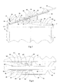
- Figs. 1 and 2 present, as a whole, a closed-top truck trailer body 1 which is used in a conventional way as attached to a frame 2 provided with wheels 3.
- the trailer body includes a floor 4, a front wall 5, a back wall 6 which is, as normally, provided with doors, a first side wall 7, a second side wall 8, and a roof 9.
- the roof 9 is attached pivotably to the top edge of the side wall 7, and the second side wall 8 is attached pivotably to the other edge of the roof.
- side wall 8 is raised with the roof and slides on the upper corners of the end walls 5 and 6.
- the side wall is folding towards the roof sliding now on the lower corners thereof which also are provided with rolls 23' and 23 for making the sliding easier.
- the whole area of the side wall and the most of the area of the roof are now open without any obstacles, so that with loading goods may be brought to the interior also from upper side directly and obliquely and that the goods may be unloaded, respectively, by lifting directly or obliquely upwards.
- Figs. 3 and 4 present, respectively, a simplified schematical cross section and longitudinal section of an embodiment of the trailer body according to the invention.
- the floor 4, the end walls 5 and 6 and the first side wall 7 form an integral structure which may be made, for example, of insulated wall elements joint to each other and reinforced with suitable support structures.
- the hinge arrangement 14 allows the roof 9 to turn from horizontal to vertical position and even further on.
- the hinge arrangement allows the wall 8 to turn towards the roof 9 from rectangular position in relation thereof.
- the hinge arrangements 14 and 15 may be formed of a hinge joint extending over the whole edge or of several separate hinges between the corresponding edges.
- the edge 16 of the floor 4 on the side of the opening side wall 8 is designed so that the lower edge 43 of the side wall may be supported and sealed properly against it.
- the edge 16 of the floor is provided with a gasket 27.
- the outside of the edge 16 of the floor is provided with means 17, 18 for supporting and latching the lower side 43 of the wall against the edge 16 of the floor.
- the supporting and latching means include arms 18 rotating on axle 17 hinged to the edge 16 of the floor and a latching mechanism (not shown).
- Fig. 4 illustrates schematically placing of the hydraulic cylinder units 30 and 30', formed by hydraulic cylinders and the attachment arrangements thereof, on the corresponding upper edges 29 and 28 of the end walls 6 and 5. Attachments to the upper edges 29 and 28 and the corresponding end edges 32 and 31 of the roof 9 are not presented here, an example of attachments being presented in further detail with reference to Figs. 5 and 6. Of course, there are also gaskets, which are not shown in Fig. 4, between the end edges of the roof and the corresponding upper edges of the end walls.
- refrigeration device is installed on the trailer body, normally in the vicinity of the front wall 5.
- Such accessories of the trailer body are not presented here.
- the rod part 20 of the hydraulic cylinder is attached pivotably to the upper corner 21 of the end wall 6, so that the cylinder is able to turn to the rest position thereof on the upper edge 29 of the end wall.
- a support structure including guide pieces 42 attached to the cylinder part 19 and a bar 43 sliding through the pieces and attached at the other end 44 thereof to the end of the rod part of the cylinder.
- the hydraulic cylinder For causing the hydraulic cylinder to raise the roof 9 in the initial stage of opening, it is attached to the end edge 32 of the roof with an arm and link mechanism 22 the plan view of which is shown in further detail in Fig. 6. For the sake of clarity, no hydraulic connections are shown in the figures.
- Support plate 33 is attached to the edge 32 of the roof with support bars 45 and 46 placed under the cylinder part 19.
- Short shafts 39, 39' are attached to the cylinder part 19 and, correspondingly, shafts 37, 37' attached to the support plate 33 and the edge 32 of the roof extending close to the cylinder part.
- corresponding arms 34, 34' are attached pivotably on which arms the cylinder 19, 20 turns obliquely upwards as the opening of the roof is started by means of the pushing force of the cylinder.
- arms 34, 34' and the support plate 33 and the edge 32 of the roof there is an arm mechanism formed by arms 35, 36; 35' 36' and shafts 38, 40, 41; 38', 40', 41', respectively, folding to the rest position and limiting the opening of arms 34, 34'.
- arm and link mechanism By means of the arm and link mechanism a big enough rotative moment is directed to the roof in the initial stage of the opening.
- a hydraulic cylinder instead of a hydraulic cylinder, a similarly operating technical device may be used which provides a long enough pushing between the upper edge of the end wall and the arm and link mechanism attached to the edge of the roof.
- a device may be a combination of a gear rack and gearwheel or a screw driven by an electric motor, for example.
- hydraulic cylinder is a preferred embodiment.
- a hydraulic cylinder (or a similarly operating device) may be attached at one end thereof closer to the first side wall at a suitable distance thereof and, correspondingly, the arm and link mechanism on the edge of the roof also closer to the first side wall, but the a bigger force is needed to lift the roof and the second side wall as the lever arm is shorter.
Landscapes
- Engineering & Computer Science (AREA)
- Mechanical Engineering (AREA)
- Body Structure For Vehicles (AREA)
- Vehicle Step Arrangements And Article Storage (AREA)
- Vehicle Cleaning, Maintenance, Repair, Refitting, And Outriggers (AREA)
- Handcart (AREA)
Applications Claiming Priority (2)
| Application Number | Priority Date | Filing Date | Title |
|---|---|---|---|
| FI991386 | 1999-06-17 | ||
| FI991386A FI106369B (fi) | 1999-06-17 | 1999-06-17 | Kuorma-auton kuljetuskori |
Publications (2)
| Publication Number | Publication Date |
|---|---|
| EP1060919A2 true EP1060919A2 (fr) | 2000-12-20 |
| EP1060919A3 EP1060919A3 (fr) | 2001-10-17 |
Family
ID=8554900
Family Applications (1)
| Application Number | Title | Priority Date | Filing Date |
|---|---|---|---|
| EP00660111A Withdrawn EP1060919A3 (fr) | 1999-06-17 | 2000-06-15 | Carrosserie de camion |
Country Status (3)
| Country | Link |
|---|---|
| EP (1) | EP1060919A3 (fr) |
| EE (1) | EE200000287A (fr) |
| FI (1) | FI106369B (fr) |
Cited By (2)
| Publication number | Priority date | Publication date | Assignee | Title |
|---|---|---|---|---|
| WO2001083328A1 (fr) * | 2000-05-03 | 2001-11-08 | Oy Langh Ship Ab | Conteneur de navire de charge |
| US20140271093A1 (en) * | 2013-03-14 | 2014-09-18 | Poet Research, Inc. | Self-strapping round bale trailer |
Citations (1)
| Publication number | Priority date | Publication date | Assignee | Title |
|---|---|---|---|---|
| US4668008A (en) | 1983-12-22 | 1987-05-26 | Kelsey-Hayes Company | Sliding door trailer |
Family Cites Families (3)
| Publication number | Priority date | Publication date | Assignee | Title |
|---|---|---|---|---|
| DE2919608A1 (de) * | 1979-05-16 | 1980-11-20 | Guenter Peters | Lastkraftwagen mit ladepritsche und aufbau |
| FR2518484B1 (fr) * | 1981-12-23 | 1986-08-29 | Guillarme Ind | Carrosserie pour vehicule servant au transport de marchandises |
| NL1004846C2 (nl) * | 1996-12-20 | 1998-06-23 | Gijsbertsen Bv | Overdekkingssamenstel voor een kipwagenhouder, kipwagenhouder omvattende een dergelijk samenstel, en een kipwagen waarop een zodanige houder is aangebracht. |
-
1999
- 1999-06-17 FI FI991386A patent/FI106369B/fi active
-
2000
- 2000-06-15 EP EP00660111A patent/EP1060919A3/fr not_active Withdrawn
- 2000-06-16 EE EEP200000287A patent/EE200000287A/xx unknown
Patent Citations (1)
| Publication number | Priority date | Publication date | Assignee | Title |
|---|---|---|---|---|
| US4668008A (en) | 1983-12-22 | 1987-05-26 | Kelsey-Hayes Company | Sliding door trailer |
Cited By (2)
| Publication number | Priority date | Publication date | Assignee | Title |
|---|---|---|---|---|
| WO2001083328A1 (fr) * | 2000-05-03 | 2001-11-08 | Oy Langh Ship Ab | Conteneur de navire de charge |
| US20140271093A1 (en) * | 2013-03-14 | 2014-09-18 | Poet Research, Inc. | Self-strapping round bale trailer |
Also Published As
| Publication number | Publication date |
|---|---|
| EP1060919A3 (fr) | 2001-10-17 |
| EE200000287A (et) | 2001-02-15 |
| FI991386A0 (fi) | 1999-06-17 |
| FI106369B (fi) | 2001-01-31 |
| FI991386A7 (fi) | 2000-12-18 |
Similar Documents
| Publication | Publication Date | Title |
|---|---|---|
| US6921492B2 (en) | Motor vehicle with a cargo space and cargo space door | |
| US4027912A (en) | Collapsible roof-top camper | |
| US7226108B2 (en) | Horizontal bed cover lift system | |
| US7631921B2 (en) | Closure system for a vehicle | |
| PL182228B1 (pl) | Scianka boczna nadwozia pojazdu PL | |
| NO823095L (no) | Stoetteanordning ved bil eller vogn med loeftbar sidelukke | |
| KR102313103B1 (ko) | 적재함의 높이 가변형 탑차 | |
| US6382731B1 (en) | Load hauling vehicle with sidewall raising and lowering mechanism | |
| EP1060919A2 (fr) | Carrosserie de camion | |
| US8500206B2 (en) | Mechanical tailgate | |
| JP4049573B2 (ja) | 壁面開閉装置付き車両荷台カバー構体 | |
| CN110395496A (zh) | 侧壁可开合的集装箱 | |
| EP1800945A2 (fr) | Porte de cargo pour véhicules, remorques et semi-remorques | |
| KR100427740B1 (ko) | 유개차형 화물차용 적재함 | |
| JP3066277U (ja) | ウイングル―フの開閉機構 | |
| JPH0960411A (ja) | コンテナ用跳ね上げ式扉の開閉装置 | |
| KR200185406Y1 (ko) | 화물차의 적재함 덮개 | |
| KR102511274B1 (ko) | 개폐구조가 개선된 냉동 윙바디 | |
| JP4709808B2 (ja) | 荷台後部側開口域拡張型ウイング車両 | |
| KR200252642Y1 (ko) | 유개차형 화물차용 적재함 | |
| JPH02171319A (ja) | 特装バン型車両の荷台構造 | |
| JPH0139613Y2 (fr) | ||
| KR950007126Y1 (ko) | 박스카의 도어개폐장치 | |
| KR200287432Y1 (ko) | 특장차 적재함의 날개형 구조체의 개폐구조 | |
| KR200153574Y1 (ko) | 화물자동차용 적재함의 개폐장치 |
Legal Events
| Date | Code | Title | Description |
|---|---|---|---|
| PUAI | Public reference made under article 153(3) epc to a published international application that has entered the european phase |
Free format text: ORIGINAL CODE: 0009012 |
|
| AK | Designated contracting states |
Kind code of ref document: A2 Designated state(s): AT BE CH CY DE DK ES FI FR GB GR IE IT LI LU MC NL PT SE |
|
| AX | Request for extension of the european patent |
Free format text: AL;LT;LV;MK;RO;SI |
|
| PUAL | Search report despatched |
Free format text: ORIGINAL CODE: 0009013 |
|
| AK | Designated contracting states |
Kind code of ref document: A3 Designated state(s): AT BE CH CY DE DK ES FI FR GB GR IE IT LI LU MC NL PT SE |
|
| AX | Request for extension of the european patent |
Free format text: AL;LT;LV;MK;RO;SI |
|
| RIC1 | Information provided on ipc code assigned before grant |
Free format text: 7B 60J 5/06 A, 7B 60J 7/14 B, 7B 60J 5/04 B |
|
| AKX | Designation fees paid |
Free format text: AT BE CH CY DE DK ES FI FR GB GR IE IT LI LU MC NL PT SE |
|
| STAA | Information on the status of an ep patent application or granted ep patent |
Free format text: STATUS: THE APPLICATION IS DEEMED TO BE WITHDRAWN |
|
| 18D | Application deemed to be withdrawn |
Effective date: 20020418 |