EP1060921A2 - Lamellendach für eine Dachöffnung eines Kraftfahrzeugs - Google Patents
Lamellendach für eine Dachöffnung eines Kraftfahrzeugs Download PDFInfo
- Publication number
- EP1060921A2 EP1060921A2 EP00112279A EP00112279A EP1060921A2 EP 1060921 A2 EP1060921 A2 EP 1060921A2 EP 00112279 A EP00112279 A EP 00112279A EP 00112279 A EP00112279 A EP 00112279A EP 1060921 A2 EP1060921 A2 EP 1060921A2
- Authority
- EP
- European Patent Office
- Prior art keywords
- slat
- carrier
- guide
- control rocker
- roof
- Prior art date
- Legal status (The legal status is an assumption and is not a legal conclusion. Google has not performed a legal analysis and makes no representation as to the accuracy of the status listed.)
- Granted
Links
- 230000007246 mechanism Effects 0.000 claims abstract description 16
- 241000446313 Lamella Species 0.000 claims description 44
- 238000006073 displacement reaction Methods 0.000 claims description 11
- 230000008878 coupling Effects 0.000 claims description 10
- 238000010168 coupling process Methods 0.000 claims description 10
- 238000005859 coupling reaction Methods 0.000 claims description 10
- 101100116424 Mus musculus Def6 gene Proteins 0.000 description 76
- 239000002131 composite material Substances 0.000 description 10
- 238000000034 method Methods 0.000 description 5
- 230000008569 process Effects 0.000 description 5
- 238000010276 construction Methods 0.000 description 4
- 230000007704 transition Effects 0.000 description 4
- 239000000969 carrier Substances 0.000 description 2
- 238000004519 manufacturing process Methods 0.000 description 2
- 230000005540 biological transmission Effects 0.000 description 1
- 230000001419 dependent effect Effects 0.000 description 1
- 238000005516 engineering process Methods 0.000 description 1
- 230000002349 favourable effect Effects 0.000 description 1
- 238000009434 installation Methods 0.000 description 1
- 230000003993 interaction Effects 0.000 description 1
- 238000003754 machining Methods 0.000 description 1
- 230000001404 mediated effect Effects 0.000 description 1
- 230000002028 premature Effects 0.000 description 1
- 230000003319 supportive effect Effects 0.000 description 1
Images



Classifications
-
- B—PERFORMING OPERATIONS; TRANSPORTING
- B60—VEHICLES IN GENERAL
- B60J—WINDOWS, WINDSCREENS, NON-FIXED ROOFS, DOORS, OR SIMILAR DEVICES FOR VEHICLES; REMOVABLE EXTERNAL PROTECTIVE COVERINGS SPECIALLY ADAPTED FOR VEHICLES
- B60J7/00—Non-fixed roofs; Roofs with movable panels, e.g. rotary sunroofs
- B60J7/02—Non-fixed roofs; Roofs with movable panels, e.g. rotary sunroofs of sliding type, e.g. comprising guide shoes
- B60J7/04—Non-fixed roofs; Roofs with movable panels, e.g. rotary sunroofs of sliding type, e.g. comprising guide shoes with rigid plate-like element or elements, e.g. open roofs with harmonica-type folding rigid panels
- B60J7/047—Non-fixed roofs; Roofs with movable panels, e.g. rotary sunroofs of sliding type, e.g. comprising guide shoes with rigid plate-like element or elements, e.g. open roofs with harmonica-type folding rigid panels movable to overlapping or nested relationship
Definitions
- the invention relates to a louvre roof for a Roof opening of a motor vehicle according to the preamble of the claim 1.
- Louvre roofs of the aforementioned type are for example from the DE 197 20 822 C1 known and consist of several, transverse to Direction extending slats, which when closed Form a flat, closed lamella roof. If the slat roof is opened, the slats are covered moved towards the rear end of the roof opening, in some cases overlapping each other in layers and placed diagonally backwards upwards. Each one on the other The following slats are in the area of their adjacent, Edges running transversely to the direction of travel with a common one Guide carriage connected.
- slats which related to the closing direction of the roof, and thus in As a rule, the direction of travel of the vehicle's rear louvre in their front edge area by one to the guide carriage fixed axis swiveling, while related to the Closing direction of the front slat in its rear edge area is guided over a control rocker that can be raised and lifts the rear slat end in the extended position, while pivoting the slat around the associated one Fixed axis, which is in front of it in relation to the closing direction Guide carriage is assigned. Is the slat over the control rocker moved in the opening direction, see above it covers the underlying employee Slat.
- the known solution is the respective one Lamellar support against him on his related to the Direction of control rocker supported at rear end, and it is the control rocker as a backup and additional Locking member assigned a locking bolt, the hammer-shaped Design in the area of his handle on the control rocker is stored and in the area of his head on the one hand on the Bearing bracket of the guide carriage is supported, which the Pivots for the control rocker, and on the other hand, when the slat is closed, the latter in the stop area against overlaps the control rocker.
- the invention is based on the object, a To provide control for a louvered roof structure that is easier to master in terms of manufacturing technology, the the possible variations of a slatted roof is not restricted and in spite of the space-saving construction, a favorable division the respective functions related to opening and closing the slat roof is given. Nevertheless, it should be a safe one Locking the slat roof in the respectively set Layers.
- This positive coupling is in the opening direction of the Control rocker guided slat carrier, but preferably in the opening and closing direction and over the entire Swivel path provided. Positioning is preferred for this the pivot axis assigned to a guide carriage in the Way provided that this related to the control rocker the closing direction of the front slat and for the slat carrier of the rear slat in relation to the closing direction in each case are adjacent to the other slat, so that the Control rocker assigned, provided on the guide carriage Pivot axis in the opening direction of the roof compared to that same control slide assigned fixed pivot axis of the in Next opening direction, based on the closing direction the slat carrier lying behind it is offset and itself starting from the swivel axes at opposite Extent directions an overlap between the control rocker on the one hand and the disk carrier on the other hand in the area between their axes provided on the same guide carriage results.
- the support which is rigid in the opening direction of the disk carrier guided over the respective control rocker by realizing that the control rocker and the disk carrier corresponding support surfaces can be assigned.
- this is preferred on both sides of the respective slat level vertical web of the lamellar support, one related to the staggered direction of arrangement of the two sides the web provided stop surfaces is appropriate to small width in the swivel direction a large angular range cover in which the pressure-resistant cover can be realized.
- the Control rocker as a carrier for by at least one locking lever formed locking element, the locking lever preferably in the the axis of the control rocker remote area of the same on this is mounted so that there is a counter to the control rocker, superimposed extension results.
- The is expediently Locking lever in its area adjacent to its pivot axis against a guideway of the one guided by the control rocker Lamellar supported, for example, and preferred through the front side of the Web of the disk carrier can be formed, so that a simple Assignment of this guideway to the guiding backdrop that extends along the slat carrier, is possible.
- the lock can be locked using the locking lever compared to the next following guide carriage or also with respect to the guide rail.
- the guide mechanics designed according to the invention are in addition the forced coupling of the pivoting movement of the disk carrier based on the closing direction of the rear lamella with the Control rocker or with the disk carrier on the control rocker supported, in front of the slat mediated by Control rocker the possibility of rigid support this Disc carrier against the control rocker.
- the coupling the control rocker with the rear plate carrier and the displacement while pivoting the same through the control rocker on the common disc carrier initiated compressive force can be narrowly tolerated reaching the end position of the rear slat with the resolution coordinate the pressure support.
- the locking lever as an additional support element to be used by pushing the locking lever in this phase in the direction of pressure arranged to overlap part of the disk carrier is.
- the locking lever to assign a support surface that can be driven over and that ends falling off of the locking lever allows when the discharge ends shall be.
- the support surface which can be driven over is preferred for this purpose on the one following in relation to the closing direction Guide carriage provided and formed by a support surface, on which the locking lever during the displacement of the Guide carriage on which the control rocker carrying the locking lever is stored, comes to the edition.
- This bearing surface is to be designed so that the locking lever falls off and the support ends when the disc carrier carried over the associated control rocker is to be released.
- the locking lever can be preferred can be used at the same time to guide the sled to couple with the following guide carriage.
- the following description of the drawing is based on one in his Basic structure known slat roof for a roof opening Motor vehicle from.
- the representation of the invention The solution is therefore essentially limited to the representation the guide mechanism for the slats at both ends of the slat provided in the transition to the roof-side vehicle body and, based on the arrangement at the two slat ends, mirror-symmetrical to one in the direction of displacement of the slat roof extending level is designed.
- the lamella composite in Embodiment consists of three slats to form a composite with a larger number of lamellas, but added at any time can be.
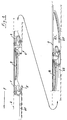
- the individual slats are labeled 1 to 3, with respect to the closed position shown in Closing direction, the direction of travel F in the embodiment corresponds, the foremost lamella bears the reference number 1, middle slat the reference number 2 and the rear slat the reference number 3.
- the top of the slats 1 to 3 is approximately flush with the roof contour 4, which is indicated by dashed lines, and they are over Appropriate guidance mechanisms in both sides of the roof opening lying, fixed to the roof at the ends of the slats Guide rails 5 guided, as schematized in Figure 1 are indicated by a double dash line.
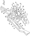
- Such a guide mechanism 6 comprises as can be seen in particular from FIGS. 9 and 10, in addition to the guide rail, not shown there, a guide carriage 7, on which two successive slats over their slat carriers 8 and 9 are supported, here only the lamella carrier 8 and 9 are shown, but not those on the back 10 of the slat carriers 8 and 9 slats each carried.
- Outgoing the slat carrier is of an assumed closing direction F. 8 assigned to a rear slat, which at Opening the lamella composite is first started, and the Lamellar support 9 in front of the closing direction F in front lying slat.
- the rear plate carrier 8 would be a lamella composite with several between the end lamellae lying slats, similar to the slat support 9, also supported on a guide carriage, in FIG. 9 the relevant carriage is shown and with 11 is designated, but the representation without the between the Guide carriage 11 and the disc carrier 8 lying parts the guide mechanism is done so that with respect to the guide carriage 7 and 11 only their position with respect to each other when the display is fully open Disc carrier 8 is illustrated.
- the carriage 11 a Central body 12, which in its rear end region carries a forked bracket 13 with fork arms 14 and 15 and laterally offset in the opposite direction to the central body 12 is provided with a boom 16 which is in the closing direction extends, and when the guide slides are moved towards each other in lateral overlap to the next guide carriage 7 lies.
- the boom 16 With identical construction of the guide carriages 11 and 7 the latter also has a boom 16, the boom 16 in length in relation to each other and to length of the central body 12 are dimensioned such that when colliding Carriage 7 and 11 between the arms 16 an engagement opening 17 results.
- the end faces that bound these the boom 16 are designated 50 and 51 and such beveled and inclined oppositely that the engagement opening 17 expands against the support surface of the boom 16. Due to the bevel, the end face 51 forms a ramp.
- the guide carriages carry, as for the guide carriage 11 can be seen in the area of their forked, raised console 13 at their opposite to each other with respect to the closing direction F. End regions pivot axes 18 and 19, of which the Pivot axis 18 the front in relation to the closing direction F. End area of the console 11 is assigned and as sled-fixed Axis of rotation for a plate carrier corresponding to the plate carrier 8 serves. This would come between the fork arms 14 and 15 to lie in the closed position of the slat corresponding position partially immersed between the fork arms 14 and 15. On the Pivot axis 19 with the console 13 is a control rocker 22 corresponding control rocker to store.
- the arms of the control rocker 22 are designated 20 and 21 and in relation to FIG Closing direction in front of the console 13 area over a Cross bridge are connected. Arms 20 and 21 of the control rocker 22 extend, as shown in FIG. 10, to the front area of the guide carriage, as for the guide carriage 7 recognizable, and they carry a guide pin in this area 23, which, as shown for the disk carrier 9 in FIG. 9, enforces this in the area of a guide link 24, which with slight curvature in the longitudinal direction of the disk carrier 9 extends.
- a corresponding guide link is for the disk carrier 8 25 indicated, the disk carrier and the Guide mechanisms for those lying between the end slats Slats of a laminated network are of the same design.
- the control rocker 22 is the carrier of a locking lever 26 Locking element 27.
- the locking element 27 comprises as a carrier the locking lever 26 a U-shaped bracket 28 in plan view, whose arms are designated 29 and 30 and in relation to the closing direction F is the foremost end region of the side view angular control rocker 22 on their arms 20 and 21st are stored.
- the relevant pivot axis is designated 31, and the arms 29 and 30 are connected by a web 32, on the respective plate carrier, here on the plate carrier 9 a guide is assigned, which by the Spine 10 on the opposite narrow side as guideway 33 and the end face 56 of the disk carrier 9 is formed.
- FIG. 10 also shows the respective guide carriage, here the guide carriage 7, associated guide body 34 to 36, which are formed by sliding blocks or the like can and of which the guide body 34 and 35 opposite to each other in relation to the closing direction End region, that is arranged approximately in the region of the console 13 are, while the guide body 36 in the region of the boom 16th is arranged.
- the respective guide carriage here the guide carriage 7, associated guide body 34 to 36, which are formed by sliding blocks or the like can and of which the guide body 34 and 35 opposite to each other in relation to the closing direction End region, that is arranged approximately in the region of the console 13 are, while the guide body 36 in the region of the boom 16th is arranged.
- support body 37 to 40 formed by support body 37 to 40 are, of which the support body 37 and 38 opposite Pages of the disk carrier 9 are assigned and in corresponding pivot positions of the control rocker 22 with support bodies 39 and 40 cover the arms 20 and 21 of the control rocker 22 assigned to the disk carrier 9 in their overlap area are and between the arms 20 and 21 and the plate carrier 9 lie.
- the support bodies 37 and 38 are preferably in between the guide track 33 and the guide link 24 horizontal web area 41 of the disk carrier 9 is provided, wherein in a further embodiment, the stop surfaces are also preferred between the support bodies 37 and 39 on the one hand and the Support bodies 38 and 40 on the other hand in different radial Distance to the guide pin 23, which is the guide link 24 penetrates and in the arms 20 and 21 of the control rocker 22nd is held. In this way, with only narrow contact surfaces, as they are only possible in the swivel direction for space reasons are able to achieve a sufficient degree of coverage.
- the mutual contact surfaces of the support bodies are in FIG 8 based on the front slats of the slat assembly in the closing direction shown and for those provided on the disk carrier Support body 37 and 38 designated 42 and 43, while the support bodies 39 and 40 assigned to the control rocker 22 Have contact surfaces 44 and 45.
- the support body 37 or 38 are preferably also opposite the control rocker 22 in the pivoting direction the disk carrier 9 staggered so that, with the lying on both sides of the disk carrier 9, through the support body 37 to 40 and their stop surfaces 42 to 45 are formed Stop pairs different, but in the locked position let overlapping engagement areas be realized.
- the coupling of the plate carrier 8 with the arms 20 and 21 of the Control rocker 22 is preferably carried out via a support pin 52 in the arms 20 and 21 of the control rocker 22 via corresponding Receiving holes is fixed and the plate carrier 8 in an elongated hole guide 53 (e.g. in Figure 8), so that Swiveling movements of the disk carrier 8 in swiveling movements the control rocker 22 are implemented, the elongated hole guide 53 caused by the offset of the pivot axes 18 and 19 Longitudinal offset of the support pin 52 with respect to the disk carrier 8 enables.
- elongated hole guide 53 e.g. in Figure 8
- Figures 1 to 8 illustrate the operation of the guide mechanism in connection with a slat roof
- the slat composite consists of three slats 1 to 3, of which the Slat 1 related to the closing direction F, in the embodiment corresponds to the direction of travel, foremost slat is.
- the slats 1 to 3 and those assigned to them Guiding devices in the closed position of the roof corresponding position shown, the top of the Slats 1 to 3 coincide approximately with the roof contour 4.
- Figure 4 shows a further intermediate position in the opening process of the roof, being for the slat 3 and the associated Management no changes compared to the state shown in Figure 2 have occurred since the end position is already shown in FIG is.
- slat 2 is a middle shift position in Figure 4 shown that based on the resolution of the pressure-resistant Support of the disk carrier 8 with respect to the control rocker 66 in Figure 2 is achieved in the further opening process when the previous guide carriage 61 almost the guide carriage 62 has reached and the boom 16 of the guide carriage 62, to that extent the guide carriage 11 in FIG. 9 corresponds to the overlap with the guide carriage 61, which corresponds to the guide carriage 7 in Figure 9.
- the pivot lever then overlaps the boom 16 and its web 32 in overlap with the slat carrier 9 of the slat 1, with the control rocker 22 via the corresponding stops is still supported rigidly.
- Figure 5 shows this enlarged, the reference symbols used in FIGS. 9 and 10 also are used here.
- Figure 6 shows the fully swung-out state also for the lamella 3, by moving the carriage further 60 and 61 is reached, the guide carriages 61 and 62 now overlap.
- a pressure-resistant support of the Disc carrier 9 given against the guide rocker 22, at least in the transition area in which the slat 2 is extended Has reached the end position and thus the shift the slat 1 compared to the slat 2 to continue the opening process a support must be released between the disk carrier 9 and the web 32 of the locking element 27 is superimposed so that the supporting forces between lamella 9 and Control rocker 22 when notching the associated contact surfaces 42 to 45 at least partially via the locking element 27 and its Web 32 are intercepted to excessive loads on the contact surfaces 40 to 45 especially in their edge areas, and to prevent premature wear.
- this is to be seen as an additional measure which, if necessary, in addition to the pressure support between the plate carrier and control rocker is appropriate.
- the roof closing process takes place in a corresponding manner, starting from the illustration according to FIG Guide carriage 60 comes into the position according to FIG. 6 the consequence that the locking element 27 due to the inclination of the Front side 50 is pushed out of its locked position.
- the locking element 27 may be acted upon accordingly is not shown here.
Landscapes
- Engineering & Computer Science (AREA)
- Mechanical Engineering (AREA)
- Fittings On The Vehicle Exterior For Carrying Loads, And Devices For Holding Or Mounting Articles (AREA)
- Body Structure For Vehicles (AREA)
Abstract
Description
- Figur 1
- eine schematisierte Darstellung des Lamellenverbundes eines Lamellendaches, über das bei geschlossenen Lamellen eine Dachöffnung abgedeckt ist, wobei die Lamellen beiderseits der Dachöffnung über im Bereich der Lamellenenden vorgesehene, nicht weiter dargestellte dachfeste Führungsschienen als Teile einer Führungsmechanik gefuhrt sind; die Dachkontur und die Führungsschienen sind nur angedeutet und der Lamellenverbund, der symmetrisch zur in Verschieberichtung des Lamellendaches verlaufenden Längsmittelebene aufgebaut ist, ist in einer Seitenansicht gezeigt,
- Figur 2
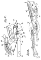
- eine der Figur 1 entsprechende Darstellung bei leicht geöffnetem Lamellendach, wobei die bezogen auf Fahrt- und Schließrichtung rückwärtige Lamelle ihre schräg nach hinten oben ausgestellte anschlaggesicherte Endstellung, geschoben durch den drucksteifen Verband der davor liegenden Lamellen, erreicht hat und die nächstfolgenden Lamellen in entsprechender Richtung leicht ausgestellt und geöffnet sind,
- Figur 3
- die vergrößerte Ausschnittsdarstellung des Bereiches III in Figur 2,
- Figur 4
- eine der Figur 1 entsprechende Darstellung in der Verschiebephase der nächstfolgenden Lamelle,
- Figur 5
- die vergrößerte Ausschnittsdarstellung des Bereiches V in Figur 4,
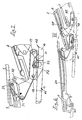
- Figur 6
- eine weitere der Figur 1 entsprechende Darstellung, bei der das Lamellendach gegenüber der Stellung gemäß Figur IV weiter geöffnet ist und die auf die rückwärtige Lamelle folgende Lamelle ihre volle Öffnungsstellung erreicht hat und die Verschiebung der nächstfolgenden Lamelle beginnt,
- Figur 7
- die Ausschnittsvergrößerung des Bereiches VII in Figur 6,
- Figur 8
- eine der Figur 1 entsprechende Darstellung des Lamellendaches in einer vollen Öffnungsstellung, wobei die Verrastung des der rückwärtigen Lamelle zugeordneten Führungsschlittens mit dem der mittleren Lamelle zugeordneten Führungsschlitten gezeigt ist, auf die Darstellung des den in Schließrichtung vordersten Führungsschlittens beaufschlagenden Stellantriebes aber verzichtet ist,
- Figur 9
- eine perspektivische Darstellung eines Teils der Führungsmechanik, wobei die den Führungsschlitten der Führungsmechanik aufnehmende Führungsschiene nicht gezeigt ist und eine Stellung zweier aufeinander folgender Lamellen angenommen ist, die etwa der in Figur 7 gezeigten entspricht, und
- Figur 10
- die Führungsmechanik ohne Führungsschiene in Draufsicht.
Claims (14)
- Lamellendach für eine Dachoffnung eines Kraftfahrzeuges mit zumindest zwei Lamellen (1 bis 3), die dachfest fixierbar sind und über eine Führungsmechanik (6) schienengeführt zwischen einer Schließstellung, in der sie die Dachöffnung abdeckend in einem flächigen Verbund angeordnet sind, und einer die Dachöffnung freigebenden Öffnungsstellung, in der sie einander teilweise schichtartig übergreifend schräg ausgestellt sind, beweglich sind, wobei die Führungsmechanik (6) mit Lamellenträger (8 bzw. 9) und Führungsschlitten (11) für einen Lamellenträger eine Abstützung auf zwei aufeinander folgenden Führungsschlitten (7 und 11) vorsieht, von denen zumindest einer - bezogen auf die Schließrichtung des Lamellendaches - eine Schwenkachse (18 bzw. 19) für den der hinteren Lamelle (3) zugehörigen Lamellenträger und in Verschieberichtung achsversetzt hierzu eine Schwenkachse für eine Steuerwippe (22) trägt, die aus ihrer dem geschlossenen Dach zugeordneten Grundstellung in eine das Ausstellen der Lamellen steuernde Funktionsstellung umsteuerbar ist und mit dem vor dem Führungsschlitten liegenden Lamellenträger über eine längs desselben verlaufende Führungskulisse (24 bzw. 25) verbunden ist,
dadurch gekennzeichnet,
daß die Steuerwippe (22) zumindest in Öffnungsrichtung der über sie abgestützten Lamelle (1 bis 3) in ihrer Schwenkbewegung mit dem bezogen auf die Schließrichtung (F) rückwärtigen Lamellenträger (8) zwangsgekoppelt ist. - Lamellendach nach Anspruch 1,
dadurch gekennzeichnet,
daß die Steuerwippe (22) in Öffnungs- und Schließrichtung in ihrer Schwenkbewegung mit dem bezogen auf die Schließrichtung rückwärtigen Lamellenträger (8) zwangsgekoppelt ist. - Lamellendach nach Anspruch 1 oder 2,
dadurch gekennzeichnet,
daß die Zwangskopplung von Steuerwippe (22) und Lamellenträger (8) über den gesamten Schwenkbereich vorgesehen ist. - Lamellendach nach einem der vorhergehenden Ansprüche,
dadurch gekennzeichnet,
daß bei zueinander versetzten Schwenkachsen (18 und 19) von Lamellenträger (8) und Steuerwippe (22)die Zwangskopplung zwischen Steuerwippe (22) und Lamellenträger (8) in einem wechselseitigen Übergriffsbereich vorgesehen ist. - Lamellendach nach einem der vorhergehenden Ansprüche,
dadurch gekennzeichnet,
daß die Schwenkachse (18) für den der hinteren Lamelle (3) zugeordneten Lamellenträger (8) gegenüber der Schwenkachse (19) der Steuerwippe (22) in Richtung auf den der vorderen Lamelle (1) zugeordneten Lamellenträger (9) versetzt liegt. - Lamellendach nach Anspruch 4 oder 5,
dadurch gekennzeichnet,
daß die Steuerwippe (22) im Bereich zwischen den Schwenkachsen (18 und 19) in Höhenrichtung gegenüber dem der hinteren Lamelle (3) zugeordneten Lamellenträger (8) abgestützt ist. - Lamellendach nach einem der vorhergehenden Ansprüche,
dadurch gekennzeichnet,
daß zur Koppelung von Steuerwippe (22) und Lamellenträger (8) ein Tragzapfen (52) vorgesehen ist, der in der Steuerwippe (22) oder im Lamellenträger (8) in einer Langlochführung (53) läuft. - Lamellendach nach Anspruch 7,
dadurch gekennzeichnet,
daß die Erstreckungsrichtung der Langlochführung (53) etwa der Erstreckung einer Verbindungsgeraden zwischen den Schwenkachsen (18 und 19) entspricht. - Lamellendach, insbesondere nach einem der vorhergehenden Ansprüche,
dadurch gekennzeichnet,
daß die mit dem bezogen auf die Schließrichtung (F) vor dem Führungsschlitten (7) liegenden Lamellenträger (9) über dessen in Längsrichtung desselben verlaufende Führungskulisse (24) verbundene Steuerwippe (22) im Bereich ihrer um die Schließlage gegebenen Grundstellung gegen zumindest eine dem Lamellenträger (9) zugeordnete Abstützung in Verschieberichtung drucksteif abgestützt ist. - Lamellendach nach Anspruch 9,
dadurch gekennzeichnet,
daß die Abstützung beiderseits des Steges des Lamellenträgers (9) liegende Stützkörper (37 und 38) umfaßt. - Lamellendach nach Anspruch 10,
dadurch gekennzeichnet,
daß die Stützkörper (37 und 38) in Längsrichtung des Lamellenträgers (9) gegeneinander versetzt sind. - Lamellendach nach einem der Ansprüche 9 bis 11,
dadurch gekennzeichnet,
daß der Abstützung zwischen Steuerwippe (22) und Lamellenträger (9) eine Abstützung über ein Sperrelement (27) überlagerbar ist, das in Abhängigkeit von der Stellung des bezogen auf die Schließrichtung jeweils rückwärtigen Lamellenträgers (8) gesteuert ist. - Lamellendach nach Anspruch 12,
dadurch gekennzeichnet,
daß das Sperrelement (27) in Richtung auf seine Abstützlage gegenüber dem Lamellenträger (9) federbelastet ist. - Lamellendach, insbesondere nach einem der Ansprüche 12 oder 13,
dadurch gekennzeichnet,
daß das Sperrelement (27) einen Sperrhebel (26) umfaßt, der an der Steuerwippe (22) gelagert ist und bei Verschieben des über die Steuerwippe aufstellbaren Lamellenträgers (9) gegenüber der Steuerwippe (22) über eine dem Lamellenträger (9) zugeordnete Führungsbahn (33) gefuhrt ist, derart, daß der Sperrhebel (27) über den die Steuerwippe (22) tragenden Führungsschlitten (7) in dessen der Offenstellung der über die Steuerwippe (22) aufgestellten Lamelle (9) entsprechenden Stellung relativ zu dem in Schließrichtung nächstfolgenden Führungsschlitten und/oder zu einer Führungsschiene festgelegt ist.
Applications Claiming Priority (2)
| Application Number | Priority Date | Filing Date | Title |
|---|---|---|---|
| DE19927654 | 1999-06-17 | ||
| DE19927654A DE19927654C1 (de) | 1999-06-17 | 1999-06-17 | Lamellendach für eine Dachöffnung eines Kraftfahrzeugs |
Publications (3)
| Publication Number | Publication Date |
|---|---|
| EP1060921A2 true EP1060921A2 (de) | 2000-12-20 |
| EP1060921A3 EP1060921A3 (de) | 2001-05-02 |
| EP1060921B1 EP1060921B1 (de) | 2003-08-20 |
Family
ID=7911558
Family Applications (1)
| Application Number | Title | Priority Date | Filing Date |
|---|---|---|---|
| EP00112279A Expired - Lifetime EP1060921B1 (de) | 1999-06-17 | 2000-06-08 | Lamellendach für eine Dachöffnung eines Kraftfahrzeugs |
Country Status (3)
| Country | Link |
|---|---|
| US (1) | US6502898B1 (de) |
| EP (1) | EP1060921B1 (de) |
| DE (2) | DE19927654C1 (de) |
Cited By (1)
| Publication number | Priority date | Publication date | Assignee | Title |
|---|---|---|---|---|
| EP1454783A1 (de) * | 2003-03-07 | 2004-09-08 | ArvinMeritor GmbH | Lamellen-Fahrzeugdach |
Families Citing this family (11)
| Publication number | Priority date | Publication date | Assignee | Title |
|---|---|---|---|---|
| DE10119701A1 (de) * | 2001-04-20 | 2002-10-31 | Cts Fahrzeug Dachsysteme Gmbh | Lamellendach |
| DE10119667A1 (de) * | 2001-04-20 | 2002-10-31 | Cts Fahrzeug Dachsysteme Gmbh | Lamellendach für Fahrzeuge |
| DE10154777A1 (de) * | 2001-11-08 | 2003-05-22 | Arvinmeritor Gmbh | Schiebesystem zum Verschliessen und Freigeben einer Dachöffnung |
| DE10202912C1 (de) * | 2002-01-25 | 2003-06-18 | Webasto Vehicle Sys Int Gmbh | Öffnungsfähiges Fahrzeugdach mit mindestens zwei verstellbaren Deckelelementen und einer dazwischen angeordneten Dichtungsanordnung |
| DE102004009049B4 (de) * | 2004-02-23 | 2005-11-17 | Cts Fahrzeug-Dachsysteme Gmbh | Fahrzeugdach mit mindestens zwei verstellbaren Dachteilen |
| DE102006000849B3 (de) | 2006-01-05 | 2007-08-02 | Magna Car Top Systems Gmbh | Dach für ein Kraftfahrzeug |
| US8177295B2 (en) * | 2009-11-20 | 2012-05-15 | AISIN Technical Center of America, Inc. | Dual panel sunroof |
| US9855828B1 (en) * | 2016-11-03 | 2018-01-02 | Tayih Kenmos Auto Parts Co., Ltd. | Tonneau cover |
| IT201700119592A1 (it) * | 2017-10-23 | 2019-04-23 | Opac Srl | Tetto retraibile. |
| DE102018108705A1 (de) * | 2018-04-12 | 2019-10-17 | Webasto SE | Anordnung und System für ein Fahrzeugdach sowie Verfahren zum Betreiben einer Anordnung für ein Fahrzeugdach |
| DE202018104521U1 (de) * | 2018-08-07 | 2019-11-12 | Inalfa Roof Systems Group B.V. | Offendachkonstruktion für ein Fahrzeug und damit versehenes Fahrzeug |
Family Cites Families (14)
| Publication number | Priority date | Publication date | Assignee | Title |
|---|---|---|---|---|
| US4357047A (en) | 1980-11-24 | 1982-11-02 | Strick Corporation | Trailer with unitary bottom rail-scuff plate |
| US4904017A (en) | 1985-02-26 | 1990-02-27 | Monon Corporation | Trailer construction |
| US4940279A (en) | 1989-03-16 | 1990-07-10 | Fruehauf Corporation | Cargo vehicle wall construction |
| DE4127624C1 (de) * | 1991-08-21 | 1992-09-24 | Webasto Ag Fahrzeugtechnik, 8035 Stockdorf, De | |
| US5509714A (en) | 1993-08-16 | 1996-04-23 | Strick Corporation | Frameless container for carrying cargo having overlapped sidewalls and a unitary bottom scuff panel |
| DE19529702C1 (de) * | 1995-08-11 | 1996-09-12 | Webasto Karosseriesysteme | Fahrzeugdach mit einer Folge von ausstellbaren Lamellen |
| DE19542884C1 (de) * | 1995-11-17 | 1996-12-12 | Webasto Karosseriesysteme | Fahrzeugdach mit einer Folge von ausstellbaren Lamellen |
| DE19608916C1 (de) * | 1996-03-07 | 1997-04-17 | Webasto Karosseriesysteme | Fahrzeugdach mit einer Folge von ausstellbaren Deckelelementen |
| US5664826A (en) | 1996-04-12 | 1997-09-09 | Wilkens; Arthur L. | Light weight trailer walls with smooth surfaces |
| US5860693A (en) | 1996-09-12 | 1999-01-19 | Wabash National Corporation | Composite joint configuration |
| DE19720822C1 (de) * | 1997-05-16 | 1999-03-11 | Daimler Benz Ag | Lamellendach für eine Dachöffnung eines Kraftfahrzeuges |
| NL1006925C2 (nl) * | 1997-09-03 | 1999-03-04 | Inalfa Ind Bv | Werkwijze voor het openen en sluiten van een open-dakconstructie van een voertuig met een opening in het vaste dak; alsmede een dergelijke open-dakconstructie. |
| US5938274A (en) | 1997-11-14 | 1999-08-17 | Wabash National Corporation | Coining offset into edge of composite plate members for forming trailer doors and walls |
| US5992117A (en) | 1998-01-12 | 1999-11-30 | Strick Corporation | Composite sidewall panels for cargo containers |
-
1999
- 1999-06-17 DE DE19927654A patent/DE19927654C1/de not_active Expired - Lifetime
-
2000
- 2000-06-08 EP EP00112279A patent/EP1060921B1/de not_active Expired - Lifetime
- 2000-06-08 DE DE50003338T patent/DE50003338D1/de not_active Expired - Lifetime
- 2000-06-19 US US09/597,712 patent/US6502898B1/en not_active Expired - Fee Related
Cited By (1)
| Publication number | Priority date | Publication date | Assignee | Title |
|---|---|---|---|---|
| EP1454783A1 (de) * | 2003-03-07 | 2004-09-08 | ArvinMeritor GmbH | Lamellen-Fahrzeugdach |
Also Published As
| Publication number | Publication date |
|---|---|
| DE19927654C1 (de) | 2000-07-20 |
| DE50003338D1 (de) | 2003-09-25 |
| EP1060921A3 (de) | 2001-05-02 |
| US6502898B1 (en) | 2003-01-07 |
| EP1060921B1 (de) | 2003-08-20 |
Similar Documents
| Publication | Publication Date | Title |
|---|---|---|
| EP0591644B1 (de) | Fahrzeugdach mit einer Folge von Lamellen | |
| DE19505006C1 (de) | Fahrzeugdach mit zwei Deckelelementen | |
| EP0670232B1 (de) | Fahrzeugdach mit einer Folge von Lamellen | |
| EP1060921B1 (de) | Lamellendach für eine Dachöffnung eines Kraftfahrzeugs | |
| EP0983196A1 (de) | Schleppfahrzeug für flugzeuge | |
| DE4127624C1 (de) | ||
| DE9412811U1 (de) | Sonnenschutzvorrichtung, insbesondere für lichtdurchlässige Sonnendächer | |
| DE2544110C3 (de) | Vorrichtung zum Auf- und Abladen eines Wagenkastens auf einem Fahrzeug | |
| EP0218020B1 (de) | Ausstell-Schiebedach für Kraftfahrzeuge | |
| DE3911165A1 (de) | Sitzverschiebe-vorrichtung | |
| DE69127909T2 (de) | Schiebe-Hebe-Dach-Vorrichtung für Kraftfahrzeug | |
| DE2938640A1 (de) | Schaltsteuereinrichtung fuer hydromechanische getriebe, insb. fuer ackerschlepper o.ae. nutzfahrzeuge | |
| CH623002A5 (en) | Railway goods wagon with multi-component sliding panel | |
| DE69622995T2 (de) | Öffnungsfähiges dach mit einem vorderen und einem hinteren, unabhängig betätigbaren, paneel | |
| DE19634324C2 (de) | Fahrzeugdach | |
| DE4329583C1 (de) | Fahrzeugdach mit einer Folge von Lamellen | |
| EP0309775A2 (de) | Ausstell-Schiebedach für Kraftfahrzeuge | |
| DE4329580C1 (de) | Fahrzeugdach mit einer Folge von Lamellen | |
| DE60009784T2 (de) | Konstruktion eines öffnungsfähigen Fahrzeugdaches | |
| DE69320036T2 (de) | Einziehbare einrichtung zum bedecken und öffnen eines zwei-oder dreidimensionalen platzes | |
| DE19720822C1 (de) | Lamellendach für eine Dachöffnung eines Kraftfahrzeuges | |
| EP0826538B1 (de) | Fahrzeugdach | |
| DE19856873C1 (de) | Lamellendach für eine Dachöffnung eines Kraftfahrzeugs | |
| EP1180445A1 (de) | Fahrzeugdach mit einem Schiebedeckel | |
| EP1071572A1 (de) | Verstellvorrichtung für ein multispoilerdach für fahrzeuge |
Legal Events
| Date | Code | Title | Description |
|---|---|---|---|
| PUAI | Public reference made under article 153(3) epc to a published international application that has entered the european phase |
Free format text: ORIGINAL CODE: 0009012 |
|
| AK | Designated contracting states |
Kind code of ref document: A2 Designated state(s): DE FR |
|
| AX | Request for extension of the european patent |
Free format text: AL;LT;LV;MK;RO;SI |
|
| PUAL | Search report despatched |
Free format text: ORIGINAL CODE: 0009013 |
|
| AK | Designated contracting states |
Kind code of ref document: A3 Designated state(s): AT BE CH CY DE DK ES FI FR GB GR IE IT LI LU MC NL PT SE |
|
| AX | Request for extension of the european patent |
Free format text: AL;LT;LV;MK;RO;SI |
|
| 17P | Request for examination filed |
Effective date: 20010516 |
|
| AKX | Designation fees paid |
Free format text: DE FR |
|
| GRAH | Despatch of communication of intention to grant a patent |
Free format text: ORIGINAL CODE: EPIDOS IGRA |
|
| GRAH | Despatch of communication of intention to grant a patent |
Free format text: ORIGINAL CODE: EPIDOS IGRA |
|
| GRAA | (expected) grant |
Free format text: ORIGINAL CODE: 0009210 |
|
| AK | Designated contracting states |
Designated state(s): DE FR |
|
| REF | Corresponds to: |
Ref document number: 50003338 Country of ref document: DE Date of ref document: 20030925 Kind code of ref document: P |
|
| ET | Fr: translation filed | ||
| PLBE | No opposition filed within time limit |
Free format text: ORIGINAL CODE: 0009261 |
|
| STAA | Information on the status of an ep patent application or granted ep patent |
Free format text: STATUS: NO OPPOSITION FILED WITHIN TIME LIMIT |
|
| 26N | No opposition filed |
Effective date: 20040524 |
|
| PGFP | Annual fee paid to national office [announced via postgrant information from national office to epo] |
Ref country code: FR Payment date: 20110711 Year of fee payment: 12 |
|
| PGFP | Annual fee paid to national office [announced via postgrant information from national office to epo] |
Ref country code: DE Payment date: 20110704 Year of fee payment: 12 |
|
| REG | Reference to a national code |
Ref country code: FR Ref legal event code: ST Effective date: 20130228 |
|
| REG | Reference to a national code |
Ref country code: DE Ref legal event code: R119 Ref document number: 50003338 Country of ref document: DE Effective date: 20130101 |
|
| PG25 | Lapsed in a contracting state [announced via postgrant information from national office to epo] |
Ref country code: FR Free format text: LAPSE BECAUSE OF NON-PAYMENT OF DUE FEES Effective date: 20120702 Ref country code: DE Free format text: LAPSE BECAUSE OF NON-PAYMENT OF DUE FEES Effective date: 20130101 |