EP1060940B1 - Abstandsbezogenes Fahrgeschwindigkeitsregelsystem - Google Patents
Abstandsbezogenes Fahrgeschwindigkeitsregelsystem Download PDFInfo
- Publication number
- EP1060940B1 EP1060940B1 EP00304980A EP00304980A EP1060940B1 EP 1060940 B1 EP1060940 B1 EP 1060940B1 EP 00304980 A EP00304980 A EP 00304980A EP 00304980 A EP00304980 A EP 00304980A EP 1060940 B1 EP1060940 B1 EP 1060940B1
- Authority
- EP
- European Patent Office
- Prior art keywords
- inter
- vehicle
- vehicle distance
- vehicular velocity
- target
- Prior art date
- Legal status (The legal status is an assumption and is not a legal conclusion. Google has not performed a legal analysis and makes no representation as to the accuracy of the status listed.)
- Expired - Lifetime
Links
- 238000000034 method Methods 0.000 title claims description 20
- 230000001276 controlling effect Effects 0.000 title 1
- 230000001105 regulatory effect Effects 0.000 title 1
- 230000004044 response Effects 0.000 claims description 83
- 238000013016 damping Methods 0.000 claims description 31
- 238000012545 processing Methods 0.000 description 13
- 238000010586 diagram Methods 0.000 description 10
- 238000001914 filtration Methods 0.000 description 9
- 230000005540 biological transmission Effects 0.000 description 8
- 230000003247 decreasing effect Effects 0.000 description 8
- 230000008569 process Effects 0.000 description 6
- 238000005259 measurement Methods 0.000 description 5
- 238000013459 approach Methods 0.000 description 4
- 230000006870 function Effects 0.000 description 3
- 230000010485 coping Effects 0.000 description 2
- 238000001514 detection method Methods 0.000 description 2
- 238000012986 modification Methods 0.000 description 2
- 230000004048 modification Effects 0.000 description 2
- 238000012546 transfer Methods 0.000 description 2
- 238000003491 array Methods 0.000 description 1
- 230000006399 behavior Effects 0.000 description 1
- 230000003111 delayed effect Effects 0.000 description 1
- 238000011161 development Methods 0.000 description 1
- 230000004069 differentiation Effects 0.000 description 1
- 230000000694 effects Effects 0.000 description 1
- 230000009467 reduction Effects 0.000 description 1
Images



Classifications
-
- B—PERFORMING OPERATIONS; TRANSPORTING
- B60—VEHICLES IN GENERAL
- B60W—CONJOINT CONTROL OF VEHICLE SUB-UNITS OF DIFFERENT TYPE OR DIFFERENT FUNCTION; CONTROL SYSTEMS SPECIALLY ADAPTED FOR HYBRID VEHICLES; ROAD VEHICLE DRIVE CONTROL SYSTEMS FOR PURPOSES NOT RELATED TO THE CONTROL OF A PARTICULAR SUB-UNIT
- B60W30/00—Purposes of road vehicle drive control systems not related to the control of a particular sub-unit, e.g. of systems using conjoint control of vehicle sub-units
- B60W30/14—Adaptive cruise control
- B60W30/16—Control of distance between vehicles, e.g. keeping a distance to preceding vehicle
-
- B—PERFORMING OPERATIONS; TRANSPORTING
- B60—VEHICLES IN GENERAL
- B60K—ARRANGEMENT OR MOUNTING OF PROPULSION UNITS OR OF TRANSMISSIONS IN VEHICLES; ARRANGEMENT OR MOUNTING OF PLURAL DIVERSE PRIME-MOVERS IN VEHICLES; AUXILIARY DRIVES FOR VEHICLES; INSTRUMENTATION OR DASHBOARDS FOR VEHICLES; ARRANGEMENTS IN CONNECTION WITH COOLING, AIR INTAKE, GAS EXHAUST OR FUEL SUPPLY OF PROPULSION UNITS IN VEHICLES
- B60K31/00—Vehicle fittings, acting on a single sub-unit only, for automatically controlling vehicle speed, i.e. preventing speed from exceeding an arbitrarily established velocity or maintaining speed at a particular velocity, as selected by the vehicle operator
- B60K31/0008—Vehicle fittings, acting on a single sub-unit only, for automatically controlling vehicle speed, i.e. preventing speed from exceeding an arbitrarily established velocity or maintaining speed at a particular velocity, as selected by the vehicle operator including means for detecting potential obstacles in vehicle path
-
- G—PHYSICS
- G05—CONTROLLING; REGULATING
- G05D—SYSTEMS FOR CONTROLLING OR REGULATING NON-ELECTRIC VARIABLES
- G05D1/00—Control of position, course, altitude or attitude of land, water, air or space vehicles, e.g. using automatic pilots
- G05D1/02—Control of position or course in two dimensions
- G05D1/021—Control of position or course in two dimensions specially adapted to land vehicles
- G05D1/0287—Control of position or course in two dimensions specially adapted to land vehicles involving a plurality of land vehicles, e.g. fleet or convoy travelling
- G05D1/0289—Control of position or course in two dimensions specially adapted to land vehicles involving a plurality of land vehicles, e.g. fleet or convoy travelling with means for avoiding collisions between vehicles
-
- B—PERFORMING OPERATIONS; TRANSPORTING
- B60—VEHICLES IN GENERAL
- B60W—CONJOINT CONTROL OF VEHICLE SUB-UNITS OF DIFFERENT TYPE OR DIFFERENT FUNCTION; CONTROL SYSTEMS SPECIALLY ADAPTED FOR HYBRID VEHICLES; ROAD VEHICLE DRIVE CONTROL SYSTEMS FOR PURPOSES NOT RELATED TO THE CONTROL OF A PARTICULAR SUB-UNIT
- B60W50/00—Details of control systems for road vehicle drive control not related to the control of a particular sub-unit, e.g. process diagnostic or vehicle driver interfaces
- B60W2050/0001—Details of the control system
- B60W2050/0019—Control system elements or transfer functions
- B60W2050/0022—Gains, weighting coefficients or weighting functions
-
- B—PERFORMING OPERATIONS; TRANSPORTING
- B60—VEHICLES IN GENERAL
- B60W—CONJOINT CONTROL OF VEHICLE SUB-UNITS OF DIFFERENT TYPE OR DIFFERENT FUNCTION; CONTROL SYSTEMS SPECIALLY ADAPTED FOR HYBRID VEHICLES; ROAD VEHICLE DRIVE CONTROL SYSTEMS FOR PURPOSES NOT RELATED TO THE CONTROL OF A PARTICULAR SUB-UNIT
- B60W50/00—Details of control systems for road vehicle drive control not related to the control of a particular sub-unit, e.g. process diagnostic or vehicle driver interfaces
- B60W2050/0001—Details of the control system
- B60W2050/0019—Control system elements or transfer functions
- B60W2050/0028—Mathematical models, e.g. for simulation
- B60W2050/0031—Mathematical model of the vehicle
-
- B—PERFORMING OPERATIONS; TRANSPORTING
- B60—VEHICLES IN GENERAL
- B60W—CONJOINT CONTROL OF VEHICLE SUB-UNITS OF DIFFERENT TYPE OR DIFFERENT FUNCTION; CONTROL SYSTEMS SPECIALLY ADAPTED FOR HYBRID VEHICLES; ROAD VEHICLE DRIVE CONTROL SYSTEMS FOR PURPOSES NOT RELATED TO THE CONTROL OF A PARTICULAR SUB-UNIT
- B60W2754/00—Output or target parameters relating to objects
- B60W2754/10—Spatial relation or speed relative to objects
- B60W2754/30—Longitudinal distance
Definitions
- the present invention relates to vehicular velocity controlling apparatus and method to follow up a preceding vehicle which is running ahead of the vehicle with an appropriate inter-vehicle distance maintained.
- a vehicular velocity controlling apparatus which controls vehicular velocity of an automotive vehicle to follow up a preceding vehicle which is running ahead of the vehicle.
- both an inter-vehicle distance command value (which corresponds to a target inter-vehicle distance in the previously proposed vehicular velocity controlling apparatus described above) and a target relative velocity are calculated from a target inter-vehicle distance (which corresponds to an inter-vehicle distance command value) using a filter prescribed by a damping factor ⁇ and a specific angular frequency ⁇ n, a vehicular velocity command value is calculated on the basis of a detected value of the vehicular velocity, a detected value of the relative velocity, a detected value of the inter-vehicle distance, and the target vehicular velocity, and the vehicular velocity is controlled to follow up the preceding vehicle on the basis of the vehicular velocity command value.
- the damping factor and the specific angular frequency used by a vehicular velocity command value calculating section are determined by referring to each previously set map (memory table) on the damping factor and the specific angular frequency to be used in an inter-vehicle distance control system according to the deviation between the detected (actual) inter-vehicle distance and the relative velocity of the vehicle to the preceding vehicle by means of a control response characteristic determining section.
- each of the maps is scheduled on a presupposition that the preceding vehicle is running at a constant cruise velocity. Hence, a mismatch to the driver's driving sense would occur when the preceding vehicle is decelerated to make a stop.
- vehicular braking force tends to be weak and the inter-vehicle distance becomes slowly widened since the specific angular frequency and the damping factor are set such that the response to the interruption of the preceding vehicle is delayed so that a slow convergence to the target inter-vehicle distance occurs on the presupposition that the preceding vehicle is running at the constant velocity (at the cruise speed). Hence, the mismatch to the driver's driving sense would occur.
- an object of the present invention to provide vehicular velocity controlling apparatus and method for an automotive vehicle which can achieve an appropriate follow-up run control to make the inter-vehicle distance appropriately equal to the target inter-vehicle distance without occurrence of the mismatch to the driver's driving sense even if the preceding vehicle is decelerated during the follow-up run control or the preceding vehicle is interrupted into the same traffic lane as the vehicle at a shorter inter-vehicle distance than the target inter-vehicle distance.
- DE 198 48 824 A discloses a vehicular velocity controlling apparatus according to the preambles of claims 1 and 13 respectively.
- the present invention provides a vehicular velocity controlling apparatus as set forth in claim 1.
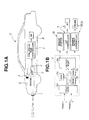
- Fig. 1A shows a schematic circuit block diagram of a vehicular velocity controlling apparatus in a preferred embodiment according to the present invention.
- a radar unit type inter-vehicle distance sensor 1 (simply, referred to as an inter-vehicle distance sensor) is disposed on a front end of the vehicle C to sweep a laser beam in a front width-wise direction (a front detection zone) of the vehicle C and receives a reflected laser beam from an object (namely, so-called, a preceding vehicle which is running ahead of the vehicle) present in the front width-wise direction.
- the inter-vehicle distance sensor 1 may measure the inter-vehicle distance to the trapped preceding vehicle utilizing an electric wave or ultrasonic wave.
- a rotational driving force developed on an engine E is transmitted through an automatic transmission T to drive wheels such as rear road wheels or front road wheels.
- a gear ratio of the automatic transmission T is controlled according to a vehicular velocity and an engine torque.
- a vehicular brake system B including a disc brake disposed on each road wheel is installed in the vehicle C.
- a vehicular velocity sensor 2 is attached onto an output axle of the automatic transmission (A/T) T.
- a pulse train signal having a period corresponding to a rotational velocity of the output axle of the automatic transmission T.
- a throttle actuator 3 is disposed in the engine E to actuate an engine throttle valve to be open or closed in accordance with a throttle valve opening angle signal inputted thereto so that an intake air quantity supplied to the engine E is varied to adjust an engine output.
- a follow-up run controller 5 controls the throttle actuator 3, the automatic transmission T, and the vehicular brake system B.
- the follow-up run controller 5 controls the throttle actuator 3, the automatic transmission T (gear ratio thereof), and the vehicular brake system B on the basis of the inter-vehicle distance L detected by the inter-vehicle distance sensor 1 and the vehicular velocity Vs of the vehicle C detected by the vehicular velocity sensor 2 so that the vehicle C can follow up the preceding vehicle, maintaining an appropriate inter-vehicle distance to the preceding vehicle.
- Fig. 1B shows an internal circuit configuration of the follow-up run controller 5 shown in Fig. 1A.
- the follow-up run controller 5 includes a microcomputer having a CPU (Central Processing Unit) 5a, a ROM (Read Only Memory) 5b, a RAM (Random Access Memory) 5c, a common bus, an Input Port 5e, and an Output Port 5d. It is noted that a timer is provided in the CPU 5a.
- CPU Central Processing Unit
- ROM Read Only Memory
- RAM Random Access Memory
- Fig. 2 shows a functional circuit block diagram of the vehicular velocity controlling apparatus shown in Fig. 1A.
- the follow-up run controller 5 functionally includes: a distance measurement signal processing section 21 that measures a time duration from a time point at which the laser light beam is swept from the inter-vehicle distance sensor 1 to a time point at which the reflected laser light beam is received thereat to calculate the inter-vehicle distance L to the preceding vehicle; a vehicular velocity signal processing section 22 that measures a period of the vehicular velocity indicative pulse train signal from the vehicular velocity sensor 13; a vehicular velocity signal processing section 30 that measures a period of a vehicular velocity pulse train signal to calculate a vehicular velocity Vs; an inter-vehicle distance controlling section 40 that calculates a target value of the vehicular velocity V* to maintain the inter-vehicle distance L at a target value of the inter-vehicle distance L* calculated by the distance measurement signal processing section 21 and the vehicular velocity Vs calculated by the vehicular velocity signal processing section 22; and a vehicular velocity controlling section 50 that controls the vehicular velocity Vs of the vehicle to make the detected value of the
- the inter-vehicle distance controlling section 40 includes a relative velocity calculating section 41 that calculates a relative velocity ⁇ V of the vehicle to the preceding vehicle inputted from the distance measurement signal processing section 20; a target inter-vehicle distance setting section 42 that calculates the target inter-vehicle distance L* between the preceding vehicle and the vehicular velocity on the basis of the vehicular velocity Vs inputted from the vehicular velocity signal processing section 30; an inter-vehicle distance command value calculating section 43 that calculates an inter-vehicle distance command value L T to make the actual inter-vehicle distance substantially equal to the target inter-vehicle distance L* between the preceding vehicle and the vehicle on the basis of the vehicular velocity Vs inputted from the vehicular velocity signal processing section 30; an inter-vehicle distance command value calculating section 43 that calculates the inter-vehicle distance command value L T to make the inter-vehicle distance L substantially equal to the target inter-vehicle distance L* through a reference model using a
- the relative velocity calculating section 41 is constituted by a band pass filter (BPF) which processes the inputted inter-vehicle distance L in a, e.g., band pass filter.
- BPF band pass filter
- the band pass filter has its transfer function that can be expressed in the following equation (1).
- ⁇ c 2 ⁇ fc
- s denotes a Laplace transform operator
- ⁇ c denotes a damping factor
- the band pass filter having the transfer function as given by the equation (1) is used as the relative velocity calculating section 41, the calculation of the relative velocity ⁇ V described above can avoid such an inconvenience case that is weak in a noise interference and that gives an ill influence on a vehicular dynamic (vehicular behavior) such as fluctuations occur in a vehicular body during the follow-up run control in a case where a simplified differential calculation is carried out from a variation rate of the inter-vehicle distance L so as to calculate the relative velocity ⁇ V.
- a cut-off frequency fc in the equation (1) is determined according to a magnitude of a noise component included in the inter-vehicle distance L and an allowance value of the vehicular body in a short period of time.
- the calculation of the relative velocity ⁇ V may alternatively be carried out by a differential process using a high pass filter to the inter-vehicle distance L in place of the band pass filter described above.
- the target inter-vehicle distance L* is set in such a manner that as the vehicular velocity becomes faster, the inter-vehicle distance becomes large.
- Ls denotes an initial inter-vehicle distance when the vehicle stops.
- the inter-vehicle distance calculating section 43 calculates the command value L T of the inter-vehicle distance on the basis of the actual inter-vehicle distance L, the target inter-vehicle distance L*, and the relative velocity ⁇ V to follow up the preceding vehicle maintaining the inter-vehicle distance L* in a second lag order form is carried out in accordance with a reference model G T (s) expressed in the equation of (3) using the damping factor ⁇ and the specific angular frequency ⁇ n determined for the response characteristic in the inter-vehicle distance system to be the target vehicular velocity so that the inter-vehicle distance command value V T is calculated.
- G T (s) ⁇ n 2 /(s 2 + 2 ⁇ ⁇ ns + ⁇ n)
- the target vehicular velocity calculating section 44 calculates the target vehicular velocity V* using a feedback compensator on the basis of the inputted inter-vehicle distance command value L T .
- the target relative velocity ⁇ V* is first calculated, as expressed in the following equation (4), by subtracting a linear connection between a value of a multiplication of a distance control gain fd and a deviation ⁇ L(L - L*) between the target inter-vehicle distance L* and the actual inter-vehicle distance L and a value of the multiplication of a velocity control gain fv with the relative velocity ⁇ V from a vehicular velocity of the preceding vehicle Vt of the preceding vehicle.
- ⁇ V* Vt - ⁇ fd(L T - L) + fv ⁇ V ⁇
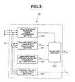
- Fig. 3 shows a detailed functional block diagram of the control response determining section 45 shown in Fig. 2.
- the specific angular frequency memory table representing the relationship between the deviation ⁇ L of the inter-vehicle distance (L - L*), the relative velocity ⁇ V, and the specific angular frequency ⁇ T in the inter-vehicle distance control system as shown in TABLE 1 to provide the optimum inter-vehicle distance control in various preceding vehicle follow-up run states, as shown in TABLE 1, is set to calculate the specific angular frequency ⁇ T in the inter-vehicle distance control system by referring to the memory table on the basis of the deviation ⁇ L on the inter-vehicle distance and the relative velocity ⁇ V.
- the specific angular frequency calculation memory table (map) is set and the specific angular frequency ⁇ T is calculated by referring to the memory table on the basis of the inter-vehicle distance deviation ⁇ L and the relative velocity ⁇ V.
- two quadrants in which the inter-vehicle distance deviation ⁇ L indicates negative value are set to provide the response characteristics for coping with the interruption of the preceding vehicle into the same traffic lane as the vehicle in front thereof and the remaining one of the quadrants (III quadrants) is set to provide the response characteristics for coping with a situation such that the preceding vehicle is far away from the vehicle and becomes separate from the vehicle.
- a plurality of specific angular frequency data ⁇ T are set to provide such a response characteristic that the actual inter-vehicle distance L is slowly converged into the target value of the inter-vehicle distance L*.
- the actual inter-vehicle distance L provides such a second-order response characteristic that the actual inter-vehicle distance L once overshoots or undershoots the target value of the inter-vehicle distance L* and converges into the target value thereof L*.
- Such a second-order response characteristic as described above can be achieved by means of the filter based on the equation (3) described above.
- the high response characteristic required determining section 454 determines that if L T > L and L T > L*, the present vehicular follow-up run state is the high response required state such as to have a possibility of decelerating the vehicle due to a preceding vehicle motion to stop the preceding vehicle itself. If, on the other hand, L* > L T > L, the high response required determining section 454 determines that the present vehicular follow-up run state is the high response required state such that the preceding vehicle has interrupted from the traffic lane to the same traffic lane as the vehicle at a shorter inter-vehicle distance than the target value of the inter-vehicle distance L*.
- a selection signal SS having, for example, a logical value of " 1 " is supplied to the selecting section 453.
- the selection signal SS having the logical value of " 0 " is supplied to the selecting section 453.
- the selecting section 453 selects the high response purpose specific angular frequency ⁇ nH set by the high response purpose specific angular frequency setting section 452 when the selection signal SS has the logical value of " 1 ".
- the specific angular frequency calculating section 451 is selected as the specific angular frequency ⁇ n.
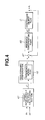
- Fig. 4 shows a block diagram of the inter-vehicle distance control system.
- a reference model 46 constituting the feed-forward compensator converts the target inter-vehicle distance L* calculated by the target inter-vehicle distance calculating section 42 into the inter-vehicle distance command value L T .
- a subtractor 47 subtracts the actual inter-vehicle distance L from the inter-vehicle distance command value LT. This deviation ⁇ L is converted into the target vehicular velocity V* by means of a feedback compensator 48 to control a controlled object 48 to control the controlled object C.
- Fig. 5 shows an operational flowchart of an inter-vehicle distance control procedure executed in the second preferred embodiment, namely, the follow up run controller shown in Fig. 1B
- the inter-vehicle distance control procedure is executed as a timer interrupt routine, (external interrupt by a timer) for each predetermined period of time (for example, 10 milliseconds) with respect to a main routine (not shown).
- the inter-vehicle distance control system i.e., the follow-up run controller 5 reads the actual inter-vehicle distance L calculated by the distance measurement signal processing section 21 and the vehicular velocity Vs converted by the vehicular velocity processing section 21.
- the inter-vehicle distance control system i.e., the follow-up run controller 5 performs the band pass filtering based on the equation (1) with respect to the actual inter-vehicle distance L to calculate the relative velocity ⁇ V and stores it into a relative velocity memory area to update the relative velocity ⁇ V. Then, the routine goes to a step S3.
- the calculated vehicular velocity of the preceding vehicle Vt is stored into a relative velocity memory area to update the stored value of the relative velocity value.
- the target inter-vehicle distance L* is calculated using the equation (2).
- the target inter-vehicle distance L* calculated at the step S4 and the relative velocity ⁇ V calculated at the step S2 are read.
- the inter-vehicle distance ⁇ L is calculated by subtracting the target inter-vehicle distance L from the actual inter-vehicle distance L.
- the follow-up run controller 5 refers to the specific angular frequency memory table shown in TABLE 1 and the damping factor calculation memory table shown in TABLE 2 on the basis of the relative velocity ⁇ V and the inter-vehicle distance deviation ⁇ L to calculate the specific angular frequency ⁇ T and the damping factor ⁇ .
- the calculated specific angular frequency ⁇ T and the damping factor ⁇ are stored into predetermined memory areas, respectively, to update them of the specific angular velocity and the damping factor.
- the follow-up run controller 5 determines if the preceding vehicle running state is under a predetermined control operation.
- the follow-up run controller 5 determines whether the present vehicle is under the braking operation. This determination is based on whether the target driving force F* calculated by the vehicular velocity controlling section 50 is smaller than a negative predetermined braking force threshold value TH B so that the vehicular brake system B is operated to effect the braking.
- the inter-vehicle distance control system determines that the vehicular brake system B is being operated so that the vehicle is not approaching to the preceding vehicle and the routine jumps to a step S8.
- the inter-vehicle distance control system performs the filtering in the equation (3) set at, for example, 0.5Hz of the cut-off frequency band on the specific angular frequency ⁇ n and the damping factor ⁇ stored in the specific angular frequency memory area and in the damping factor memory area with respect to the target inter-vehicle distance L* using the filtering process of the equation (3) set at, for example, 0.5 Hz to calculate the inter-vehicle distance command value L T .
- the calculated inter-vehicle distance command value L T is stored into an inter-vehicle distance command value memory area to update the stored inter-vehicle distance command value L T and the present routine goes to a step S9.
- step S9 the calculation of the equation (4) is performed and the target vehicular velocity V* is calculated to supply the value of V* to the vehicular velocity controlling section 50 and the present routine is ended to return to the main program routine.
- the inter-vehicle distance control system determines that the vehicle is approaching to the preceding vehicle and the routine goes to a step S10.
- the inter-vehicle distance control system determines whether the inter-vehicle distance command value L T is in excess of the actual inter-vehicle distance L. If L T > L, the routine goes to a step S11. At the step S11, the inter-vehicle distance control system determines that the present follow-up run state is not high response required state such that there is a possibility of decreasing the preceding vehicle to make a stop and the routine goes to a step S8.
- the follow up run controller 5 determines that the present follow-up run state is in the high response required state and the routine goes to a step S12.
- the inter-vehicle distance control system determines if the inter-vehicle distance command value L T is larger than the actual inter-vehicle distance L.
- the inter-vehicle distance control system determines that the present follow-up run state is the high response required state in which the preceding vehicle has interrupted from the other traffic lane to the same traffic lane as the vehicle at a shorter inter-vehicle distance than the target inter-vehicle distance L*.
- the step S2 corresponds to relative velocity detecting (calculating) means
- the step S4 corresponds to target inter-vehicle distance calculating means
- the steps S5 through S7 and S10 through S13 correspond to control response determining means
- the step S8 corresponds to the inter-vehicle distance command value calculating means
- the step S9 corresponds to the vehicular velocity calculating means.
- the vehicular velocity controlling section 50 calculates the driving force command value FoR and the disturbance estimated value dv' to make the target vehicular velocity approximately equal to the vehicular velocity Vs.
- the target driving force F* according to these deviations are calculated by means of the vehicular velocity according to these deviations are calculated by means of a vehicular velocity servo system.
- the vehicular velocity servo system is exemplified by United States Patent No. 5,919,572 issued on September 29, 1999, the disclosure of the above-described United States Patent being herein incorporated by reference.
- a vehicular velocity servo system using a robust model matching technique constituted by a robust compensator and a generally available feedback control system may be applied to the vehicular velocity servo system.
- the vehicular velocity controlling section 50 in the follow-up run controller 5 controls the throttle valve opening angle through the throttle actuator 3, the gear position of the automatic transmission A/T, and the braking force of the vehicular brake system B on the basis of the target driving force (vector variable) F* to make the inter-vehicle distance L substantially equal to the target inter-vehicle distance L* to perform the follow-up run control.
- the vehicle is running and maintaining at a constant vehicular velocity (cruise speed) which is the set vehicular velocity V SET by the vehicular driver with no preceding vehicle trapped and, thereafter, at a time point of t11 shown in Fig. 6 the vehicular velocity Vs of the vehicle is increased at a large relative velocity to the preceding vehicle which is running ahead of the vehicle at its constant velocity to catch up the preceding vehicle so that the preceding vehicle is trapped by the inter-vehicle distance sensor 1.
- a constant vehicular velocity (cruise speed) which is the set vehicular velocity V SET by the vehicular driver with no preceding vehicle trapped and, thereafter, at a time point of t11 shown in Fig. 6
- Vs of the vehicle is increased at a large relative velocity to the preceding vehicle which is running ahead of the vehicle at its constant velocity to catch up the preceding vehicle so that the preceding vehicle is trapped by the inter-vehicle distance sensor 1.
- the relative velocity ⁇ V indicates a negatively large value since the vehicle catches up (approach to) the preceding vehicle.
- the inter-vehicle distance L* calculated at the step S4 is based on the vehicular velocity Vt of the preceding vehicle so that the target value L* thereof indicates continuously a constant value and the specific angular frequency ⁇ T indicates 0.2 radian/sec at the step S6 and the damping factor ⁇ is set to about 0.1 thereat.
- the vehicular brake system 13 is under a non-operation state so that the routine shown in Fig. 5 jumps to the step S8 from the step S7 so that the filtering is executed on the basis of the specific angular frequency ⁇ T and the damping factor ⁇ set at the step S6 to derive the inter-vehicle distance command value L T .
- the actual inter-vehicle distance L 0 at a time point t11 at which the preceding vehicle is trapped is set.
- the initial value of L 0 is integrated so that the inter-vehicle distance command value L T provides a slow response characteristic and starts to be decreased at a moderate pace as denoted by a broken line of Fig. 6. Accordingly, the target vehicular velocity V* calculated at the step S9 becomes gradually smaller.
- the target driving force F* calculated by the vehicular velocity controlling section 50 maintains the positive value and is decreased at the moderate pace so that the throttle actuator 3 is controlled to close gradually the throttle valve of the engine E, the vehicular velocity Vs is decreased, and the actual inter-vehicle distance L is moderately decreased as denoted by a solid line of Fig. 6.
- the vehicular brake system B continues with the non-operation state.
- the inter-vehicle distance command value L T is continued to be calculated which provides a relatively slow response characteristic on the basis of the specific angular frequency ⁇ T and the damping factor ⁇ calculated on the basis of TABLE 1 and TABLE 2.
- the target vehicular velocity V* is reduced in order to make the actual inter-vehicle distance L approach to the inter-vehicle distance command value L T .
- the target driving force F* calculated by the vehicular velocity controlling section 50 is reduced and crosses zero to indicate a negative value at the time point t12.
- the vehicular brake system B is operated to be transferred to a moderate braking state.
- the routine goes form the step S7 to the step S10 in the timer interrupt routine of Fig. 5. Since, at the time point t12, the inter-vehicle distance command value L T is larger than the actual inter-vehicle distance L, the inter-vehicle distance control system determines that the present follow-up run state requires the high response characteristic and the routine shown in Fig. 5 goes to the step S12 to store the high response purpose specific angular frequency ⁇ nH into the specific angular frequency memory area as the updated specific angular frequency ⁇ n ( ⁇ n ⁇ nH). Hence, the response characteristic at the filtering executed at the step S8 is improved (or becomes higher (quicker)). Thereby, the calculated inter-vehicle distance command value L T is started to be decreased at a large gradient so that a quick convergence to the target inter-vehicle distance L* is advanced and, during this time duration, the moderate braking state is continued.
- the inter-vehicle distance command value L T is converged toward the target inter-vehicle distance L*.
- the vehicle is running at the constant velocity which corresponds to the set vehicular velocity (V SET ) and, at a time point of t21 in Fig. 7, the preceding vehicle whose relative velocity ⁇ V is small is interrupted from another traffic lane into the same traffic lane at a shorter inter-vehicle distance than the target inter-vehicle distance L* denoted by the dot-and-dash line of Fig. 7.
- the initial value of the filtering process at the step S8 in Fig. 5 is set to the actual inter-vehicle distance L 0 at the time point t22.
- the inter-vehicle distance command value L T is increased from the initial value L 0 with the relatively slow response characteristic, as denoted by the broken line of Fig. 7.
- the decrement variable of the target inter-vehicle distance V* calculated by the vehicular velocity controlling section 50 becomes small. Since the throttle opening angle is controlled in the close direction, the actual inter-vehicle distance L is increased moderately as denoted by the solid line of Fig. 7 but the vehicular brake system B is maintained at the non-operation state.
- the routine in Fig. 5 goes from the step S7 to the step S10. Since L T ⁇ L* (No) at the step S10, the routine in Fig. 5 goes to the step S13. Since L T > L (Yes) at the step S13, the inter-vehicle distance control system, i.e., the follow-up run controller 5 determines that the present follow-up run state is in the high response required state and the routine goes to the step S12.
- the filtering process is carried out at the step S8 so that the response characteristic is increased (becomes quicker). Consequently, the inter-vehicle distance command value L T is increased at a large gradient and the deviation between the inter-vehicle distance command value L T and the actual inter-vehicle distance L becomes accordingly large. Then, the target driving force F* indicates a negatively large value and the vehicular brake system B is controlled to develop a large braking force. Thus, the actual inter-vehicle distance L becomes speedily converged to the target inter-vehicle distance L*.
- the inter-vehicle distance control can be carried out without the mismatch to the driver's driving sense.
- the dot-and-dash line shown in Fig. 7 indicates the actual inter-vehicle distance L in the case where the actual inter-vehicle distance L is slowly increased due to the slow response characteristic in the previously proposed vehicular velocity control apparatus.
- the target driving force F* calculated by the vehicular velocity controlling section 50 is increased from the negative value to the vicinity to zero and in excess of the braking force threshold value TH B .
- the routine of Fig. 5 jumps from the step S7 to the step S8.
- the response characteristic of the inter-vehicle distance command value L T provides the original slow response characteristic as described above.
- the follow-up run controller 5 namely, the inter-vehicle distance control system determines that the present follow-up run state is in the high response required state and calculates the inter-vehicle distance command value L T with the high response characteristic based on the high response purpose specific angular frequency ⁇ nH which is larger than the normally used specific angular frequency data ⁇ T shown in TABLE 1.
- the deviation between the actual inter-vehicle distance and the inter-vehicle distance command value L T can be prevented from becoming larger. Consequently, the development of the large braking force can be suppressed.
- the relatively large braking force is developed so that the quick convergence of the actual inter-vehicle distance L to the target inter-vehicle distance L* can be achieved.
- a step S15 may be interposed between the steps S6 and S7 of Fig. 5 to determine, for example, if the relative velocity ⁇ V of the vehicle to the preceding vehicle is negative, namely, to determine if the vehicle is approaching to the preceding vehicle. If the vehicle is approaching to the preceding vehicle (Yes) at the step S15, the routine of Fig. 8 may go to the step S7. If the vehicle is not approaching to the preceding vehicle (No) at the step S15, the routine of Fig. 8 may jump to the step S8.
- the response characteristic may become high only when the high response characteristic is truly required (desired).
- the feed forward compensator may be constituted by the reference model 46 and a phase compensator 49 may calculate a compensated vehicular velocity command value V FF through the filter processing expressed in the following equation (5), the compensated vehicular velocity command value V FF being added to an output V FB of a feed back compensator 48 shown in Fig. 9.
- Gc(s) ⁇ ns(s + ⁇ v) ⁇ / ⁇ v(s 2 + 2 ⁇ ⁇ ns + ⁇ n) wherein ⁇ v denotes the specific angular frequency in the phase compensator 49.
- the specific angular frequency calculation memory table and the damping factor calculation memory table are used to calculate the specific angular frequency ⁇ T and the damping factor ⁇ .
- these frequency and factor may be calculated from corresponding characteristic equations.
- the follow-up run controller 5 executes the inter-vehicle distance calculating procedure
- a hardware of an electronic circuitry such as a combination of function generators, comparators, and arithmetic/logic unit may be applied.
- the present invention is applicable to the rear wheel drive vehicle as shown in Fig. 1A, however, the present invention may alternatively be applied to a front wheel drive vehicle.
- the present invention may be applied to an electric motor vehicle whose driving source is the electric motor or to a hybrid vehicle whose driving source is the electric motor or the engine.
Landscapes
- Engineering & Computer Science (AREA)
- Radar, Positioning & Navigation (AREA)
- Remote Sensing (AREA)
- Transportation (AREA)
- Mechanical Engineering (AREA)
- Automation & Control Theory (AREA)
- Aviation & Aerospace Engineering (AREA)
- Combustion & Propulsion (AREA)
- Chemical & Material Sciences (AREA)
- Physics & Mathematics (AREA)
- General Physics & Mathematics (AREA)
- Control Of Driving Devices And Active Controlling Of Vehicle (AREA)
- Controls For Constant Speed Travelling (AREA)
- Control Of Transmission Device (AREA)
- Control Of Vehicle Engines Or Engines For Specific Uses (AREA)
- Traffic Control Systems (AREA)
- Regulating Braking Force (AREA)
Claims (13)
- Fahrzeuggeschwindigkeits-Steuervorrichtung für ein selbstbewegendes Fahrzeug, umfassend:einen Fahrzeugszwischenabstandsdetektor (1, 5) zum Erfassen eines Fahrzeugszwischenabstands (L) von dem Fahrzeug zu einem vorangehenden Fahrzeug, das vor dem Fahrzeug fährt;einen Fahrzeuggeschwindigkeitsdetektor (2, 30) zum Erfassen einer Fahrzeuggeschwindigkeit (Vs) des Fahrzeugs;einen Relativgeschwindigkeitsdetektor (41) zum Erfassen einer Relativgeschwindigkeit (ΔV) des Fahrzeugs zu dem vorangehenden Fahrzeug;einen Zielfahrzeugzwischenabstands-Berechnungsabschnitt (42), der einen Zielfahrzeugzwischenabstand (L*) auf der Grundlage von erfassten Werten des Fahrzeugzwischenabstands (L) und der Fahrzeuggeschwindigkeit (Vs) berechnet;einen Steuerungsantwortcharakteristik-Bestimmungsabschnitt (45), der eine Steuerungsantwortcharakteristik eines Fahrzeugzwischenabstandssystems bestimmt;einen Fahrzeugzwischenabstands-Befehlswert-Berechnungsabschnitt (43), der einen Fahrzeugzwischenabstands-Befehlswert (LT) auf Grundlage des Zielfahrzeugzwischenabstands (L*) in Übereinstimmung mit der Steuerungsantwortcharakteristik berechnet;einen Zielfahrzeuggeschwindigkeits-Berechnungsabschnitt (44), der eine Zielfahrzeuggeschwindigkeit (V*) auf Grundlage des Fahrzeugzwischenabstands-Befehlswerts (LT) berechnet; undeinen Fahrzeuggeschwindigkeits-Steuerabschnitt (50), der die Zielfahrzeuggeschwindigkeit steuert, um den erfassten Wert der Fahrzeuggeschwindigkeit (VS) im Wesentlichen gleich zu der Zielfahrzeuggeschwindigkeit (V*) zu machen, dadurch gekennzeichnet, dass der Steuerungsantwortcharakteristik-Bestimmungsabschnitt (45) die Steuerungsantwortcharakteristik in Übereinstimmung mit einer Korrelation zwischen dem Zielfahrzeugzwischenabstand (L*), dem Fahrzeugzwischenabstands-Befehlswert (LT), und den erfassten Wert des Fahrzeugzwischenabstands (L) einstellt.
- Fahrzeuggeschwindigkeits-Steuervorrichtung für ein selbstbewegendes Fahrzeug nach Anspruch 1, wobei der Fahrzeugzwischenabstands-Befehlswert-Berechnungsabschnitt (43) den Fahrzeugzwischenabstands-Befehlswert (LT) auf Grundlage des Zielfahrzeugzwischenabstands (L*) unter Verwendung eines Referenzmodells, das durch einen Dämpfungsfaktor und eine spezifische Winkelfrequenz vorgeschrieben wird, berechnet, und wobei der Steuerungsantwortcharakteristik-Bestimmungsabschnitt (45) einschließt: einen Bestimmungsabschnitt für einen Zustand, der ein schnelles Ansprechverhalten erfordert, der bestimmt, dass das Fahrzeug dem vorangehenden Fahrzeug unter einem Zustand, der ein schnelles Ansprechverhalten erfordert, nachfolgt, aus der Korrelation unter dem Zielfahrzeugzwischenabstand (L*), dem Fahrzeugzwischenabstands-Befehlswert (LT), und dem erfassten Wert des Fahrzeugzwischenabstands (L); und einen Berechnungsabschnitt, der die spezifische Winkelfrequenz aus einer Speichertabelle für die spezifische Winkelfrequenz wählt, die eine Beziehung zwischen einer Abweichung des Zielfahrzeugzwischenabstands (L*) von dem erfassten Wert des Fahrzeugzwischenabstands (L), der relativen Geschwindigkeit (ΔV), und der spezifischen Winkelfrequenz darstellt, wenn der Bestimmungsabschnitt für die Charakteristik des schnellen Ansprechverhaltens bestimmt, dass das Fahrzeug fährt, um dem vorangehenden Fahrzeug bei einem Zustand, der kein schnelles Ansprechverhalten erfordert, nachfolgt, und der eine auf ein schnelles Ansprechverhalten zweckgebundene spezifische Winkelfrequenz (ωnH) wählt, wenn der Bestimmungsabschnitt für einen Zustand, der ein schnelles Ansprechverhalten erfordert, bestimmt, dass das Fahrzeug fährt, um dem vorangehenden Fahrzeug unter dem Zustand, der ein schnelles Ansprechverhalten erfordert, nachzufolgen.
- Fahrzeuggeschwindigkeits-Steuervorrichtung für ein selbstbewegendes Fahrzeug nach Anspruch 2, wobei der Bestimmungsabschnitt für einen Zustand, der ein schnelles Ansprechverhalten erfordert, bestimmt, dass das Fahrzeug fährt, um dem vorangehenden Fahrzeug bei dem Zustand, der ein schnelles Ansprechverhalten erfordert, nachfolgt, wenn der Fahrzeugzwischenabstands-Befehlswert (LT) größer als der erfasste Wert des Fahrzeugzwischenabstands (L) ist und größer als der Zielfahrzeugzwischenabstand (L*) ist.
- Fahrzeuggeschwindigkeits-Steuervorrichtung für ein selbstbewegendes Fahrzeug nach Anspruch 2, wobei der Bestimmungsanschnitt für einen Zustand, der ein schnelles Ansprechverhalten erfordert, bestimmt, dass das Fahrzeug fährt, um dem vorangehenden Fahrzeug bei dem Zustand, der ein schnelles Ansprechverhalten erfordert, nachfolgt, wenn der Fahrzeugzwischenabstand-Befehlswert (LT) kleiner als der Zielfahrzeugabstand (L*) ist und der erfasste Wert des Fahrzeugzwischenabstands (L) kleiner als der Fahrzeugzwischenabstands-Befehlswert (LT) ist.
- Fahrzeuggeschwindigkeits-Steuervorrichtung für ein selbstbewegendes Fahrzeug nach Anspruch 2, wobei der Wählabschnitt in die Lage versetzt wird, die auf ein schnelles Ansprechverhalten zweckgebundene spezifische Winkelfrequenz (ωnH) nur dann zu wählen, wenn das Fahrzeug sich dem vorangehenden Fahrzeug annähert.
- Fahrzeuggeschwindigkeits-Steuervorrichtung für ein selbstbewegendes Fahrzeug nach Anspruch 3, wobei die Größe der auf ein schnelles Ansprechverhalten zweckgebundenen spezifischen Winkelfrequenz (ωnH) größer als diejenige von jeden spezifischen Winkelfrequenzdaten (ωn), die in der Speichertabelle für die spezifische Winkelfrequenz gespeichert sind, ist.
- Fahrzeuggeschwindigkeits-Steuervorrichtung für ein selbstbewegendes Fahrzeug nach Anspruch 3, wobei der Fahrzeugzwischenabstands-Befehlswert-Berechnungsabschnitt (43) einen Dämpfungsfaktor-Berechnungsabschnitt einschließt, der den Dämpfungsfaktor auf Grundlage der Abweichung des Zielfahrzeugzwischenabstands von dem erfassten Wert des Fahrzeugzwischenabstands (ΔL = L - L*) und der Relativgeschwindigkeit (ΔV) aus einer Dämpfungsfaktor-Speichertabelle, die die Beziehung zwischen der Abweichung des Zielfahrzeugzwischenabstands und des erfassten Werts des Fahrzeugzwischenabstands darstellt, und der relativen Geschwindigkeit berechnet.
- Fahrzeuggeschwindigkeits-Steuervorrichtung für ein selbstbewegendes Fahrzeug nach Anspruch 7, wobei der Fahrzeuggeschwindigkeits-Steuerabschnitt (50) ein Fahrzeuggeschwindigkeits-Servosystem einschließt, das einen Antriebskraft-Befehlswert (FOR) und einen Störungs-abgeschätzten Wert (dv -) berechnet, um den erfassten Wert der Fahrzeuggeschwindigkeit (Vs) im Wesentlichen gleich zu der Zielfahrzeuggeschwindigkeit (V*) zu machen, und eine Zielfahrzeugantriebskraft (F*) berechnet, die eine Abweichung zwischen dem Antriebskraft-Befehlswert (FOR) und dem störungs-abgeschätzten Wert (dv -) ist, und wobei der Wählabschnitt einschließt: einen ersten Vergleicher, um die Zielfahrzeugantriebskraft (F*) mit einem Bremskraft-Schwellwert (THB) zu vergleichen, um zu bestimmen, ob F* ≤THB ist; einen zweiten Vergleicher zum Vergleichen des Fahrzeugzwischenabstands-Befehlswerts mit dem Zielfahrzeugzwischenabstand (L*), um zu bestimmen, ob LT > L* ist, wenn der erste Vergleicher bestimmt, dass F* ≤THB ist; einen dritten Vergleicher zum Vergleichen des Fahrzeugzwischenabstands-Befehlswerts (LT) mit dem erfassten Wert des Fahrzeugzwischenabstands (L), um zu bestimmen, ob LT > L ist, wenn der zweite Vergleicher bestimmt, dass LT > L* ist; einen vierten Vergleicher zum Vergleichen des Fahrzeugzwischenabstands-Befehlswerts (LT) mit dem erfassten Wert des Fahrzeugzwischenabstands (L) um zu bestimmen, ob LT > L ist, wenn der zweite Vergleicher bestimmt, dass LT ≤L* ist; und einen Einsteller, um die auf ein schnelles Ansprechverhalten zweckgebundene spezifische Winkelfrequenz (ωn (ωn ← ωnH)) einzustellen, wenn der dritte Vergleicher bestimmt, dass LT > L ist oder wenn der vierte Vergleicher bestimmt, dass LT > L ist.
- Fahrzeuggeschwindigkeits-Steuervorrichtung für ein selbstbewegendes Fahrzeug nach Anspruch 8, wobei der Fahrzeugzwischenabstands-Befehlswert-Berechnungsabschnitt (43) den Fahrzeugzwischenabstands-Befehlswert (LT) auf Grundlage der auf ein schnelles Ansprechverhalten zweckgebundenen spezifischen Winkelfrequenz (ωnH), die durch den Einsteller eingestellt wird, berechnet.
- Fahrzeuggeschwindigkeits-Steuervorrichtung für ein selbstbewegendes Fahrzeug nach Anspruch 9, wobei der Fahrzeugzwischenabstands-Befehlswert-Berechnungsabschnitt (43) den Zielfahrzeugzwischenabstands-Befehlswert (LT) auf der Grundlage der spezifischen Winkelfrequenz berechnet, wenn der erste Vergleicher bestimmt, dass F* > THB ist, wenn der dritte Vergleicher bestimmt, dass LT ≤L ist.
- Fahrzeuggeschwindigkeits-Steuervorrichtung für ein selbstbewegendes Fahrzeug nach Anspruch 9, wobei der Wählabschnitt ferner einen fünften Vergleicher einschließt, um die Relativgeschwindigkeit (ΔV) mit Null zu vergleichen, um zu bestimmen, ob sich das Fahrzeug grade dem vorangehenden Fahrzeug bei einer negativen Relativgeschwindigkeit annähert, und der Einsteller in die Lage versetzt wird die auf ein schnelles Ansprechverhalten zweckgebundene spezifische Winkelfrequenz als die spezifische Winkelfrequenz (ωn = ωnH) einzustellen, wenn der fünfte Vergleicher bestimmt, dass sich das Fahrzeug gerade dem vorangehenden Fahrzeug annähert.
- Fahrzeuggeschwindigkeits-Steuervorrichtung für ein selbstbewegendes Fahrzeug nach Anspruch 11, wobei die auf ein schnelles Ansprechverhalten zweckgebundene Winkelfrequenz (ωnH) ungefähr 0,5 Radiant/Sek. ist.
- Fahrzeuggeschwindigkeits-Steuerverfahren für ein selbstbewegendes Fahrzeug, umfassend die folgende Schritte.
Erfassen eines Fahrzeugzwischenabstands (L) von dem Fahrzeug zu einem vorangehenden Fahrzeug, das vor dem Fahrzeug fährt;
Erfassen einer Fahrzeuggeschwindigkeit (Vs) des Fahrzeugs;
Erfassen einer Relativgeschwindigkeit (ΔV) des Fahrzeugs zu dem vorangehenden Fahrzeug;
Berechnen eines Zielfahrzeugzwischenabstand (L*) auf Grundlage von erfassten Werten des Fahrzeugzwischenabstands (L) und der Fahrzeuggeschwindigkeit (VS);
Bestimmen einer Steuerungsantwortcharakteristik eines Fahrzeugzwischenabstandssystems;
Berechnen eines Fahrzeugzwischenabstands-Befehlswerts (LT) auf Grundlage des Zielfahrzeugzwischenabstands (L*) in Übereinstimmung mit der Steuerungsantwortcharakteristik;
Berechnen―einer Zielfahrzeuggeschwindigkeit (V*) auf Grundlage des Fahrzeugzwischenabstands-Befehlswerts (LT);
Steuern der Fahrzeuggeschwindigkeit, um den erfassten Wert der Fahrzeuggeschwindigkeit (Vs) im Wesentlichen gleich zu der Zielfahrzeuggeschwindigkeit (V*) zu machen, dadurch gekennzeichnet, dass die Steuerungsantwortcharakteristik in Übereinstimmung mit einer Kombination unter dem Zielfahrzeugzwischenabstand (L*), dem Fahrzeugzwischenabstands-Befehlswert (LT), und dem erfassten Wert des Fahrzeugzwischenabstands (L) eingestellt wird.
Applications Claiming Priority (2)
| Application Number | Priority Date | Filing Date | Title |
|---|---|---|---|
| JP16826699 | 1999-06-15 | ||
| JP16826699A JP3661496B2 (ja) | 1999-06-15 | 1999-06-15 | 先行車追従制御装置 |
Publications (3)
| Publication Number | Publication Date |
|---|---|
| EP1060940A2 EP1060940A2 (de) | 2000-12-20 |
| EP1060940A3 EP1060940A3 (de) | 2001-11-14 |
| EP1060940B1 true EP1060940B1 (de) | 2004-11-24 |
Family
ID=15864837
Family Applications (1)
| Application Number | Title | Priority Date | Filing Date |
|---|---|---|---|
| EP00304980A Expired - Lifetime EP1060940B1 (de) | 1999-06-15 | 2000-06-13 | Abstandsbezogenes Fahrgeschwindigkeitsregelsystem |
Country Status (4)
| Country | Link |
|---|---|
| US (1) | US6415217B1 (de) |
| EP (1) | EP1060940B1 (de) |
| JP (1) | JP3661496B2 (de) |
| DE (1) | DE60016090T2 (de) |
Families Citing this family (32)
| Publication number | Priority date | Publication date | Assignee | Title |
|---|---|---|---|---|
| JP3797115B2 (ja) * | 2001-02-15 | 2006-07-12 | 日産自動車株式会社 | 車速制御装置 |
| JP3788266B2 (ja) * | 2001-05-11 | 2006-06-21 | 日産自動車株式会社 | 車両用走行制御装置 |
| US7272482B2 (en) * | 2002-09-30 | 2007-09-18 | Nissan Motor Co., Ltd. | Preceding-vehicle following control system |
| JP4246084B2 (ja) * | 2004-02-17 | 2009-04-02 | 日産自動車株式会社 | 車両用走行制御装置 |
| JP4451315B2 (ja) * | 2005-01-06 | 2010-04-14 | 富士重工業株式会社 | 車両の運転支援装置 |
| US11207980B2 (en) * | 2005-11-17 | 2021-12-28 | Invently Automotive Inc. | Vehicle power management system responsive to traffic conditions |
| US11186174B2 (en) | 2005-11-17 | 2021-11-30 | Invently Automotive Inc. | Vehicle power management system |
| US11267339B2 (en) * | 2005-11-17 | 2022-03-08 | Invently Automotive Inc. | Vehicle power management system |
| US11267338B2 (en) * | 2005-11-17 | 2022-03-08 | Invently Automotive Inc. | Electric vehicle power management system |
| US11390165B2 (en) | 2005-11-17 | 2022-07-19 | Invently Automotive Inc. | Electric vehicle power management system |
| US11325468B2 (en) | 2005-11-17 | 2022-05-10 | Invently Automotive Inc. | Vehicle power management system |
| US11180025B2 (en) | 2005-11-17 | 2021-11-23 | Invently Automotive Inc. | Electric vehicle power management system |
| US11186173B2 (en) | 2005-11-17 | 2021-11-30 | Invently Automotive Inc. | Electric vehicle power management system |
| US11351863B2 (en) * | 2005-11-17 | 2022-06-07 | Invently Automotive Inc. | Vehicle power management system |
| US11247564B2 (en) | 2005-11-17 | 2022-02-15 | Invently Automotive Inc. | Electric vehicle power management system |
| US11186175B2 (en) | 2005-11-17 | 2021-11-30 | Invently Automotive Inc. | Vehicle power management system |
| US11225144B2 (en) | 2005-11-17 | 2022-01-18 | Invently Automotive Inc. | Vehicle power management system |
| US11285810B2 (en) | 2005-11-17 | 2022-03-29 | Invently Automotive Inc. | Vehicle power management system |
| US11254211B2 (en) | 2005-11-17 | 2022-02-22 | Invently Automotive Inc. | Electric vehicle power management system |
| US8712650B2 (en) | 2005-11-17 | 2014-04-29 | Invent.Ly, Llc | Power management systems and designs |
| US11279234B2 (en) | 2005-11-17 | 2022-03-22 | Invently Automotive Inc. | Vehicle power management system |
| US11214144B2 (en) | 2005-11-17 | 2022-01-04 | Invently Automotive Inc. | Electric vehicle power management system |
| US10882399B2 (en) | 2005-11-17 | 2021-01-05 | Invently Automotive Inc. | Electric vehicle power management system |
| US11220179B2 (en) | 2005-11-17 | 2022-01-11 | Invently Automotive Inc. | Vehicle power management system determining route segment length |
| US11207981B2 (en) | 2005-11-17 | 2021-12-28 | Invently Automotive Inc. | Vehicle power management system |
| US11230190B2 (en) | 2005-11-17 | 2022-01-25 | Invently Automotive Inc. | Electric vehicle power management system |
| US11084377B2 (en) | 2005-11-17 | 2021-08-10 | Invently Automotive Inc. | Vehicle power management system responsive to voice commands from a Gps enabled device |
| US11370302B2 (en) | 2005-11-17 | 2022-06-28 | Invently Automotive Inc. | Electric vehicle power management system |
| US11279233B2 (en) | 2005-11-17 | 2022-03-22 | Invently Automotive Inc. | Electric vehicle power management system |
| US11345236B2 (en) * | 2005-11-17 | 2022-05-31 | Invently Automotive Inc. | Electric vehicle power management system |
| KR100892539B1 (ko) | 2007-12-07 | 2009-04-09 | 현대자동차주식회사 | 차량의 차간거리 제어방법 |
| SE537482C2 (sv) * | 2013-09-30 | 2015-05-12 | Scania Cv Ab | Metod och system för gemensam körstrategi för fordonståg |
Family Cites Families (19)
| Publication number | Priority date | Publication date | Assignee | Title |
|---|---|---|---|---|
| JP2887948B2 (ja) | 1991-06-26 | 1999-05-10 | 株式会社デンソー | 車両用速度制御装置 |
| US5396426A (en) * | 1992-08-26 | 1995-03-07 | Nippondenso Co., Ltd. | Constant speed traveling apparatus for vehicle with inter-vehicle distance adjustment function |
| US5405655A (en) | 1992-11-19 | 1995-04-11 | Sri International | Temperature-resistant and/or nonwetting coatings of cured, silicon-containing polymers |
| JP3569926B2 (ja) * | 1993-03-03 | 2004-09-29 | 株式会社デンソー | 車両走行制御装置 |
| JP3060795B2 (ja) * | 1993-08-31 | 2000-07-10 | 三菱自動車工業株式会社 | 自動車の走行制御装置 |
| US5934399A (en) * | 1995-10-31 | 1999-08-10 | Honda Giken Kogyo Kabushiki Kaisha | Automatically driven motor vehicle |
| US5959572A (en) * | 1997-03-31 | 1999-09-28 | Nissan Motor Co., Ltd. | Vehicle follow-up control apparatus |
| US6223117B1 (en) * | 1997-05-27 | 2001-04-24 | General Motors Corporation | Cut-in management for an adaptive cruise control system |
| JP3518286B2 (ja) | 1997-10-23 | 2004-04-12 | 日産自動車株式会社 | 先行車追従制御装置 |
| US6188950B1 (en) * | 1997-10-27 | 2001-02-13 | Nissan Motor Co., Ltd. | System and method for controlling inter-vehicle distance to preceding vehicle for automotive vehicle equipped with the system and method |
| JPH11168266A (ja) | 1997-12-04 | 1999-06-22 | Hitachi Ltd | 印刷配線板上のバス配線方法 |
| JP3478107B2 (ja) * | 1998-01-14 | 2003-12-15 | 日産自動車株式会社 | 車両用走行制御装置 |
| JPH11278096A (ja) * | 1998-03-30 | 1999-10-12 | Nissan Motor Co Ltd | 車両用走行制御装置 |
| JP3551756B2 (ja) * | 1998-04-06 | 2004-08-11 | 日産自動車株式会社 | 車両用走行制御装置 |
| JP3651259B2 (ja) * | 1998-05-01 | 2005-05-25 | 日産自動車株式会社 | 先行車追従制御装置 |
| JP3690126B2 (ja) * | 1998-07-23 | 2005-08-31 | 日産自動車株式会社 | 車両用追従走行制御装置 |
| JP3661495B2 (ja) * | 1998-08-26 | 2005-06-15 | 日産自動車株式会社 | 先行車追従制御装置 |
| JP3606070B2 (ja) * | 1998-11-10 | 2005-01-05 | 日産自動車株式会社 | 車両用相対速度検出装置 |
| JP3960406B2 (ja) * | 1999-06-15 | 2007-08-15 | 日産自動車株式会社 | 先行車追従制御装置 |
-
1999
- 1999-06-15 JP JP16826699A patent/JP3661496B2/ja not_active Expired - Fee Related
-
2000
- 2000-06-12 US US09/592,567 patent/US6415217B1/en not_active Expired - Lifetime
- 2000-06-13 DE DE60016090T patent/DE60016090T2/de not_active Expired - Lifetime
- 2000-06-13 EP EP00304980A patent/EP1060940B1/de not_active Expired - Lifetime
Also Published As
| Publication number | Publication date |
|---|---|
| JP3661496B2 (ja) | 2005-06-15 |
| JP2000355235A (ja) | 2000-12-26 |
| DE60016090T2 (de) | 2005-11-24 |
| DE60016090D1 (de) | 2004-12-30 |
| EP1060940A2 (de) | 2000-12-20 |
| US6415217B1 (en) | 2002-07-02 |
| EP1060940A3 (de) | 2001-11-14 |
Similar Documents
| Publication | Publication Date | Title |
|---|---|---|
| EP1060940B1 (de) | Abstandsbezogenes Fahrgeschwindigkeitsregelsystem | |
| US6401024B1 (en) | Vehicle follow-up control system | |
| EP1061495B1 (de) | Vorrichtung und Verfahren zur Geschwindigkeits-und-Abstandsreglung eines Fahrzeugs | |
| US7054733B2 (en) | Adaptive cruise control system for vehicle | |
| EP1486370B1 (de) | Abstandsbezogenes Fahrgeschwindigkeitsregelsystem | |
| KR100275436B1 (ko) | 차량 추종 제어 장치 | |
| US6985805B2 (en) | Adaptive cruise control system | |
| US6405120B1 (en) | Vehicular velocity controlling apparatus and method to follow up a preceding vehicle running ahead of vehicle | |
| EP1075978B1 (de) | Soll-Drehmomenteinstellung für adaptive Geschwindigkeitsregelung eines Fahhrzeugs | |
| EP0982172B1 (de) | Abstandsbezogenes Fahrgeschwindigkeitsregelsystem für Kraftfahrzeuge | |
| US6256573B1 (en) | System and method for controlling inter-vehicle distance to preceding vehicle for automotive vehicle equipped with the system and method | |
| JP3690185B2 (ja) | 先行車追従制御装置 | |
| JPH11291788A (ja) | 車両用走行制御装置 | |
| KR20170032854A (ko) | 차량의 제어 장치 및 추종 주행 시스템 | |
| US6870468B2 (en) | Adaptive cruise speed controlling apparatus and method for automotive vehicle | |
| EP1060937B1 (de) | Abstandsbezogene Fahrgeschwindigkeitsregelung bei Kurvenfahrt | |
| JP4161822B2 (ja) | 追従走行制御装置 | |
| JP3767353B2 (ja) | 車両用追従走行制御装置 | |
| JP2002079846A (ja) | 先行車追従制御装置 | |
| JP4060421B2 (ja) | 車間距離制御装置 | |
| JP4622414B2 (ja) | 走行制御装置 | |
| JP2004155423A (ja) | 車両用追従走行制御装置 |
Legal Events
| Date | Code | Title | Description |
|---|---|---|---|
| PUAI | Public reference made under article 153(3) epc to a published international application that has entered the european phase |
Free format text: ORIGINAL CODE: 0009012 |
|
| 17P | Request for examination filed |
Effective date: 20000712 |
|
| AK | Designated contracting states |
Kind code of ref document: A2 Designated state(s): AT BE CH CY DE DK ES FI FR GB GR IE IT LI LU MC NL PT SE Kind code of ref document: A2 Designated state(s): DE FR GB |
|
| AX | Request for extension of the european patent |
Free format text: AL;LT;LV;MK;RO;SI |
|
| PUAL | Search report despatched |
Free format text: ORIGINAL CODE: 0009013 |
|
| AK | Designated contracting states |
Kind code of ref document: A3 Designated state(s): AT BE CH CY DE DK ES FI FR GB GR IE IT LI LU MC NL PT SE |
|
| AX | Request for extension of the european patent |
Free format text: AL;LT;LV;MK;RO;SI |
|
| AKX | Designation fees paid |
Free format text: DE FR GB |
|
| 17Q | First examination report despatched |
Effective date: 20030606 |
|
| GRAP | Despatch of communication of intention to grant a patent |
Free format text: ORIGINAL CODE: EPIDOSNIGR1 |
|
| GRAS | Grant fee paid |
Free format text: ORIGINAL CODE: EPIDOSNIGR3 |
|
| GRAA | (expected) grant |
Free format text: ORIGINAL CODE: 0009210 |
|
| AK | Designated contracting states |
Kind code of ref document: B1 Designated state(s): DE FR GB |
|
| REG | Reference to a national code |
Ref country code: GB Ref legal event code: FG4D |
|
| REF | Corresponds to: |
Ref document number: 60016090 Country of ref document: DE Date of ref document: 20041230 Kind code of ref document: P |
|
| PLBE | No opposition filed within time limit |
Free format text: ORIGINAL CODE: 0009261 |
|
| STAA | Information on the status of an ep patent application or granted ep patent |
Free format text: STATUS: NO OPPOSITION FILED WITHIN TIME LIMIT |
|
| 26N | No opposition filed |
Effective date: 20050825 |
|
| ET | Fr: translation filed | ||
| REG | Reference to a national code |
Ref country code: FR Ref legal event code: PLFP Year of fee payment: 17 |
|
| REG | Reference to a national code |
Ref country code: FR Ref legal event code: PLFP Year of fee payment: 18 |
|
| REG | Reference to a national code |
Ref country code: FR Ref legal event code: PLFP Year of fee payment: 19 |
|
| PGFP | Annual fee paid to national office [announced via postgrant information from national office to epo] |
Ref country code: DE Payment date: 20190528 Year of fee payment: 20 |
|
| PGFP | Annual fee paid to national office [announced via postgrant information from national office to epo] |
Ref country code: FR Payment date: 20190510 Year of fee payment: 20 |
|
| PGFP | Annual fee paid to national office [announced via postgrant information from national office to epo] |
Ref country code: GB Payment date: 20190612 Year of fee payment: 20 |
|
| REG | Reference to a national code |
Ref country code: DE Ref legal event code: R071 Ref document number: 60016090 Country of ref document: DE |
|
| REG | Reference to a national code |
Ref country code: GB Ref legal event code: PE20 Expiry date: 20200612 |
|
| PG25 | Lapsed in a contracting state [announced via postgrant information from national office to epo] |
Ref country code: GB Free format text: LAPSE BECAUSE OF EXPIRATION OF PROTECTION Effective date: 20200612 |