EP1061014B1 - Tête de préhension pour saisir, manipuler et libérer des objets de dimensions différentes - Google Patents
Tête de préhension pour saisir, manipuler et libérer des objets de dimensions différentes Download PDFInfo
- Publication number
- EP1061014B1 EP1061014B1 EP00111237A EP00111237A EP1061014B1 EP 1061014 B1 EP1061014 B1 EP 1061014B1 EP 00111237 A EP00111237 A EP 00111237A EP 00111237 A EP00111237 A EP 00111237A EP 1061014 B1 EP1061014 B1 EP 1061014B1
- Authority
- EP
- European Patent Office
- Prior art keywords
- take
- jaws
- head according
- articulated
- head
- Prior art date
- Legal status (The legal status is an assumption and is not a legal conclusion. Google has not performed a legal analysis and makes no representation as to the accuracy of the status listed.)
- Expired - Lifetime
Links
- 230000010355 oscillation Effects 0.000 claims abstract description 5
- 239000000463 material Substances 0.000 claims description 3
- 238000012856 packing Methods 0.000 claims description 3
- 230000008878 coupling Effects 0.000 description 1
- 238000010168 coupling process Methods 0.000 description 1
- 238000005859 coupling reaction Methods 0.000 description 1
- 229920001971 elastomer Polymers 0.000 description 1
- 230000005484 gravity Effects 0.000 description 1
- 238000004519 manufacturing process Methods 0.000 description 1
- 238000012986 modification Methods 0.000 description 1
- 230000004048 modification Effects 0.000 description 1
- 229920002635 polyurethane Polymers 0.000 description 1
- 239000004814 polyurethane Substances 0.000 description 1
Images
Classifications
-
- B—PERFORMING OPERATIONS; TRANSPORTING
- B65—CONVEYING; PACKING; STORING; HANDLING THIN OR FILAMENTARY MATERIAL
- B65G—TRANSPORT OR STORAGE DEVICES, e.g. CONVEYORS FOR LOADING OR TIPPING, SHOP CONVEYOR SYSTEMS OR PNEUMATIC TUBE CONVEYORS
- B65G17/00—Conveyors having an endless traction element, e.g. a chain, transmitting movement to a continuous or substantially-continuous load-carrying surface or to a series of individual load-carriers; Endless-chain conveyors in which the chains form the load-carrying surface
- B65G17/30—Details; Auxiliary devices
- B65G17/32—Individual load-carriers
- B65G17/323—Grippers, e.g. suction or magnetic
-
- B—PERFORMING OPERATIONS; TRANSPORTING
- B65—CONVEYING; PACKING; STORING; HANDLING THIN OR FILAMENTARY MATERIAL
- B65G—TRANSPORT OR STORAGE DEVICES, e.g. CONVEYORS FOR LOADING OR TIPPING, SHOP CONVEYOR SYSTEMS OR PNEUMATIC TUBE CONVEYORS
- B65G2201/00—Indexing codes relating to handling devices, e.g. conveyors, characterised by the type of product or load being conveyed or handled
- B65G2201/02—Articles
Definitions
- the invention relates to a take-up head for the grasping, movement and release of objects of diverse shape, particularly suitable for automatic packing machines.
- the present invention relates to a take-up head of the above-mentioned type, particularly suitable for a conveyor/distributor system of objects of the closed loop type equipped with continuous motion, which is intended to grasp, in a take-up station, the objects disposed aligned along a longitudinal feed row, then to move them and distribute them methodically along two or more longitudinal rows transversely spaced apart which move them away, and then release them in a release station.
- -A first disadvantage is due to the fact that they require the presence of a lower conveyor and an upper conveyor, as well as the presence of synchronization means intended to keep the lower take-up devices vertically aligned with the respective upper take-up devices, comprising the production of a complex and costly system which is difficult to manage.
- the said take-up devices do not ensure a reliable (positive) take-up of the object to be moved, they are not capable of operating with specific objects such as flexible bags and/or boxes and/or similar objects, and are not suitable for operating with diverse shapes of objects, i.e. they are not very flexible.
- the said take-up heads do not enable objects such as bags and/or boxes and/or similar objects, i.e. objects not fitted with caps, to be handled.
- the object of the present invention is to remedy the above-mentioned disadvantages.
- the invention which is characterized by the claims, solves the problem of creating a take-up head for the grasping, movement and release of objects of diverse shape particularly suitable for automatic packing machines in that the said take-up head is characterized in that it comprises: -a support body associated with conveying means for the movement of the said body; -a first articulated linkage having a frame carried by the said support body and a respective connecting rod intended to carry a first jaw; -a second articulated linkage having a frame carried by the said support body and a respective connecting rod intended to carry a second jaw, both disposed in mirror fashion and opposed with respect to the said first linkage and the said first jaw, and control means suitable for controlling the oscillation in opening of said two jaws of the said two articulated linkages.
- the advantages obtained by means of the present invention substantially consist of the fact that the said take-up head does not have to be replaced when the shape of the objects to be distributed changes; that the objects are not damaged during distribution as a result of impacts; and that the productive capacity per unit of time of the relative distribution system is increased.
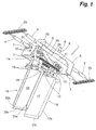
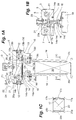
- the take-up head to which the invention relates is intended to be transported in known manner by means of a pair of chains 2a and 2b, which carry the ends of two transverse rods 3 and 4, in which the rod denoted by 3 couples in sliding manner with a precision bush 5 fixed to a box-type support body denoted by 6, see also Fig. 1B, and the rod denoted by 4 couples with play in sliding manner inside square holes denoted by 7 and produced in the support body 6.
- the support body 6 takes the form of a containment box open at the bottom, to the top of which is fixed a pin 8 fitted with a roller 9, the latter intended to cooperate with a known longitudinal guide way 10, see Fig. 1A, disposed along the distribution path, for the purpose of disposing the said support body 6 in an accurate transverse position during its longitudinal travel along the said path.
- the same support body 6 internally comprises a crosspiece 11 which is fixed to the body 6 by means of screws 12 and carries, in proximity to its end portions, see Figs. 1 and 1A, two distinct articulated linkages, in particular two four-bar linkages, denoted by 13 and 14, disposed in mirror fashion and opposed with respect to each other, in which the first articulated linkage 13 has four rotoidal pairs (hinges) 13a, 13b, 13c and 13d intended to form a frame 13a-13b obtained in the crosspiece 11, an internal rocker arm 13a-13c, an external rocker arm 13b-13d, and a connecting rod 13c-13d formed by two pairs of counterfacing blocks denoted by 15, in which these latter carry in fixed manner a jaw 16 which has a grasping face 17 with inclined edges 17a, 17b and 17c, see also Fig.
- the second articulated linkage 14 has four rotoidal pairs (hinges) 14a, 14b, 14c and 14d, intended to form a frame 14a-14b obtained in the crosspiece 11, an internal rocker arm 14a-14c, an external rocker arm 14b-14d and a connecting rod 14c-14d formed by two pairs of counterfacing blocks denoted by 18, in which these latter carry in fixed manner a jaw 19 which has a grasping face 20 with inclined edges 20a, 20b and 20c, see also Fig. 1C.
- the take-up head 1 is provided with control means suitable for controlling the oscillation in opening of said jaws 16 and 19 of the said two articulated linkages 13 and 14 as described hereinafter.
- the internal rocker arm 14a-14c of the second articulated linkage 14 has a longitudinal extension 21, extending beyond the said box-type support body 6 and passing freely through a slot 22, in which at its free upper end the said extension has a roller 23 intended to cooperate with a longitudinal cam profile 24 disposed along the feed path of the said head 1, for the purpose of causing the said extension 21 and the relative rocker arm 14a-14c to oscillate on command in the direction shown by the arrow F1 as described in more detail below.
- the said extension 21 carries an end of an interconnection element 25 which has its opposite end hinged in 25b on the internal rocker arm 13a-13c of the first articulated linkage 13.
- the two external rocker arms, 14b-14d and 13b-13d are interconnected by means of resilient means which apply traction, such as, for example, one or two tension springs 26 disposed on the two opposite sides of the said external rocker arms 14b-14d and 13b-13d, for the purpose of causing the said two external rocker arms 14b-14d and 13b-13d to approach reciprocally and, consequently, bringing the jaws 16 and 19 into a position of approach/closure.
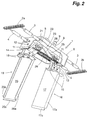
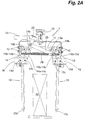
- the device 1 is disposed above the object 30 to be grasped with the jaws 16 and 19 in open position and with the springs 26 under tension, in that the said configuration is actuated by means of the roller 23 which slides on the longitudinal cam profile 24.
- steps are taken to modify and/or interrupt the longitudinal cam profile 24 on which the roller 23 slides, and the jaws 16 and 19, under the action of the springs 26, see Fig. 1A, are caused to approach reciprocally, with consequent grasping of the object 30.
- the grasping walls 17 and 20 of the jaws 16 and 19 may be coated with flexible material, such as polyurethane and/or rubber and/or another flexible material which has a high coefficient of friction, so as to permit a better hold of the object.
- flexible material such as polyurethane and/or rubber and/or another flexible material which has a high coefficient of friction, so as to permit a better hold of the object.
- the springs 26 which provide to cause the jaws 16 and 19 to approach each other again for grasping, and which therefore also determine the tightening force of the jaws 16 and 19 may easily be replaced, for the purpose of employing springs suitable for exerting a desired tightening force such as not to damage the object to be grasped but still permitting sufficient hold.
Landscapes
- Engineering & Computer Science (AREA)
- Mechanical Engineering (AREA)
- Wrapping Of Specific Fragile Articles (AREA)
- Manipulator (AREA)
- Load-Engaging Elements For Cranes (AREA)
- Testing Of Coins (AREA)
- Measurement Of Length, Angles, Or The Like Using Electric Or Magnetic Means (AREA)
- Geophysics And Detection Of Objects (AREA)
Claims (10)
- Tête de préhension pour saisir, déplacer et libérer des objets de diverses formes en particulier appropriée pour les machines de conditionnement automatiques,
comprenant :un corps de support (6-11) ;un premier élément de liaison articulé (13) ayant un cadre (13a-13b) porté par ledit corps de support (11) et une tige de liaison respective (13c-13d, 15) destinée à porter une première mâchoire (16) ;un second élément de liaison articulé (14) ayant un cadre (14a-14b) porté par ledit corps de support (11) et une tige de liaison respective (14c-14d, 18) destinée à porter une seconde mâchoire (19), disposée à la fois en miroir et en opposition par rapport audit premier élément de liaison (13) et à ladite première mâchoire (16) ; caractérisée en ce qu'elle comprend :des moyens de commande (23, 21, 25, 26) adaptés pour commander l'oscillation d'ouverture desdites -deux mâchoires (16, 19) desdits deux moyens de liaison articulés (13, 14), et en ce que ledit corps de support est adapté pour être associé avec des moyens de déplacement (3, 4, 9, 10) pour le déplacement dudit corps de support (6-11). - Tête de préhension selon la revendication 1, caractérisée en ce que lesdits premier (13) et second (14) moyens de liaison articulés sont deux moyens de liaison à quatre barres (13a, 13b, 13c, 13d, 13a-13b, 13a-13c, 13b-13d, 13c-13d/14a, 14b, 14c, 14d, 14a-14b, 14a-14c, 14b-14d, 14c-14d).
- Tête de préhension selon l'une des revendications précédentes, caractérisée en ce que la surface de préhension (17, 20) desdites mâchoires de préhension (16, 19) est couverte avec un matériau spécifique sélectionné en fonction de l'objet à manipuler.
- Tête de préhension selon l'une des revendications précédentes, caractérisée en ce que lesdites mâchoires (16, 19) ont une longueur choisie de façon à venir en contact du corps des objets (30) jusqu'à proximité de leur base ou jusqu'à un niveau légèrement au-dessus.
- Tête de préhension selon l'une des revendications précédentes, caractérisée en ce que lesdites mâchoires (16, 19) ont des faces de préhension (17, 20) avec des bords inclinés (17a-17b-17c, 20a-20b-20c) qui forment un chanfrein "d'invitation" pour faciliter la disposition des parois correctement le long de l'objet (30) à prendre.
- Tête selon l'une des revendications précédentes, caractérisée en ce qu'on prévoit des moyens élastiques (26) appropriés pour amener lesdites deux mâchoires (16, 19) en position d'approche réciproque.
- Tête selon la revendication 6, caractérisée en ce que lesdits moyens élastiques (26) comprennent au moins un ressort (26) destiné à créer une force de tension entre deux bras de pivotement (14b-14d, 13b-13d) des deux moyens de liaison articulés distincts (13, 14) dans le but d'amener les mâchoires (16, 19) en une position de fermeture.
- Tête selon l'une des revendications précédentes, caractérisée en ce que lesdits moyens de commande comprennent une extension longitudinale (21) d'un bras de pivotement (14a-14c) de l'un (14) desdits deux moyens de liaison et en ce que à son extrémité libre supérieure ladite extension comprend un galet (23) destiné à coopérer avec un profil de came (24) disposé le long du chemin d'alimentation de ladite tête (1).
- Tête selon l'une des revendications précédentes, caractérisée en ce que des moyens d'interconnexion (25) sont prévus entre ledit premier élément de liaison articulé (13) et ledit second élément de liaison articulé (14) adaptés pour transmettre la commande d'oscillation entre lesdits deux moyens de liaison articulés (13, 14).
- Tête selon la revendication 9, caractérisée en ce que lesdits moyens d'interconnexion (25) comprennent un élément (25) ayant une extrémité (25a) articulée sur ladite extension (21) du bras de pivotement (14a-14c) d'un moyen de liaison articulé (14) et l'autre extrémité (25b) articulée sur un bras de pivotement (13a-13c) de l'autre élément de liaison articulé (13).
Applications Claiming Priority (3)
| Application Number | Priority Date | Filing Date | Title |
|---|---|---|---|
| ITBO990297 | 1999-05-31 | ||
| ITBO990287 | 1999-05-31 | ||
| IT1999BO000297A IT1309275B1 (it) | 1999-05-31 | 1999-05-31 | Testa di presa per l' afferramento, la traslazione ed il rilascio dioggetti di varia forma |
Publications (2)
| Publication Number | Publication Date |
|---|---|
| EP1061014A1 EP1061014A1 (fr) | 2000-12-20 |
| EP1061014B1 true EP1061014B1 (fr) | 2002-09-25 |
Family
ID=11344026
Family Applications (1)
| Application Number | Title | Priority Date | Filing Date |
|---|---|---|---|
| EP00111237A Expired - Lifetime EP1061014B1 (fr) | 1999-05-31 | 2000-05-25 | Tête de préhension pour saisir, manipuler et libérer des objets de dimensions différentes |
Country Status (5)
| Country | Link |
|---|---|
| EP (1) | EP1061014B1 (fr) |
| AT (1) | ATE224848T1 (fr) |
| DE (1) | DE60000490T2 (fr) |
| ES (1) | ES2182748T3 (fr) |
| IT (1) | IT1309275B1 (fr) |
Families Citing this family (15)
| Publication number | Priority date | Publication date | Assignee | Title |
|---|---|---|---|---|
| ITBO20010670A1 (it) * | 2001-11-05 | 2003-05-05 | Gd Spa | Magazzino a capacita' variabile per pacchetti di sigarette |
| US7207434B2 (en) * | 2003-11-13 | 2007-04-24 | Hartness International, Inc. | Conveyor with center-actuatable gripper, and related conveyor link |
| US7021453B2 (en) | 2003-11-13 | 2006-04-04 | Hartness International, Inc. | Conveyor with gear mechanism gripper and related conveyor link |
| US7055677B2 (en) | 2003-11-13 | 2006-06-06 | Hartness International, Inc. | Conveyor with movable grippers, and related conveyor link |
| US7036658B2 (en) | 2003-11-13 | 2006-05-02 | Hartness International, Inc. | Gripper conveyor with clear conveying path and related conveyor link |
| US7261199B2 (en) | 2004-06-29 | 2007-08-28 | Hartness International, Inc. | Neck gripping conveyor and link, and related rotary filler and system |
| US7216758B2 (en) | 2003-11-13 | 2007-05-15 | Hartness International, Inc. | Conveyor with opposed spring-loaded grippers, and related conveyor link |
| US7278531B2 (en) | 2004-06-29 | 2007-10-09 | Hartness International, Inc. | Flexible conveyor and connection elements |
| US7055676B2 (en) | 2003-11-13 | 2006-06-06 | Hartness International, Inc. | Conveyor with movable gripper and related conveyor link |
| US7264113B2 (en) | 2003-11-13 | 2007-09-04 | Hartness International, Inc. | Pivotable conveyor and link |
| US7331156B2 (en) | 2004-06-29 | 2008-02-19 | Hartness International, Inc. | System for securely conveying articles and related components |
| US7299832B2 (en) | 2004-06-29 | 2007-11-27 | Hartness International, Inc. | Rotary filling machine and related components, and related method |
| US7185753B2 (en) | 2004-09-28 | 2007-03-06 | Hartness International, Inc. | Shuttle conveyor |
| CN114684603B (zh) * | 2022-03-03 | 2023-10-03 | 湖南沃开新材料科技有限公司 | 一种pvc管件加工用成型装置 |
| DE102022128484A1 (de) * | 2022-10-27 | 2024-05-02 | Lisa Dräxlmaier GmbH | Klemmsystem für eine förderanlage |
Family Cites Families (5)
| Publication number | Priority date | Publication date | Assignee | Title |
|---|---|---|---|---|
| DE1945068B2 (de) * | 1969-09-05 | 1971-10-07 | Kontinuierlich arbeitender foerderer mit steigungen bis zur senkrechtfoerderung auf s foermiger bahn fuer die ge faesse wie flaschen dosen u dgl | |
| CH617559GA3 (fr) * | 1977-12-29 | 1980-06-13 | ||
| FR2465665A1 (fr) | 1979-09-21 | 1981-03-27 | Remy & Cie E P | Dispositif de repartition de recipients en plusieurs files et machine utilisant un tel dispositif |
| IT1169195B (it) | 1983-05-10 | 1987-05-27 | Maco Engineering Srl | Apparecchiatura per distribuire su piu' file, i prodotti in arrivo, in particolare contenitori |
| FR2738005B1 (fr) * | 1995-08-22 | 1997-11-14 | Flix Jean Marie | Dispositif permettant d'espacer des produits ou des lots de produits |
-
1999
- 1999-05-31 IT IT1999BO000297A patent/IT1309275B1/it active
-
2000
- 2000-05-25 DE DE60000490T patent/DE60000490T2/de not_active Expired - Lifetime
- 2000-05-25 ES ES00111237T patent/ES2182748T3/es not_active Expired - Lifetime
- 2000-05-25 AT AT00111237T patent/ATE224848T1/de not_active IP Right Cessation
- 2000-05-25 EP EP00111237A patent/EP1061014B1/fr not_active Expired - Lifetime
Also Published As
| Publication number | Publication date |
|---|---|
| DE60000490D1 (de) | 2002-10-31 |
| IT1309275B1 (it) | 2002-01-16 |
| EP1061014A1 (fr) | 2000-12-20 |
| ES2182748T3 (es) | 2003-03-16 |
| ATE224848T1 (de) | 2002-10-15 |
| ITBO990297A1 (it) | 2000-12-01 |
| DE60000490T2 (de) | 2003-04-30 |
| ITBO990297A0 (it) | 1999-05-31 |
Similar Documents
| Publication | Publication Date | Title |
|---|---|---|
| EP1061014A1 (fr) | Tête de préhension pour saisir, manipuler et libérer des objets de dimensions différentes | |
| EP1188692B1 (fr) | Procédé et dispositif pour transporter et/ou transférer des fruits | |
| US2213774A (en) | Bottle transfer device | |
| CA1125161A (fr) | Appareil d'alimentation et de faconnage d'un emballage | |
| CA1076948A (fr) | Machine d'emballage de bouteilles | |
| US3864890A (en) | Bottle packaging machine and method | |
| US4218862A (en) | Machine for closing the upper flaps of a parallelepiped box | |
| US7185753B2 (en) | Shuttle conveyor | |
| US5947262A (en) | Conveyor with integrated self-actuating clamp | |
| US5079903A (en) | Gripping head for loading packages into crates | |
| US12129062B2 (en) | Packaging machine with a grouping device and method for producing single-layer groups of partially overlapping products | |
| US5758474A (en) | Apparatus for loading stacked article groups into cartons | |
| US4262795A (en) | Gripper apparatus and method of gripping containers | |
| JP2002505244A (ja) | 生産物の寸法分類輸送機構 | |
| US5588643A (en) | Method and device for withdrawing flat folded carton blanks from a magazine and for feeding them to a carton set up line | |
| US3984964A (en) | Bottle packing system | |
| KR102516341B1 (ko) | 용기 이송용 가변 그리퍼장치 | |
| EP0480533B1 (fr) | Dispositif de remplissage de blocs | |
| US3998320A (en) | Plastic bottle escapement device and method | |
| US4332121A (en) | Loading blades for packaging apparatus | |
| US4522293A (en) | Device for transferring eggs from a feeding chain to retaining members moving behind each other | |
| JP4274895B2 (ja) | 容器整列装置 | |
| US20020197140A1 (en) | Apparatus and method for extracting product-filled bags from retainers | |
| JPH06271063A (ja) | フレキシブルグリップヘッド | |
| US4391078A (en) | Loading blades for packaging apparatus |
Legal Events
| Date | Code | Title | Description |
|---|---|---|---|
| PUAI | Public reference made under article 153(3) epc to a published international application that has entered the european phase |
Free format text: ORIGINAL CODE: 0009012 |
|
| AK | Designated contracting states |
Kind code of ref document: A1 Designated state(s): AT BE CH CY DE DK ES FI FR GB GR IE IT LI LU MC NL PT SE |
|
| AX | Request for extension of the european patent |
Free format text: AL;LT;LV;MK;RO;SI |
|
| 17P | Request for examination filed |
Effective date: 20010109 |
|
| GRAG | Despatch of communication of intention to grant |
Free format text: ORIGINAL CODE: EPIDOS AGRA |
|
| 17Q | First examination report despatched |
Effective date: 20010525 |
|
| AKX | Designation fees paid |
Free format text: AT BE CH CY DE DK ES FI FR GB GR IE IT LI LU MC NL PT SE |
|
| GRAG | Despatch of communication of intention to grant |
Free format text: ORIGINAL CODE: EPIDOS AGRA |
|
| GRAG | Despatch of communication of intention to grant |
Free format text: ORIGINAL CODE: EPIDOS AGRA |
|
| GRAH | Despatch of communication of intention to grant a patent |
Free format text: ORIGINAL CODE: EPIDOS IGRA |
|
| GRAH | Despatch of communication of intention to grant a patent |
Free format text: ORIGINAL CODE: EPIDOS IGRA |
|
| GRAA | (expected) grant |
Free format text: ORIGINAL CODE: 0009210 |
|
| AK | Designated contracting states |
Kind code of ref document: B1 Designated state(s): AT BE CH CY DE DK ES FI FR GB GR IE IT LI LU MC NL PT SE |
|
| PG25 | Lapsed in a contracting state [announced via postgrant information from national office to epo] |
Ref country code: NL Free format text: LAPSE BECAUSE OF FAILURE TO SUBMIT A TRANSLATION OF THE DESCRIPTION OR TO PAY THE FEE WITHIN THE PRESCRIBED TIME-LIMIT Effective date: 20020925 Ref country code: AT Free format text: LAPSE BECAUSE OF FAILURE TO SUBMIT A TRANSLATION OF THE DESCRIPTION OR TO PAY THE FEE WITHIN THE PRESCRIBED TIME-LIMIT Effective date: 20020925 Ref country code: GR Free format text: LAPSE BECAUSE OF FAILURE TO SUBMIT A TRANSLATION OF THE DESCRIPTION OR TO PAY THE FEE WITHIN THE PRESCRIBED TIME-LIMIT Effective date: 20020925 Ref country code: BE Free format text: LAPSE BECAUSE OF FAILURE TO SUBMIT A TRANSLATION OF THE DESCRIPTION OR TO PAY THE FEE WITHIN THE PRESCRIBED TIME-LIMIT Effective date: 20020925 Ref country code: LI Free format text: LAPSE BECAUSE OF FAILURE TO SUBMIT A TRANSLATION OF THE DESCRIPTION OR TO PAY THE FEE WITHIN THE PRESCRIBED TIME-LIMIT Effective date: 20020925 Ref country code: FI Free format text: LAPSE BECAUSE OF FAILURE TO SUBMIT A TRANSLATION OF THE DESCRIPTION OR TO PAY THE FEE WITHIN THE PRESCRIBED TIME-LIMIT Effective date: 20020925 Ref country code: CH Free format text: LAPSE BECAUSE OF FAILURE TO SUBMIT A TRANSLATION OF THE DESCRIPTION OR TO PAY THE FEE WITHIN THE PRESCRIBED TIME-LIMIT Effective date: 20020925 |
|
| REF | Corresponds to: |
Ref document number: 224848 Country of ref document: AT Date of ref document: 20021015 Kind code of ref document: T |
|
| REG | Reference to a national code |
Ref country code: GB Ref legal event code: FG4D |
|
| REG | Reference to a national code |
Ref country code: CH Ref legal event code: EP |
|
| REG | Reference to a national code |
Ref country code: IE Ref legal event code: FG4D |
|
| REF | Corresponds to: |
Ref document number: 60000490 Country of ref document: DE Date of ref document: 20021031 |
|
| PG25 | Lapsed in a contracting state [announced via postgrant information from national office to epo] |
Ref country code: SE Free format text: LAPSE BECAUSE OF FAILURE TO SUBMIT A TRANSLATION OF THE DESCRIPTION OR TO PAY THE FEE WITHIN THE PRESCRIBED TIME-LIMIT Effective date: 20021225 Ref country code: DK Free format text: LAPSE BECAUSE OF FAILURE TO SUBMIT A TRANSLATION OF THE DESCRIPTION OR TO PAY THE FEE WITHIN THE PRESCRIBED TIME-LIMIT Effective date: 20021225 |
|
| PG25 | Lapsed in a contracting state [announced via postgrant information from national office to epo] |
Ref country code: PT Free format text: LAPSE BECAUSE OF FAILURE TO SUBMIT A TRANSLATION OF THE DESCRIPTION OR TO PAY THE FEE WITHIN THE PRESCRIBED TIME-LIMIT Effective date: 20021226 |
|
| NLV1 | Nl: lapsed or annulled due to failure to fulfill the requirements of art. 29p and 29m of the patents act | ||
| REG | Reference to a national code |
Ref country code: ES Ref legal event code: FG2A Ref document number: 2182748 Country of ref document: ES Kind code of ref document: T3 |
|
| ET | Fr: translation filed | ||
| REG | Reference to a national code |
Ref country code: CH Ref legal event code: PL |
|
| PG25 | Lapsed in a contracting state [announced via postgrant information from national office to epo] |
Ref country code: CY Free format text: LAPSE BECAUSE OF FAILURE TO SUBMIT A TRANSLATION OF THE DESCRIPTION OR TO PAY THE FEE WITHIN THE PRESCRIBED TIME-LIMIT Effective date: 20030525 Ref country code: LU Free format text: LAPSE BECAUSE OF NON-PAYMENT OF DUE FEES Effective date: 20030525 |
|
| PG25 | Lapsed in a contracting state [announced via postgrant information from national office to epo] |
Ref country code: IE Free format text: LAPSE BECAUSE OF NON-PAYMENT OF DUE FEES Effective date: 20030526 |
|
| PG25 | Lapsed in a contracting state [announced via postgrant information from national office to epo] |
Ref country code: MC Free format text: LAPSE BECAUSE OF NON-PAYMENT OF DUE FEES Effective date: 20030531 |
|
| PLBE | No opposition filed within time limit |
Free format text: ORIGINAL CODE: 0009261 |
|
| STAA | Information on the status of an ep patent application or granted ep patent |
Free format text: STATUS: NO OPPOSITION FILED WITHIN TIME LIMIT |
|
| 26N | No opposition filed |
Effective date: 20030626 |
|
| REG | Reference to a national code |
Ref country code: IE Ref legal event code: MM4A |
|
| REG | Reference to a national code |
Ref country code: FR Ref legal event code: PLFP Year of fee payment: 17 |
|
| REG | Reference to a national code |
Ref country code: FR Ref legal event code: PLFP Year of fee payment: 18 |
|
| REG | Reference to a national code |
Ref country code: FR Ref legal event code: PLFP Year of fee payment: 19 |
|
| PGFP | Annual fee paid to national office [announced via postgrant information from national office to epo] |
Ref country code: ES Payment date: 20190604 Year of fee payment: 20 Ref country code: DE Payment date: 20190509 Year of fee payment: 20 Ref country code: IT Payment date: 20190430 Year of fee payment: 20 |
|
| PGFP | Annual fee paid to national office [announced via postgrant information from national office to epo] |
Ref country code: FR Payment date: 20190430 Year of fee payment: 20 |
|
| PGFP | Annual fee paid to national office [announced via postgrant information from national office to epo] |
Ref country code: GB Payment date: 20190430 Year of fee payment: 20 |
|
| REG | Reference to a national code |
Ref country code: DE Ref legal event code: R071 Ref document number: 60000490 Country of ref document: DE |
|
| REG | Reference to a national code |
Ref country code: GB Ref legal event code: PE20 Expiry date: 20200524 |
|
| PG25 | Lapsed in a contracting state [announced via postgrant information from national office to epo] |
Ref country code: GB Free format text: LAPSE BECAUSE OF EXPIRATION OF PROTECTION Effective date: 20200524 |
|
| REG | Reference to a national code |
Ref country code: ES Ref legal event code: FD2A Effective date: 20201029 |
|
| PG25 | Lapsed in a contracting state [announced via postgrant information from national office to epo] |
Ref country code: ES Free format text: LAPSE BECAUSE OF EXPIRATION OF PROTECTION Effective date: 20200526 |