EP1061032B1 - Elastisches element für bremse von geführten systemen - Google Patents
Elastisches element für bremse von geführten systemen Download PDFInfo
- Publication number
- EP1061032B1 EP1061032B1 EP99958194A EP99958194A EP1061032B1 EP 1061032 B1 EP1061032 B1 EP 1061032B1 EP 99958194 A EP99958194 A EP 99958194A EP 99958194 A EP99958194 A EP 99958194A EP 1061032 B1 EP1061032 B1 EP 1061032B1
- Authority
- EP
- European Patent Office
- Prior art keywords
- elastic element
- arms
- wedging
- guide rail
- brake
- Prior art date
- Legal status (The legal status is an assumption and is not a legal conclusion. Google has not performed a legal analysis and makes no representation as to the accuracy of the status listed.)
- Expired - Lifetime
Links
- 230000000750 progressive effect Effects 0.000 abstract description 3
- 230000003028 elevating effect Effects 0.000 abstract description 2
- 238000010586 diagram Methods 0.000 description 3
- 238000004519 manufacturing process Methods 0.000 description 3
- 230000001105 regulatory effect Effects 0.000 description 3
- 238000009434 installation Methods 0.000 description 2
- 230000001133 acceleration Effects 0.000 description 1
- 238000000034 method Methods 0.000 description 1
- 238000005065 mining Methods 0.000 description 1
- 238000006467 substitution reaction Methods 0.000 description 1
Images




Classifications
-
- B—PERFORMING OPERATIONS; TRANSPORTING
- B66—HOISTING; LIFTING; HAULING
- B66B—ELEVATORS; ESCALATORS OR MOVING WALKWAYS
- B66B5/00—Applications of checking, fault-correcting, or safety devices in elevators
- B66B5/02—Applications of checking, fault-correcting, or safety devices in elevators responsive to abnormal operating conditions
- B66B5/16—Braking or catch devices operating between cars, cages, or skips and fixed guide elements or surfaces in hoistway or well
- B66B5/18—Braking or catch devices operating between cars, cages, or skips and fixed guide elements or surfaces in hoistway or well and applying frictional retarding forces
-
- B—PERFORMING OPERATIONS; TRANSPORTING
- B66—HOISTING; LIFTING; HAULING
- B66B—ELEVATORS; ESCALATORS OR MOVING WALKWAYS
- B66B5/00—Applications of checking, fault-correcting, or safety devices in elevators
- B66B5/02—Applications of checking, fault-correcting, or safety devices in elevators responsive to abnormal operating conditions
- B66B5/16—Braking or catch devices operating between cars, cages, or skips and fixed guide elements or surfaces in hoistway or well
- B66B5/18—Braking or catch devices operating between cars, cages, or skips and fixed guide elements or surfaces in hoistway or well and applying frictional retarding forces
- B66B5/22—Braking or catch devices operating between cars, cages, or skips and fixed guide elements or surfaces in hoistway or well and applying frictional retarding forces by means of linearly-movable wedges
Definitions
- the invention is applicable to progressive brakes for transport systems using guide rails such as linear travelling systems, mining machinery, and especially in elevating or vertical transport systems.
- the device is prepared to achieve a two-way braking system by means of a single elastic element, without the necessity of intermediate elements between it and the wedging element.
- the device is based on a component, that gives the system the necessary rigidity in this type of devices, and at the same time serves as a guide to the wedging element.
- Numerous devices which serve as elastic elements for guided system brakes, in particular, the ones used in brakes for elevation systems (lifts), designated according to European directives as progressive safety gear.
- the purpose of these devices is to stop the car and/or counterweight of a lift installation, in case that a certain speed is surpassed, maintaining acceleration in the brake process within certain margins.
- Safety braking devices are already known for example from WO-A-9 731 852 or US-A-4 538 706.
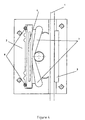
- the traditional lift brake systems basically consist of: a base or structure (2), that is fixed to the element to stop (car) and onto which the rest of the elements that make the brake are located; a brake shoe (3) that causes the braking force by friction with the guide rail (1) of the installation; a wedging element (5) which can be a roller or brake shoe that self-wedges against the guide rail after coming into contact with it as a consequence that the whole system moves together with the car, and the guide rail remains fixed; an elastic element (4) or spring intended to cause a normal force between the guide rail and the shoe brake as well as a certain deflection of the elastic element itself.
- the travel of the wedging element is limited by means of a stop (6) that is part of the structure of the brake, thereby guaranteeing, that the deflection and pressure of the elastic element are within the correct default or nominal values.
- the elastic element is based on superimposed flat plates or on single pieces with a determined shape.
- the elastic element is placed in a hole or cavity in the structure of the brake.
- the pressure that the elastic element withstands is transmitted to the structure of the brake, by means of two fixed supports in the structure of the brake, the elastic element behaving as a structure with two supports at both ends and supporting the pressure of the wedging element, which moves along the central part of the elastic element.
- the regulation of the braking capacity implies a change of the rigidity of the elastic element and is carried out in traditional systems in different ways, among them: changing the length between the supports by means of auxiliary parts (8) of interchangeable position, varying the thickness of the elastic element, substitution of the elastic element for another with similar shape, and varying any of it's dimensions as derived from a parametric formula.
- the biggest drawback of all of these systems is the need for interchangeable intermediate parts that serve as a union of the elastic element and the brake structure, or the use of different structures for each braking capacity.
- the stop that limits the travel of the wedging element is a part of the base or brake structure in know systems.
- the invention device presents a new design, based on which it allows the brake to be applied in both directions with one single elastic element and without the need for intermediate parts between it and the wedging element, be it a roller, a shoe brake, or other. All of this is accomplished with the utmost simplicity with an easy to build system.
- the elastic element is based on a long part with two opposite inclined ramps that are used to guide the wedging element in both directions of operation. This elastic element can be made up of a single part or, to simplify production, by superimposing different parts of lesser thickness.
- the elastic element is characterised for having a joint in the centre that allows it to pivot and serves as a fixing for the elastic element onto the brake structure, and for the different behaviour of its ends depending on the direction of operation: in a given direction, one of them behaves as a support while upon the other the wedging element exerts the corresponding pressure.
- the end that before acted as a support in this case, would receive the pressure from the wedging element, while the end that was receiving the pressure before, in this case would behave as a support.
- the joint can be accomplished in different ways, either by an axle, or any other type of support that permits the elastic element to pivot.
- the fixing onto the brake structure can be equally accomplished in different ways, either directly upon the brake structure or base, or by means of intermediate parts that act as bolts or a stop.
- the support can be made on both sides of the support line of the wedging system upon the elastic element.
- the braking force is produced as a consequence of the friction between the guide rail of the system and the brake shoes being part of the braking structure.
- This system permits the possibility of having a larger braking force by being able to use a second friction zone different to the one obtained from the wedging element and its corresponding brake shoe. This is accomplished as a consequence of the pivot of the elastic element around its joint and the nearing of the end of the elastic element that acts as a support to the guide rail, the end behaving as a support and braking zone simultaneously.
- the support of the elastic element can rest on the guide rail directly, or through intermediate parts that transmit its effort to the guide rail.
- the other side of the guide rail rubs against a brake shoe. This fact allows having up to two friction zones more than conventional systems used up to now.
- the elastic element described in the present report enables it without the need for additional parts and without varying the general structure of the brake support, as it can be carried out by making slots or orifices of different dimensions upon one single elastic element with fixed exterior dimensions.
- a stop for the travel limits of the wedging system may be implemented the same way as in any of the other known systems, however an innovative system can be applied in which the elastic element itself can act as a stop to limit the travel of the wedging element. This is accomplished by giving the ends of the elastic element a shape that can house the wedging element, this is especially applicable in case that the wedging system uses a roller.
- the device of the present invention is designed for allowing two-way actuation, of course, it may also be used by systems in which operation in only one direction is necessary. For these systems, and in order to reduce dimensions and to have a more compact disposition, it is possible to obtain a configuration that has these features applying the essence of the invention.
- the disposition of the elastic element for these systems relies on giving the elastic element a "V" shape, being one of its sides the ramp on which the wedging element travels, as the second ramp is not necessary.
- the joint is placed in its central part as well, and one end acts as support while the other end works as a stop for the system and is acted upon by the wedging element.
- the elastic element device can be carried out in many ways, all of which respect the essence of the invention as defined by the appended claims. Following are descriptions of four preferred implementations, three of them for two-way actuation systems and one for one-way actuation systems.
- the first preferred implementation of the elastic element (9) uses a projection (11) of the brake structure as support. This support is used as a stop for the wedging element.
- the second preferred implementation of the elastic element (12) uses as support of the elastic element bolts that are joined to the brake structure and are located on the side of the elastic element opposite the wedging element. This way the stop (14) of the wedging system is the elastic element itself.
- the third preferred implementation of the elastic element (15) is conceived to use two additional braking zones (16) as described in the report.
- the support zones (16) are against the guide rail, and the elastic element is used as a stop (17) of the wedging system.
- two brake shoes (18) are added to rub against the guide rail.
- the fourth preferred implementation of the elastic element (19) is destined to one-way actuation brakes and is characterised by the support on one end being accomplished with a bolt (20) in a similar way as the second preferred implementation, and by the other end onto which the wedging element exerts pressure being free because it is not needed as a support, as the device only acts in one direction.
- the stop (21) of the wedging system is the elastic element itself. To make the system shorter the elastic element is given the shape of a "V".
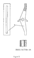
- the preferred regulation system is based on the making of orifices, slits or slots (22) of different diameters and widths to make a precise adjustment by slightly varying it's rigidity, and varying the total width (23) to accomplish a great variation of rigidity in the elastic element.
Landscapes
- Engineering & Computer Science (AREA)
- Mechanical Engineering (AREA)
- Braking Arrangements (AREA)
Claims (5)
- Sicherheitsbremsvorrichtung für Führungsschiene benutzende Transportmittel, dass in beiden Richtungen verwendet werden kann. Das System besteht aus einer Bremsstruktur (2), gekennzeichnet durch ein elastisches Element (9,12,15) aus dessen zentralen Teil zwei entgegenorientierte Arme, mit mindestens einem flexiblen Teil ausgehen. Das Element (9,12,15) ist seinem zentralen Teil auf rotierender Basis (10) mit der Bremsstruktur (2)verbunden. Wenn die Bremsstruktur in eine Richtung betrieben wird, wirkt einer der Arme auf die Klemmvorrichtung (5), die gegen die Schiene drückt. Der zweite Arm wirkt als Rückhaltsführung und bremst die Rotation des Elementhauptteiles (10).
- Sicherheitsbremsvorrichtung nach Forderung Nr.1, wo jedes der erwähnten Armen einen Bolzen (18) an dessen Ende besitzt. Wenn die Vorrichtung betrieben wird, wirkt der Bolzen des Armes gegen die Schiene und übernimmt zur selben Zeit die Bremsung zur Justierung der Bremsfähigkeit.
- Sicherheitsbremsvorrichtung nach Forderung Nr.1, wo das erwähnte flexible Element (9,12,15) Öffnungen oder Spalten zur Justierung der Bremsfähikeit besitzt.
- Sicherheitsbremsvorrichtung nach Forderung Nr.1, wo die Enden der erwähnten Armen als elastische Anschläge (14) der Klemmvorrichtung wirken.
- Sicherheitsbremsvorrichtung für Führungsschiene benutzende Transportmittel, dass in eine Richtung verwendet werden kann. Das System besteht aus einem Bremsgehäuse (2), gekennzeichnet durch ein elastisches Element (9) aus dessen zentralen Teil zwei Arme in V-Form ausgehen, mit mindestens einem Teil, der sich von diesem zentralen Teil abwendet. Das Element ist seinem zentralen Teil auf rotierender Basis (10) mit der Bremsstruktur (2) verbunden. Beim Betrieb der Bremsvorrichtung wirkt einer der Arme auf die Klemmvorrichtung (5), die gegen die Schiene drückt. Das Ende dieses Armes wirkt wie ein flexibler Anschlag (21) der Klemme. Der zweite Arm bremst die Rotation des Elementhauptteiles (10).
Applications Claiming Priority (3)
| Application Number | Priority Date | Filing Date | Title |
|---|---|---|---|
| ES9803054U | 1998-12-02 | ||
| ES009803054U ES1043007Y (es) | 1998-12-02 | 1998-12-02 | Elemento elastico para frenos de sistemas guiados. |
| PCT/ES1999/000386 WO2000032507A1 (es) | 1998-12-02 | 1999-11-29 | Elemento elastico para frenos de sistemas guiados |
Publications (2)
| Publication Number | Publication Date |
|---|---|
| EP1061032A1 EP1061032A1 (de) | 2000-12-20 |
| EP1061032B1 true EP1061032B1 (de) | 2003-07-09 |
Family
ID=8306571
Family Applications (1)
| Application Number | Title | Priority Date | Filing Date |
|---|---|---|---|
| EP99958194A Expired - Lifetime EP1061032B1 (de) | 1998-12-02 | 1999-11-29 | Elastisches element für bremse von geführten systemen |
Country Status (5)
| Country | Link |
|---|---|
| EP (1) | EP1061032B1 (de) |
| AT (1) | ATE244676T1 (de) |
| DE (1) | DE69909448D1 (de) |
| ES (1) | ES1043007Y (de) |
| WO (1) | WO2000032507A1 (de) |
Families Citing this family (5)
| Publication number | Priority date | Publication date | Assignee | Title |
|---|---|---|---|---|
| FR2882042B1 (fr) * | 2005-02-17 | 2008-10-17 | Dominique Rouzaud | Parachute bidirectionnel d'ascenseur ou similaire, et ascenseur muni d'un tel parachute |
| DE602005008205D1 (de) * | 2005-05-09 | 2008-08-28 | Dynatech Dynamics & Technology | Fangvorrichtung für eine graduelle bidirektionale Sicherheitsvorrichtung |
| EP1982945B9 (de) * | 2007-04-18 | 2011-02-02 | Wittur Holding GmbH | Brems- bzw. Fangeinrichtung mit teilweise auf Bronzebelag laufender Rolle und schräg stehender Reibfläche |
| US10421640B2 (en) * | 2017-02-17 | 2019-09-24 | Otis Elevator Company | Elevator braking device including buckling beams |
| RU2764310C1 (ru) * | 2021-02-23 | 2022-01-17 | Алексей Геннадьевич Данилов | Устройство обеспечения безопасности лифта |
Family Cites Families (5)
| Publication number | Priority date | Publication date | Assignee | Title |
|---|---|---|---|---|
| DE513405C (de) * | 1930-11-27 | Atg Ailgemeine Transportanlage | Fangvorrichtung fuer Aufzuege | |
| AT376952B (de) * | 1983-03-21 | 1985-01-25 | Otis Elevator Co | Bremsfangvorrichtung |
| EP0490090B1 (de) * | 1990-12-07 | 1995-08-09 | Inventio Ag | Bremsfangvorrichtung für Aufzugskabine und Gegengewicht |
| WO1997031852A1 (de) * | 1996-03-01 | 1997-09-04 | Cobianchi Liftteile Ag | Bremsfangvorrichtung und bremsbacke, insbesondere für aufzugskabinen |
| ES1040377Y (es) * | 1998-06-04 | 1999-08-16 | Latapia Llinas Alejandro | Freno de seguridad de ascensor paracaidas mejorado para actuacion ascendente y descendente. |
-
1998
- 1998-12-02 ES ES009803054U patent/ES1043007Y/es not_active Expired - Fee Related
-
1999
- 1999-11-29 WO PCT/ES1999/000386 patent/WO2000032507A1/es not_active Ceased
- 1999-11-29 AT AT99958194T patent/ATE244676T1/de not_active IP Right Cessation
- 1999-11-29 EP EP99958194A patent/EP1061032B1/de not_active Expired - Lifetime
- 1999-11-29 DE DE69909448T patent/DE69909448D1/de not_active Expired - Lifetime
Also Published As
| Publication number | Publication date |
|---|---|
| DE69909448D1 (de) | 2003-08-14 |
| EP1061032A1 (de) | 2000-12-20 |
| ES1043007Y (es) | 2000-05-01 |
| ATE244676T1 (de) | 2003-07-15 |
| WO2000032507A1 (es) | 2000-06-08 |
| ES1043007U (es) | 1999-11-01 |
Similar Documents
| Publication | Publication Date | Title |
|---|---|---|
| EP0440698B1 (de) | Höhenverstellbare und längenverschiebliche lenksäule | |
| CN102343913B (zh) | 悬索铁道系统及其运行方法 | |
| MX2007006356A (es) | Instalacion de elevador con equipo de frenado y metodo para frenar en una instalacion de elevador. | |
| KR20140082966A (ko) | 전기기계식 작동기능을 갖춘 제동 장치 | |
| US20090120742A1 (en) | Wear compensating devices for shoe brake devices | |
| AU713353B2 (en) | Guide equipment | |
| US7374021B2 (en) | Combined elevator guiding and safety braking device | |
| UA49942C2 (uk) | Система керування віссю транспортного засобу вздовж принаймні однієї рейки на грунті | |
| CN112088138B (zh) | 电梯的安全装置和电梯的安全系统 | |
| EP1061032A1 (de) | Elastisches element für bremse von geführten systemen | |
| JP6505740B2 (ja) | レール・ガイド式ルート・コースを有するとともにレール上をガイドされる少なくとも1台の車両を有する遊園地装置 | |
| AU723820B2 (en) | Sliding safety gear | |
| KR101957535B1 (ko) | 브레이크 블록 홀더를 가진 레일 차량용 브레이크 액츄에이터 | |
| US11167614B2 (en) | Progressive rate leaf spring for vehicle suspension system | |
| EP1549582B1 (de) | Kombinierte aufzugsführungs- und sicherheitsbremsvorrichtung | |
| US20190367331A1 (en) | Elevator system comprising at least two elevator cars that can travel along a common rail section | |
| KR20220110220A (ko) | 엘리베이터용의 안전 브레이크 | |
| KR20220057733A (ko) | 궤도차량용 퀵브레이크 장치 | |
| US5127338A (en) | Load attachment, traversing device with spring biased scissor linkage to grip cable and permit traversal of cable hangers | |
| EP1942071B1 (de) | Flotationsvorrichtung zur korrekten Festklemmung einer Lebensschutzvorrichtung | |
| US6302029B1 (en) | Vehicle for fairground rides | |
| CA2508685A1 (en) | Self-centering device for compensation ropes or chains of an elevator | |
| EP1783087B1 (de) | Notbremse für Aufzugskabinen mit doppelter Auswirkung | |
| KR920005590B1 (ko) | 궤도차량용 블록 브레이크 | |
| EP1498381B1 (de) | Positioniervorrichtung für die Führungsschienen von Aufzügen |
Legal Events
| Date | Code | Title | Description |
|---|---|---|---|
| PUAI | Public reference made under article 153(3) epc to a published international application that has entered the european phase |
Free format text: ORIGINAL CODE: 0009012 |
|
| 17P | Request for examination filed |
Effective date: 20000807 |
|
| AK | Designated contracting states |
Kind code of ref document: A1 Designated state(s): AT BE CH CY DE DK ES FI FR GB GR IE IT LI LU MC NL PT SE |
|
| 17Q | First examination report despatched |
Effective date: 20010710 |
|
| GRAG | Despatch of communication of intention to grant |
Free format text: ORIGINAL CODE: EPIDOS AGRA |
|
| GRAG | Despatch of communication of intention to grant |
Free format text: ORIGINAL CODE: EPIDOS AGRA |
|
| GRAH | Despatch of communication of intention to grant a patent |
Free format text: ORIGINAL CODE: EPIDOS IGRA |
|
| GRAH | Despatch of communication of intention to grant a patent |
Free format text: ORIGINAL CODE: EPIDOS IGRA |
|
| GRAA | (expected) grant |
Free format text: ORIGINAL CODE: 0009210 |
|
| AK | Designated contracting states |
Designated state(s): AT BE CH CY DE DK ES FI FR GB GR IE IT LI LU MC NL PT SE |
|
| PG25 | Lapsed in a contracting state [announced via postgrant information from national office to epo] |
Ref country code: NL Free format text: LAPSE BECAUSE OF FAILURE TO SUBMIT A TRANSLATION OF THE DESCRIPTION OR TO PAY THE FEE WITHIN THE PRESCRIBED TIME-LIMIT Effective date: 20030709 Ref country code: LI Free format text: LAPSE BECAUSE OF FAILURE TO SUBMIT A TRANSLATION OF THE DESCRIPTION OR TO PAY THE FEE WITHIN THE PRESCRIBED TIME-LIMIT Effective date: 20030709 Ref country code: IT Free format text: LAPSE BECAUSE OF FAILURE TO SUBMIT A TRANSLATION OF THE DESCRIPTION OR TO PAY THE FEE WITHIN THE PRESCRIBED TIME-LIMIT;WARNING: LAPSES OF ITALIAN PATENTS WITH EFFECTIVE DATE BEFORE 2007 MAY HAVE OCCURRED AT ANY TIME BEFORE 2007. THE CORRECT EFFECTIVE DATE MAY BE DIFFERENT FROM THE ONE RECORDED. Effective date: 20030709 Ref country code: FR Free format text: LAPSE BECAUSE OF FAILURE TO SUBMIT A TRANSLATION OF THE DESCRIPTION OR TO PAY THE FEE WITHIN THE PRESCRIBED TIME-LIMIT Effective date: 20030709 Ref country code: FI Free format text: LAPSE BECAUSE OF FAILURE TO SUBMIT A TRANSLATION OF THE DESCRIPTION OR TO PAY THE FEE WITHIN THE PRESCRIBED TIME-LIMIT Effective date: 20030709 Ref country code: CH Free format text: LAPSE BECAUSE OF FAILURE TO SUBMIT A TRANSLATION OF THE DESCRIPTION OR TO PAY THE FEE WITHIN THE PRESCRIBED TIME-LIMIT Effective date: 20030709 Ref country code: BE Free format text: LAPSE BECAUSE OF FAILURE TO SUBMIT A TRANSLATION OF THE DESCRIPTION OR TO PAY THE FEE WITHIN THE PRESCRIBED TIME-LIMIT Effective date: 20030709 Ref country code: AT Free format text: LAPSE BECAUSE OF FAILURE TO SUBMIT A TRANSLATION OF THE DESCRIPTION OR TO PAY THE FEE WITHIN THE PRESCRIBED TIME-LIMIT Effective date: 20030709 |
|
| REG | Reference to a national code |
Ref country code: GB Ref legal event code: FG4D |
|
| REG | Reference to a national code |
Ref country code: CH Ref legal event code: EP |
|
| REF | Corresponds to: |
Ref document number: 69909448 Country of ref document: DE Date of ref document: 20030814 Kind code of ref document: P |
|
| REG | Reference to a national code |
Ref country code: IE Ref legal event code: FG4D |
|
| PG25 | Lapsed in a contracting state [announced via postgrant information from national office to epo] |
Ref country code: SE Free format text: LAPSE BECAUSE OF FAILURE TO SUBMIT A TRANSLATION OF THE DESCRIPTION OR TO PAY THE FEE WITHIN THE PRESCRIBED TIME-LIMIT Effective date: 20031009 Ref country code: GR Free format text: LAPSE BECAUSE OF FAILURE TO SUBMIT A TRANSLATION OF THE DESCRIPTION OR TO PAY THE FEE WITHIN THE PRESCRIBED TIME-LIMIT Effective date: 20031009 Ref country code: DK Free format text: LAPSE BECAUSE OF FAILURE TO SUBMIT A TRANSLATION OF THE DESCRIPTION OR TO PAY THE FEE WITHIN THE PRESCRIBED TIME-LIMIT Effective date: 20031009 |
|
| PG25 | Lapsed in a contracting state [announced via postgrant information from national office to epo] |
Ref country code: DE Free format text: LAPSE BECAUSE OF FAILURE TO SUBMIT A TRANSLATION OF THE DESCRIPTION OR TO PAY THE FEE WITHIN THE PRESCRIBED TIME-LIMIT Effective date: 20031010 |
|
| PG25 | Lapsed in a contracting state [announced via postgrant information from national office to epo] |
Ref country code: ES Free format text: LAPSE BECAUSE OF FAILURE TO SUBMIT A TRANSLATION OF THE DESCRIPTION OR TO PAY THE FEE WITHIN THE PRESCRIBED TIME-LIMIT Effective date: 20031020 |
|
| PG25 | Lapsed in a contracting state [announced via postgrant information from national office to epo] |
Ref country code: LU Free format text: LAPSE BECAUSE OF NON-PAYMENT OF DUE FEES Effective date: 20031129 Ref country code: CY Free format text: LAPSE BECAUSE OF FAILURE TO SUBMIT A TRANSLATION OF THE DESCRIPTION OR TO PAY THE FEE WITHIN THE PRESCRIBED TIME-LIMIT Effective date: 20031129 |
|
| PG25 | Lapsed in a contracting state [announced via postgrant information from national office to epo] |
Ref country code: MC Free format text: LAPSE BECAUSE OF NON-PAYMENT OF DUE FEES Effective date: 20031130 |
|
| NLV1 | Nl: lapsed or annulled due to failure to fulfill the requirements of art. 29p and 29m of the patents act | ||
| PG25 | Lapsed in a contracting state [announced via postgrant information from national office to epo] |
Ref country code: PT Free format text: LAPSE BECAUSE OF FAILURE TO SUBMIT A TRANSLATION OF THE DESCRIPTION OR TO PAY THE FEE WITHIN THE PRESCRIBED TIME-LIMIT Effective date: 20031209 |
|
| REG | Reference to a national code |
Ref country code: CH Ref legal event code: PL |
|
| PLBE | No opposition filed within time limit |
Free format text: ORIGINAL CODE: 0009261 |
|
| STAA | Information on the status of an ep patent application or granted ep patent |
Free format text: STATUS: NO OPPOSITION FILED WITHIN TIME LIMIT |
|
| 26N | No opposition filed |
Effective date: 20040414 |
|
| PGFP | Annual fee paid to national office [announced via postgrant information from national office to epo] |
Ref country code: IE Payment date: 20040630 Year of fee payment: 5 |
|
| EN | Fr: translation not filed | ||
| PG25 | Lapsed in a contracting state [announced via postgrant information from national office to epo] |
Ref country code: IE Free format text: LAPSE BECAUSE OF NON-PAYMENT OF DUE FEES Effective date: 20041129 |
|
| PGFP | Annual fee paid to national office [announced via postgrant information from national office to epo] |
Ref country code: GB Payment date: 20041229 Year of fee payment: 6 |
|
| PG25 | Lapsed in a contracting state [announced via postgrant information from national office to epo] |
Ref country code: GB Free format text: LAPSE BECAUSE OF NON-PAYMENT OF DUE FEES Effective date: 20051129 |
|
| REG | Reference to a national code |
Ref country code: IE Ref legal event code: MM4A |
|
| GBPC | Gb: european patent ceased through non-payment of renewal fee |
Effective date: 20051129 |