EP1061037A1 - Dispositif de dosage avec piston - Google Patents
Dispositif de dosage avec piston Download PDFInfo
- Publication number
- EP1061037A1 EP1061037A1 EP00202028A EP00202028A EP1061037A1 EP 1061037 A1 EP1061037 A1 EP 1061037A1 EP 00202028 A EP00202028 A EP 00202028A EP 00202028 A EP00202028 A EP 00202028A EP 1061037 A1 EP1061037 A1 EP 1061037A1
- Authority
- EP
- European Patent Office
- Prior art keywords
- fluid
- container
- fluid outlet
- disc
- shaped element
- Prior art date
- Legal status (The legal status is an assumption and is not a legal conclusion. Google has not performed a legal analysis and makes no representation as to the accuracy of the status listed.)
- Withdrawn
Links
Images


Classifications
-
- B—PERFORMING OPERATIONS; TRANSPORTING
- B67—OPENING, CLOSING OR CLEANING BOTTLES, JARS OR SIMILAR CONTAINERS; LIQUID HANDLING
- B67D—DISPENSING, DELIVERING OR TRANSFERRING LIQUIDS, NOT OTHERWISE PROVIDED FOR
- B67D7/00—Apparatus or devices for transferring liquids from bulk storage containers or reservoirs into vehicles or into portable containers, e.g. for retail sale purposes
- B67D7/02—Apparatus or devices for transferring liquids from bulk storage containers or reservoirs into vehicles or into portable containers, e.g. for retail sale purposes for transferring liquids other than fuel or lubricants
- B67D7/0205—Apparatus or devices for transferring liquids from bulk storage containers or reservoirs into vehicles or into portable containers, e.g. for retail sale purposes for transferring liquids other than fuel or lubricants by manually operable pumping apparatus
-
- A—HUMAN NECESSITIES
- A47—FURNITURE; DOMESTIC ARTICLES OR APPLIANCES; COFFEE MILLS; SPICE MILLS; SUCTION CLEANERS IN GENERAL
- A47K—SANITARY EQUIPMENT; ACCESSORIES THEREFOR, e.g. TOILET ACCESSORIES
- A47K5/00—Holders or dispensers for soap, toothpaste or the like
- A47K5/06—Dispensers for soap
- A47K5/12—Dispensers for soap for liquid or pasty soap
- A47K5/1202—Dispensers for soap for liquid or pasty soap dispensing dosed volume
- A47K5/1204—Dispensers for soap for liquid or pasty soap dispensing dosed volume by means of a rigid dispensing chamber and pistons
-
- A—HUMAN NECESSITIES
- A47—FURNITURE; DOMESTIC ARTICLES OR APPLIANCES; COFFEE MILLS; SPICE MILLS; SUCTION CLEANERS IN GENERAL
- A47K—SANITARY EQUIPMENT; ACCESSORIES THEREFOR, e.g. TOILET ACCESSORIES
- A47K5/00—Holders or dispensers for soap, toothpaste or the like
- A47K5/06—Dispensers for soap
- A47K5/12—Dispensers for soap for liquid or pasty soap
- A47K5/1202—Dispensers for soap for liquid or pasty soap dispensing dosed volume
- A47K5/1204—Dispensers for soap for liquid or pasty soap dispensing dosed volume by means of a rigid dispensing chamber and pistons
- A47K5/1207—Dispensing from the bottom of the dispenser with a vertical piston
Definitions
- the invention relates to a metering device a container containing a viscous fluid, the at least one extending along an axis has tubular section, and with a vertical disk-shaped element extending to the axis, which is slidable in the tubular section is arranged, wherein the disc-shaped element in a direction extending away from the fluid, along their entire circumference on one towards the axis directed inside of the tubular section has adjacent flange, as well as with a Fluidumauslwiekanal, wherein the fluid between the disc-shaped element and the fluid outlet channel is arranged while on one of the viscous fluid opposite side of the disc-shaped element atmospheric pressure is present.
- the invention further relates to such a fluid containing container.
- the disc is comparatively heavy trained so that the existing fluid in the container can be pushed down.
- the disc-shaped Element has a flange that runs along the entire Circumference on an inner side of the spherical section abuts. The flange extends in a direction away from the fluid.
- the disc-shaped element a flange that faces away from the fluid Extends in the direction and has a sealing flange, which extends in the direction of the fluid is with the help of the flange ensures that no air in contact with the existing fluid in the container can and will effective stripping with the help of the sealing flange reached the inside of the container. That in the container existing fluid presses the sealing flange against the Inside, so that it is no longer possible that the Fluid between the sealing flange and the inside reached.
- a further known metering device has the container rigidly connected Wall sections on, being in one of the wall sections the fluid outlet duct is located. That in the container Containing fluid can flow out through the fluid outlet channel flow or be sucked into the container.
- the container has an air supply opening, so that due to of the outflowing fluid with air can be filled.
- Such a metering device has the disadvantage that about the oxygen, bacteria and other unwanted Elements with the risk of getting into the fluid that the fluid is attacked.
- Another disadvantage is that the complete emptying of the container, especially with viscous ones Fluids, such as liquid soap, hardly or not at all is possible because the fluid on the wall sections of the Container sticks.
- the slidable disc-shaped element causes there is an air supply opening in the container according to the invention superfluous.
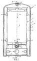
- Figures 1 to 3 each show a front view, Cross-section in side view and cross-section in top view a metering device 1 according to the invention metallic or plastic carrier 2, one from this carrier 2 supported container 3, one Carrier 2 and the container 3 surrounding attachment 4 and one Has pump mechanism 5.
- the carrier 2 has one vertically extending plate 6, the fastening eyelets 7th with which the plate 6 is attached to a wall can be.
- the carrier 2 also has one Element 8 extending perpendicular to the plate 6, in which three tubes 9, 10 extending perpendicular to the plate 6 and 11 are arranged.
- the tube 10 is on the plate 6th facing side sealed by a wall 11, comprises a vertically upwardly extending sleeve 12 and encloses an intake space 13.
- the container 3 is made using the element 8 supported.
- the container 3 has a cylindrical shape Section 14 on which is parallel to a perpendicular arranged axis 15 is arranged. This axis 15 falls together with the axis of the socket 12.
- the cylindrical section 14 is a wall element 16 sealed.
- On a wall element 16 facing away Side is in the cylindrical section 14 disc-shaped element 17 arranged which a circular plate 18, one near the center of this plate arranged cap 19 and on the circumference of the circular plate 18 has an extending sealing flange 20.
- the sealing flange 20 includes a first flange 20 'which extends in a direction away from the fluid extends.
- the sealing flange 20 also includes one Flange 20 '' which extends in the direction of the fluid.
- the flange 20 ' is above the atmospheric pressure the circular plate 18 against the wall of the cylindrical portion 14 pressed.
- the flange 20 '' is from the fluid contained in the container 3 against the Wall of the cylindrical portion 14 pressed.
- the disc-shaped element 17 is of the in the Figures 1 and 2 shown in solid lines top position in the direction indicated by arrow P1 Direction in the dashed lines and reference numerals 17 'shown, the lowest position is displaceable.
- the Container 3 has a near the wall element 16 Fluidumauslwalkanal 21 in which a closure device 22 is arranged.
- This closure device 22 has a tubular Element 23, which has an opening 24 with comparatively small diameter, a conically shaped opening 25 and an opening 26 with a comparatively large diameter contains.
- the opening 24 with the comparatively small The diameter extends into that of the container 3 formed space 27.
- the opening 26 is connected to the Socket 12 and via this socket 12 with the intake chamber 13.
- a ball 28 is arranged in the conical opening 25, by means of a spring 29 in the direction of the opening 24 is printed and closes it. The ball 28 is opposed the spring force formed by the spring 29 into that of the Arrow P2 indicated direction can be moved.
- the closure device 22 also has an in Sharp tip extending towards the container 3 30, with the help of which originally the Fluid outlet channel sealing, pierceable element 31 has been opened.
- the dossier 1 also has one Pump mechanism 5, which has an operating button 32 and extending on both sides of this control button 32 Contains pins 33.
- the pins 33 protrude into the tubes 9, 11. Press the spring 34 arranged around these pins 33 cap 32 in an opposite direction of arrow P3 Direction.
- the pump mechanism 5 also has one Fluidumauslass 35 on one end 36 in the Intake space 13 opens and with one end 36 opposite end 37 above a fluid containment position flows.
- the fluid outlet 35 is against the spring force of the Spring 34 in the direction shown by arrow P3 slidable.
- the Fluid outlet 35 is an annular one near end 36 Opening 39 on.
- the annular opening 39 is limited of two perpendicular to a centerline 40 itself extending flanges 41, 42.
- an O-ring 43 is arranged, the is slidably formed between one on the flange 41 adjacent position and one on the flange 42 adjacent position and vice versa.
- the O-ring 43 closes only partially off the annular opening 39.
- the device 1 also has one, for example made of plastic, transparent attachment 4, the the container 3 comprises and with the carrier 2 by means of a Lock 38 is releasably connectable.
- the suction space 13 is enlarged, so that a suction force is exerted on the ball 28, the then against the spring force formed by the spring 29 moved in the direction shown by arrow P2 becomes.
- the connection between the opening 24 and the opening 26 opened so that fluid from the space 27 to Intake chamber 13 can flow.
- the disc-shaped element 17 Due to the discharge of fluid from the container 3 the space required by the fluid is reduced. Doing so the disc-shaped element 17 due in particular of the negative pressure formed in the room and also due to the gravity in the arrow P1 move shown direction, which at the Inside of the cylindrical element 14 existing Fluid pressed in the direction of the fluid outlet channel 21 becomes. The disc-shaped element 17 essentially becomes as a result of the suction effect of the suction chamber 13 in the be shifted from the direction shown by arrow P1. The flange 20 '' is firmly on the inside of the cylindrical element 14 so that the flange 20 '' fluid applied to the inside from the inside away.
- the container 3 at least partially formed from transparent plastic so that on easily observed the amount of fluid in the container 3 can be.
- the disk-shaped element 17 it is also possible to have the disk-shaped element 17 to form from a material, which material through the Material of the cylindrical element 14 clearly through is visible.
- the container can also have a square cross section exhibit.
Landscapes
- Health & Medical Sciences (AREA)
- Public Health (AREA)
- Engineering & Computer Science (AREA)
- Mechanical Engineering (AREA)
- Containers And Packaging Bodies Having A Special Means To Remove Contents (AREA)
Applications Claiming Priority (2)
| Application Number | Priority Date | Filing Date | Title |
|---|---|---|---|
| NL1012332 | 1999-06-15 | ||
| NL1012332A NL1012332C2 (nl) | 1999-06-15 | 1999-06-15 | Doseerinrichting voorzien van een flu´dum omvattende houder alsmede een dergelijke houder. |
Publications (1)
| Publication Number | Publication Date |
|---|---|
| EP1061037A1 true EP1061037A1 (fr) | 2000-12-20 |
Family
ID=19769383
Family Applications (1)
| Application Number | Title | Priority Date | Filing Date |
|---|---|---|---|
| EP00202028A Withdrawn EP1061037A1 (fr) | 1999-06-15 | 2000-06-08 | Dispositif de dosage avec piston |
Country Status (2)
| Country | Link |
|---|---|
| EP (1) | EP1061037A1 (fr) |
| NL (1) | NL1012332C2 (fr) |
Cited By (2)
| Publication number | Priority date | Publication date | Assignee | Title |
|---|---|---|---|---|
| EP1857405A1 (fr) * | 2006-05-16 | 2007-11-21 | Malmi-Steel Oy | Dispositif pour le dosage d'un produit alimentaire visqueux |
| WO2013025740A1 (fr) * | 2011-08-15 | 2013-02-21 | Gojo Industries, Inc. | Distributeur doté d'une barre poussoir multidirectionnelle |
Citations (5)
| Publication number | Priority date | Publication date | Assignee | Title |
|---|---|---|---|---|
| US4819836A (en) * | 1987-06-10 | 1989-04-11 | Mega Plast Product- U. Verpackungsentwicklung Marketing Gesellschaft Mit Beschrankter Haftung & Co. | Dispenser for dispensing paste compositions |
| EP0459943A1 (fr) | 1990-05-23 | 1991-12-04 | Steiner Company International S.A. | Distributeur de produits visqueux, tel que du savon liquide ou pâteux |
| US5083416A (en) * | 1989-07-19 | 1992-01-28 | Cebal | Method and apparatus for introducing a sliding lid or seal into a tubular cylindrical body |
| EP0567369A1 (fr) * | 1992-04-22 | 1993-10-27 | S O F A B | Dispensateur de produits fluides |
| EP0903302A2 (fr) * | 1997-09-22 | 1999-03-24 | Riso Kagaku Corporation | Conteneur avec un système de réduction de volume |
Family Cites Families (2)
| Publication number | Priority date | Publication date | Assignee | Title |
|---|---|---|---|---|
| CH444698A (de) * | 1966-07-07 | 1967-09-30 | Giovanola Freres Sa | Anlage zum Ausschenken von Flüssigkeiten, insbesondere Getränken, unter Luftabschluss |
| DE19629644C2 (de) * | 1996-07-23 | 1998-08-06 | Luckhardt Ohg | Fördereinrichtung für eine pastöse Masse |
-
1999
- 1999-06-15 NL NL1012332A patent/NL1012332C2/nl not_active IP Right Cessation
-
2000
- 2000-06-08 EP EP00202028A patent/EP1061037A1/fr not_active Withdrawn
Patent Citations (5)
| Publication number | Priority date | Publication date | Assignee | Title |
|---|---|---|---|---|
| US4819836A (en) * | 1987-06-10 | 1989-04-11 | Mega Plast Product- U. Verpackungsentwicklung Marketing Gesellschaft Mit Beschrankter Haftung & Co. | Dispenser for dispensing paste compositions |
| US5083416A (en) * | 1989-07-19 | 1992-01-28 | Cebal | Method and apparatus for introducing a sliding lid or seal into a tubular cylindrical body |
| EP0459943A1 (fr) | 1990-05-23 | 1991-12-04 | Steiner Company International S.A. | Distributeur de produits visqueux, tel que du savon liquide ou pâteux |
| EP0567369A1 (fr) * | 1992-04-22 | 1993-10-27 | S O F A B | Dispensateur de produits fluides |
| EP0903302A2 (fr) * | 1997-09-22 | 1999-03-24 | Riso Kagaku Corporation | Conteneur avec un système de réduction de volume |
Cited By (2)
| Publication number | Priority date | Publication date | Assignee | Title |
|---|---|---|---|---|
| EP1857405A1 (fr) * | 2006-05-16 | 2007-11-21 | Malmi-Steel Oy | Dispositif pour le dosage d'un produit alimentaire visqueux |
| WO2013025740A1 (fr) * | 2011-08-15 | 2013-02-21 | Gojo Industries, Inc. | Distributeur doté d'une barre poussoir multidirectionnelle |
Also Published As
| Publication number | Publication date |
|---|---|
| NL1012332C2 (nl) | 2000-12-18 |
Similar Documents
| Publication | Publication Date | Title |
|---|---|---|
| DE69904833T2 (de) | Versschlussventil für behälter | |
| DE2614787C3 (de) | Vorrichtung zum Entnehmen von Fliissigkeitsproben | |
| DE3926855A1 (de) | Ausstoss-fluidverteiler mit kapselventil | |
| DE2306085A1 (de) | Nachfuellbare spruehvorrichtung | |
| DE69027699T2 (de) | Vorrichtung zur Trennung von Gas aus Flüssigkeiten und zur Entladung des ausgeschiedenen Gases | |
| DE2052859A1 (de) | Aerosolventil | |
| DE3420324A1 (de) | Abgabevorrichtung fuer mehrere stroemungsfaehige materialkomponenten | |
| DE29909542U1 (de) | Füllventil für die Befüllung von insbesondere Flachbeutelverpackungen | |
| EP1061037A1 (fr) | Dispositif de dosage avec piston | |
| DE102007013723A1 (de) | Handbetätigter Spender für pastöse bis fluide Massen und Andockbehältnis hierfür | |
| DE7631034U1 (de) | Vorrichtung zur Abgabe mindestens zweier fliessfaehiger Stoffe in vermischter Form aus einem Behaelter mittels Treibgas | |
| EP3708260A1 (fr) | Ensemble distributeur doté d'un dispositif de sortie et d'au moins un récipient contenant un milieu pouvant être pompé | |
| DE2851886B1 (de) | Vorrichtung zur dosierten Abgabe von Fluessigkeiten | |
| EP0195389B1 (fr) | Déconnecteur de tuyaux | |
| EP3541720B1 (fr) | Élément de fermeture pouvant être inséré dans une ouverture de récipient, et récipient | |
| DE68923620T2 (de) | Anordnung zum selektiven spenden und mischen von mehreren getränken. | |
| AT318948B (de) | Vorrichtung zum Aufbringen von Immersionsflüssigkeit | |
| EP0290048A2 (fr) | Pompe doseuse pour liquides épais | |
| DE3214499C2 (fr) | ||
| DE1924379A1 (de) | Selbsttaetige Abgabevorrichtung | |
| DE1937754C3 (de) | Transportable Toilette | |
| DE2029488C (de) | Abgabeventileinheit, insbesondere zum Abgeben und Mischen von mindestens zwei gesondert zugefuhrten Getrankebe standteilen | |
| DE3904173A1 (de) | Anordnung zur probenentnahme aus einem durch eine foerderleitung stroemenden produktmedium | |
| DE2158189A1 (de) | Ventil für eine unter Treibmitteldruck stehende Aerosol-Abgabevorrichtung | |
| DE4422459A1 (de) | Ausdrückvorrichtung für Doppelkartusche |
Legal Events
| Date | Code | Title | Description |
|---|---|---|---|
| PUAI | Public reference made under article 153(3) epc to a published international application that has entered the european phase |
Free format text: ORIGINAL CODE: 0009012 |
|
| AK | Designated contracting states |
Kind code of ref document: A1 Designated state(s): AT BE CH CY DE DK ES FI FR GB GR IE IT LI LU MC NL PT SE |
|
| AX | Request for extension of the european patent |
Free format text: AL;LT;LV;MK;RO;SI |
|
| 17P | Request for examination filed |
Effective date: 20010605 |
|
| AKX | Designation fees paid |
Free format text: AT BE CH CY DE DK ES FI FR GB GR IE IT LI LU MC NL PT SE |
|
| 17Q | First examination report despatched |
Effective date: 20021219 |
|
| STAA | Information on the status of an ep patent application or granted ep patent |
Free format text: STATUS: THE APPLICATION IS DEEMED TO BE WITHDRAWN |
|
| 18D | Application deemed to be withdrawn |
Effective date: 20030701 |