EP1061253A2 - Tellerventil zur Dosierung von Flüssigkeiten - Google Patents
Tellerventil zur Dosierung von Flüssigkeiten Download PDFInfo
- Publication number
- EP1061253A2 EP1061253A2 EP00112709A EP00112709A EP1061253A2 EP 1061253 A2 EP1061253 A2 EP 1061253A2 EP 00112709 A EP00112709 A EP 00112709A EP 00112709 A EP00112709 A EP 00112709A EP 1061253 A2 EP1061253 A2 EP 1061253A2
- Authority
- EP
- European Patent Office
- Prior art keywords
- valve
- gap
- sealing
- poppet valve
- poppet
- Prior art date
- Legal status (The legal status is an assumption and is not a legal conclusion. Google has not performed a legal analysis and makes no representation as to the accuracy of the status listed.)
- Granted
Links
- 239000007788 liquid Substances 0.000 title claims description 17
- 238000007789 sealing Methods 0.000 claims abstract description 26
- 230000003247 decreasing effect Effects 0.000 claims 1
- 230000000694 effects Effects 0.000 description 2
- 239000000446 fuel Substances 0.000 description 2
- 238000002347 injection Methods 0.000 description 2
- 239000007924 injection Substances 0.000 description 2
- 230000001934 delay Effects 0.000 description 1
- 230000003111 delayed effect Effects 0.000 description 1
- 238000005516 engineering process Methods 0.000 description 1
- 230000008020 evaporation Effects 0.000 description 1
- 238000001704 evaporation Methods 0.000 description 1
- 238000000034 method Methods 0.000 description 1
- 230000004048 modification Effects 0.000 description 1
- 238000012986 modification Methods 0.000 description 1
- 210000002023 somite Anatomy 0.000 description 1
- 229910001220 stainless steel Inorganic materials 0.000 description 1
- 239000010935 stainless steel Substances 0.000 description 1
Images
Classifications
-
- F—MECHANICAL ENGINEERING; LIGHTING; HEATING; WEAPONS; BLASTING
- F16—ENGINEERING ELEMENTS AND UNITS; GENERAL MEASURES FOR PRODUCING AND MAINTAINING EFFECTIVE FUNCTIONING OF MACHINES OR INSTALLATIONS; THERMAL INSULATION IN GENERAL
- F16K—VALVES; TAPS; COCKS; ACTUATING-FLOATS; DEVICES FOR VENTING OR AERATING
- F16K1/00—Lift valves or globe valves, i.e. cut-off apparatus with closure members having at least a component of their opening and closing motion perpendicular to the closing faces
- F16K1/32—Details
- F16K1/34—Cutting-off parts, e.g. valve members, seats
- F16K1/36—Valve members
- F16K1/38—Valve members of conical shape
-
- F—MECHANICAL ENGINEERING; LIGHTING; HEATING; WEAPONS; BLASTING
- F02—COMBUSTION ENGINES; HOT-GAS OR COMBUSTION-PRODUCT ENGINE PLANTS
- F02M—SUPPLYING COMBUSTION ENGINES IN GENERAL WITH COMBUSTIBLE MIXTURES OR CONSTITUENTS THEREOF
- F02M61/00—Fuel-injectors not provided for in groups F02M39/00 - F02M57/00 or F02M67/00
- F02M61/04—Fuel-injectors not provided for in groups F02M39/00 - F02M57/00 or F02M67/00 having valves, e.g. having a plurality of valves in series
- F02M61/08—Fuel-injectors not provided for in groups F02M39/00 - F02M57/00 or F02M67/00 having valves, e.g. having a plurality of valves in series the valves opening in direction of fuel flow
Definitions
- the invention relates to a poppet valve, which by corresponding Surfaces on a valve seat of the valve housing and sealed on the plate which is connected to a valve needle becomes.
- a stroke of the valve needle opens the valve and releases a sealing gap, which is usually radially symmetrical, can be designed in particular in the shape of a truncated cone.
- the geometry of the flow in the seal gap and after Leaving the valve determines the further appearance the liquid.
- FIGS axial section shown in the prior art.
- This Valve is used to generate a liquid cone jet.
- the liquid initially flows axially in the annular gap 5 between a valve needle 2 and the valve body 1 of top down towards valve plate 3 and will towards an incorporated in the valve body 1 Valve seat 4 deflected. With the valve open, it leaves the liquid the valve gap, which is also called Sealing gap is called, which is between the valve plate 3 and valve seat 4 is in the form of a cone beam.
- This cone jet has a through valve plate 3 and valve seat 4 stamped cone angle ⁇ .
- the cone jet valve therefore represents a diffuser in the open state.
- Such a large increase in the flow cross section over such a short distance leads to a strongly delayed flow and to cavitation.
- cavitation has already been observed experimentally in injection valves with a sealing surface as described above.
- the increase in volume due to the liquid itself, the compressibility of which, for example in the case of fuel, is ⁇ 10 -9 m 2 / N, during the expansion from approx. 200 bar to 1 bar, this corresponds to 2%, this geometric widening of the cross-section through which it flows does not compensate. In connection with this strong decrease in pressure, evaporation and cavitation occur.
- the invention has for its object flow delays, that involve cavitation in a poppet valve to prevent.
- the invention is based on the knowledge that the geometry of the poppet valve must be adjusted so that the flow cross-section in the seal gap is independent of the radius. This happens because, in contrast to the prior art the surface of the valve seat 4 on the valve body is the corresponding one Sealing surface on valve plate 3 is not as before are aligned in parallel.
- the cone angle ⁇ of the valve disc is designed to be larger than the cone angle ⁇ of the valve seat 4.
- the Liquid to be dosed flows from the inside out.
- the poppet valve is advantageously a Stainless steel valve designed.
- A ⁇ ⁇ HA ⁇ sin ( ⁇ / 2) ⁇ (2R-0.5HA ⁇ sin ( ⁇ )) ⁇ ⁇ ⁇ HA ⁇ sin ( ⁇ / 2) ⁇ (2R)
- tan ( ⁇ / 2) (DA-DI) / (2Y0)
- ⁇ Y0 (DA-DI) / (2tan ( ⁇ / 2))
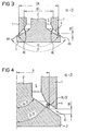
- Figures 3 and 4 show sectional drawings through a poppet valve represents, which is designed according to the prior art. It can be seen that the valve seat 4 is flat and with the opposite surface of the valve plate 3 corresponds. The surface on the valve plate has the cone angle ⁇ on. The surface of the valve seat 4 has the cone angle ⁇ , both angles being the same.
- the Sealing gap 6, i.e. the gap that occurs when the valve needle 2 transmits a stroke and the valve opens through two parallel conical surfaces.
- the radius R which is related to a cross-sectional area A is to be considered; the cross-sectional areas AE at the entry of the liquid into the sealing gap 6 and AA at the outlet of the liquid from the sealing gap 6.
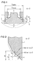
- FIGS. 1 and 2 An exemplary embodiment of the invention is shown in FIGS. 1 and 2.
- Figure 2 it can be seen that the corresponding surfaces on the valve body 1 and on the valve plate 3 are no longer parallel to represent the sealing effect.
- the angle ⁇ is larger than the angle ⁇ .
- the cross-sectional area A at the inlet of the liquid flowing from the inside to the outside when the valve is open and the sealing gap 6 is present is equal to or larger than the cross-sectional area A at the end of the sealing gap 6 when viewed in the direction of flow. Accordingly, the inner height HI is greater than the outer height HA of the sealing gap 6.
- FIG. 2 shows a possible change in the geometry at the valve seat for realizing the invention.
- This version includes the valve seat which lies flat against the valve plate 3.
- the hatched area or shape of the valve body 1 is adapted according to the invention.
- the valve is sealed by the outer tip of the valve body 1 in connection with the valve disk 3.
Landscapes
- Engineering & Computer Science (AREA)
- General Engineering & Computer Science (AREA)
- Mechanical Engineering (AREA)
- Chemical & Material Sciences (AREA)
- Combustion & Propulsion (AREA)
- Lift Valve (AREA)
- Details Of Valves (AREA)
- Fuel-Injection Apparatus (AREA)
- Sliding Valves (AREA)
Abstract
Description
Mit in Kraftstoffeinspritzventilen typischen Dimensionierungen gilt:
- Figur 1
- zeigt ein Tellerventil entsprechend der Erfindung,
- Figur 2
- zeigt einen Ausschnitt aus Figur 1, der den Ventilkörper 1 mit dem Ventilsitz 4 vergrößert darstellt,
- Figur 3 und Figur 4
- zeigen ein Tellerventil entsprechend dem Stand der Technik.
Claims (3)
- Tellerventil zur Dosierung von Flüssigkeiten bestehend aus:einem Ventilkörper (1) mit einem Ventilsitz (4),einem mit einer Ventilnadel (2) verbundenem Ventilteller (3) der mit dem Ventilsitz korrespondiert,wobei der Ventilteller (3) im geschlossenen Zustand am Ventilsitz (4) anliegt und im geöffneten Zustand ein Dichtungsspalt entsteht, der in Strömungsrichtung einen konstanten oder abnehmenden Strömungsquerschnitt aufweist.
- Tellerventil nach Anspruch 1, wobei die Strömungsrichtung der Flüssikgeit von innen nach außen gerichtet ist.
- Tellerventil nach einem der vorhergehenden Ansprüche, wobei das Tellerventil als Kegelstrahlventil ausgebildet ist.
Applications Claiming Priority (2)
| Application Number | Priority Date | Filing Date | Title |
|---|---|---|---|
| US09/336,332 US6173912B1 (en) | 1999-06-18 | 1999-06-18 | Plate valve for the dosing of liquids |
| US336332 | 1999-06-18 |
Publications (3)
| Publication Number | Publication Date |
|---|---|
| EP1061253A2 true EP1061253A2 (de) | 2000-12-20 |
| EP1061253A3 EP1061253A3 (de) | 2003-06-04 |
| EP1061253B1 EP1061253B1 (de) | 2004-08-18 |
Family
ID=23315609
Family Applications (1)
| Application Number | Title | Priority Date | Filing Date |
|---|---|---|---|
| EP00112709A Expired - Lifetime EP1061253B1 (de) | 1999-06-18 | 2000-06-15 | Tellerventil zur Dosierung von Flüssigkeiten |
Country Status (3)
| Country | Link |
|---|---|
| US (1) | US6173912B1 (de) |
| EP (1) | EP1061253B1 (de) |
| DE (1) | DE50007438D1 (de) |
Cited By (8)
| Publication number | Priority date | Publication date | Assignee | Title |
|---|---|---|---|---|
| US5877838A (en) * | 1997-04-28 | 1999-03-02 | Contour Optik Inc. | Eyeglass appliance having clamping members |
| US5883688A (en) * | 1997-04-28 | 1999-03-16 | Contour Optik, Inc. | Eyeglass frames with arms and flaps |
| US5882101A (en) * | 1997-04-28 | 1999-03-16 | Contour Optik Inc. | Auxiliary frames with ears and lateral projections |
| US5883689A (en) * | 1997-04-28 | 1999-03-16 | Contour Optik Inc. | Auxiliary frames with clamping members including resilient mechanisms |
| US6012811A (en) * | 1996-12-13 | 2000-01-11 | Contour Optik, Inc. | Eyeglass frames with magnets at bridges for attachment |
| US6364478B1 (en) | 1999-10-13 | 2002-04-02 | Arun Jaswant Jagasia | Eyeglass device having primary and auxiliary frames with lenses and method of forming the same |
| WO2009097177A1 (en) * | 2008-02-01 | 2009-08-06 | Exxonmobil Chemical Patents Inc. | High-pressure valve |
| WO2017046099A1 (de) * | 2015-09-18 | 2017-03-23 | Franke Kaffeemaschinen Ag | BRÜHVORRICHTUNG ZUM ZUBEREITEN EINES HEIßGETRÄNKS |
Families Citing this family (9)
| Publication number | Priority date | Publication date | Assignee | Title |
|---|---|---|---|---|
| DE10359302A1 (de) * | 2003-12-17 | 2005-07-21 | Robert Bosch Gmbh | Ventilkörper mit Mehrfachkegelgeometrie am Ventilstitz |
| DE102004053351B4 (de) * | 2004-11-04 | 2007-06-14 | Siemens Ag | Ventil zum Einspriten von Brennstoff |
| DE102006057425A1 (de) * | 2006-05-23 | 2007-11-29 | Robert Bosch Gmbh | Vorrichtung zur Regeneration, zur Temperaturbeaufschlagung und/oder zum Thermomanagement, zugehöriges Einspritzventil und Verfahren |
| US8006715B2 (en) | 2007-09-20 | 2011-08-30 | Caterpillar Inc. | Valve with thin-film coating |
| WO2013137467A1 (ja) * | 2012-03-15 | 2013-09-19 | カヤバ工業株式会社 | ポペット弁 |
| US9903329B2 (en) | 2012-04-16 | 2018-02-27 | Cummins Intellectual Property, Inc. | Fuel injector |
| JP6280704B2 (ja) * | 2013-07-23 | 2018-02-14 | Kyb株式会社 | 制御バルブ |
| JP6254122B2 (ja) * | 2015-06-24 | 2017-12-27 | 株式会社デンソー | 燃料噴射ノズル |
| JP6909376B2 (ja) * | 2017-06-15 | 2021-07-28 | 株式会社鷺宮製作所 | 流量制御弁及び冷凍サイクルシステム |
Family Cites Families (7)
| Publication number | Priority date | Publication date | Assignee | Title |
|---|---|---|---|---|
| US2255203A (en) * | 1940-02-28 | 1941-09-09 | Wright Aeronautical Corp | Fuel injection spark plug |
| US2555803A (en) * | 1945-09-21 | 1951-06-05 | Mashinter | Spray nozzle |
| US4958771A (en) * | 1989-06-21 | 1990-09-25 | General Motors Corporation | Injection nozzle |
| US5685492A (en) * | 1990-01-26 | 1997-11-11 | Orbital Engine Company (Australia) Pty. Limited | Fuel injector nozzles |
| WO1991011609A1 (en) * | 1990-01-26 | 1991-08-08 | Orbital Engine Company Proprietary Limited | Fuel injector nozzle |
| WO1993004277A1 (fr) * | 1991-08-15 | 1993-03-04 | Yaroslavsky Zavod Toplivnoi Apparatury | Procede et injecteur d'alimentation en carburant pour moteur a combustion interne |
| JPH08226363A (ja) * | 1995-02-20 | 1996-09-03 | Zexel Corp | 燃料噴射ノズル |
-
1999
- 1999-06-18 US US09/336,332 patent/US6173912B1/en not_active Expired - Fee Related
-
2000
- 2000-06-15 DE DE50007438T patent/DE50007438D1/de not_active Expired - Fee Related
- 2000-06-15 EP EP00112709A patent/EP1061253B1/de not_active Expired - Lifetime
Cited By (13)
| Publication number | Priority date | Publication date | Assignee | Title |
|---|---|---|---|---|
| US6367926B1 (en) | 1996-12-13 | 2002-04-09 | Contour Optik, Inc. | Eye-wear with magnets |
| US6012811A (en) * | 1996-12-13 | 2000-01-11 | Contour Optik, Inc. | Eyeglass frames with magnets at bridges for attachment |
| US6092896A (en) * | 1996-12-13 | 2000-07-25 | Contour Optik, Inc. | Eye-wear with magnets |
| US5883688A (en) * | 1997-04-28 | 1999-03-16 | Contour Optik, Inc. | Eyeglass frames with arms and flaps |
| US5882101A (en) * | 1997-04-28 | 1999-03-16 | Contour Optik Inc. | Auxiliary frames with ears and lateral projections |
| US5883689A (en) * | 1997-04-28 | 1999-03-16 | Contour Optik Inc. | Auxiliary frames with clamping members including resilient mechanisms |
| US5877838A (en) * | 1997-04-28 | 1999-03-02 | Contour Optik Inc. | Eyeglass appliance having clamping members |
| US6364478B1 (en) | 1999-10-13 | 2002-04-02 | Arun Jaswant Jagasia | Eyeglass device having primary and auxiliary frames with lenses and method of forming the same |
| US6612694B2 (en) | 1999-10-13 | 2003-09-02 | Arun Jaswant Jagasia | Eyeglass device having magnetically attached primary and auxiliary frames and method of forming the device |
| WO2009097177A1 (en) * | 2008-02-01 | 2009-08-06 | Exxonmobil Chemical Patents Inc. | High-pressure valve |
| CN101925767B (zh) * | 2008-02-01 | 2014-04-09 | 埃克森美孚化学专利公司 | 高压阀 |
| WO2017046099A1 (de) * | 2015-09-18 | 2017-03-23 | Franke Kaffeemaschinen Ag | BRÜHVORRICHTUNG ZUM ZUBEREITEN EINES HEIßGETRÄNKS |
| US10925434B2 (en) | 2015-09-18 | 2021-02-23 | Franke Kaffeemaschinen Ag | Brewing apparatus for preparing a hot beverage |
Also Published As
| Publication number | Publication date |
|---|---|
| DE50007438D1 (de) | 2004-09-23 |
| US6173912B1 (en) | 2001-01-16 |
| EP1061253A3 (de) | 2003-06-04 |
| EP1061253B1 (de) | 2004-08-18 |
Similar Documents
| Publication | Publication Date | Title |
|---|---|---|
| EP1061253B1 (de) | Tellerventil zur Dosierung von Flüssigkeiten | |
| EP1364114B1 (de) | Fluiddosiervorrichtung mit drosselstelle | |
| EP3263962B1 (de) | Ventil | |
| DE3342405C2 (de) | Absperrventil | |
| DE2553383A1 (de) | Absperrorgan | |
| WO2004109419A1 (de) | Ventil | |
| EP1741843B1 (de) | Systemtrenner | |
| EP2017511A1 (de) | Piezoelektrisches Ventil | |
| DE102007034049B3 (de) | Piezoelektrisches Ventil | |
| DE102011079636A1 (de) | Pumpenelement für eine hydraulische Kolbenpumpe | |
| CH669654A5 (de) | ||
| EP1090240B1 (de) | Druckbegrenzungsventil | |
| EP2905669B1 (de) | Druckregelventil | |
| EP0575340B1 (de) | Ventil, vorzugsweise vakuumventil | |
| EP2614276B1 (de) | Ventil zum steuern von fluiden | |
| DE3023515A1 (de) | Durchflussventil | |
| EP4187133A1 (de) | Ventil | |
| EP1601869B1 (de) | Ventil mit federelement für einen kraftstoffinjektor | |
| DE2419613A1 (de) | Steuerventil fuer hydraulische anlagen | |
| DE102017205665A1 (de) | Injektor zum Einbringen eines Fluids mit verbesserter Strahlaufbereitung | |
| EP2388467B1 (de) | Kraftstoffinjektor mit hydraulischer Kopplereinheit | |
| AT507662A4 (de) | Sprühdüse | |
| DE102020208228A1 (de) | Kraftstoff-Hochdruckpumpe | |
| EP3686465A1 (de) | Schnellschaltventil | |
| EP0655116B1 (de) | Ventil, insbesondere druckbegrenzungsventil |
Legal Events
| Date | Code | Title | Description |
|---|---|---|---|
| PUAI | Public reference made under article 153(3) epc to a published international application that has entered the european phase |
Free format text: ORIGINAL CODE: 0009012 |
|
| AK | Designated contracting states |
Kind code of ref document: A2 Designated state(s): AT BE CH CY DE DK ES FI FR GB GR IE IT LI LU MC NL PT SE |
|
| AX | Request for extension of the european patent |
Free format text: AL;LT;LV;MK;RO;SI |
|
| PUAL | Search report despatched |
Free format text: ORIGINAL CODE: 0009013 |
|
| AK | Designated contracting states |
Designated state(s): AT BE CH CY DE DK ES FI FR GB GR IE IT LI LU MC NL PT SE |
|
| AX | Request for extension of the european patent |
Extension state: AL LT LV MK RO SI |
|
| RIC1 | Information provided on ipc code assigned before grant |
Ipc: 7F 02M 61/18 B Ipc: 7F 16K 1/42 B Ipc: 7F 02M 61/08 A Ipc: 7F 16K 1/38 B |
|
| 17P | Request for examination filed |
Effective date: 20030707 |
|
| 17Q | First examination report despatched |
Effective date: 20030818 |
|
| GRAP | Despatch of communication of intention to grant a patent |
Free format text: ORIGINAL CODE: EPIDOSNIGR1 |
|
| AKX | Designation fees paid |
Designated state(s): DE FR GB IT |
|
| GRAS | Grant fee paid |
Free format text: ORIGINAL CODE: EPIDOSNIGR3 |
|
| GRAA | (expected) grant |
Free format text: ORIGINAL CODE: 0009210 |
|
| AK | Designated contracting states |
Kind code of ref document: B1 Designated state(s): DE FR GB IT |
|
| REG | Reference to a national code |
Ref country code: GB Ref legal event code: FG4D Free format text: NOT ENGLISH |
|
| GBT | Gb: translation of ep patent filed (gb section 77(6)(a)/1977) |
Effective date: 20040818 |
|
| REG | Reference to a national code |
Ref country code: IE Ref legal event code: FG4D Free format text: GERMAN |
|
| REF | Corresponds to: |
Ref document number: 50007438 Country of ref document: DE Date of ref document: 20040923 Kind code of ref document: P |
|
| REG | Reference to a national code |
Ref country code: IE Ref legal event code: FD4D |
|
| ET | Fr: translation filed | ||
| PLBE | No opposition filed within time limit |
Free format text: ORIGINAL CODE: 0009261 |
|
| STAA | Information on the status of an ep patent application or granted ep patent |
Free format text: STATUS: NO OPPOSITION FILED WITHIN TIME LIMIT |
|
| 26N | No opposition filed |
Effective date: 20050519 |
|
| PGFP | Annual fee paid to national office [announced via postgrant information from national office to epo] |
Ref country code: DE Payment date: 20070822 Year of fee payment: 8 |
|
| PGFP | Annual fee paid to national office [announced via postgrant information from national office to epo] |
Ref country code: GB Payment date: 20070607 Year of fee payment: 8 |
|
| PGFP | Annual fee paid to national office [announced via postgrant information from national office to epo] |
Ref country code: IT Payment date: 20070626 Year of fee payment: 8 |
|
| PGFP | Annual fee paid to national office [announced via postgrant information from national office to epo] |
Ref country code: FR Payment date: 20070629 Year of fee payment: 8 |
|
| GBPC | Gb: european patent ceased through non-payment of renewal fee |
Effective date: 20080615 |
|
| REG | Reference to a national code |
Ref country code: FR Ref legal event code: ST Effective date: 20090228 |
|
| PG25 | Lapsed in a contracting state [announced via postgrant information from national office to epo] |
Ref country code: DE Free format text: LAPSE BECAUSE OF NON-PAYMENT OF DUE FEES Effective date: 20090101 |
|
| PG25 | Lapsed in a contracting state [announced via postgrant information from national office to epo] |
Ref country code: GB Free format text: LAPSE BECAUSE OF NON-PAYMENT OF DUE FEES Effective date: 20080615 |
|
| PG25 | Lapsed in a contracting state [announced via postgrant information from national office to epo] |
Ref country code: FR Free format text: LAPSE BECAUSE OF NON-PAYMENT OF DUE FEES Effective date: 20080630 Ref country code: IT Free format text: LAPSE BECAUSE OF NON-PAYMENT OF DUE FEES Effective date: 20080615 |