EP1061329A2 - Procédé et système de mesure automatique et sans contact des propriétés optiques des objets optiques - Google Patents
Procédé et système de mesure automatique et sans contact des propriétés optiques des objets optiques Download PDFInfo
- Publication number
- EP1061329A2 EP1061329A2 EP00112520A EP00112520A EP1061329A2 EP 1061329 A2 EP1061329 A2 EP 1061329A2 EP 00112520 A EP00112520 A EP 00112520A EP 00112520 A EP00112520 A EP 00112520A EP 1061329 A2 EP1061329 A2 EP 1061329A2
- Authority
- EP
- European Patent Office
- Prior art keywords
- optical
- imaging
- pattern
- detecting means
- reference pattern
- Prior art date
- Legal status (The legal status is an assumption and is not a legal conclusion. Google has not performed a legal analysis and makes no representation as to the accuracy of the status listed.)
- Withdrawn
Links
Images






Classifications
-
- G—PHYSICS
- G01—MEASURING; TESTING
- G01M—TESTING STATIC OR DYNAMIC BALANCE OF MACHINES OR STRUCTURES; TESTING OF STRUCTURES OR APPARATUS, NOT OTHERWISE PROVIDED FOR
- G01M11/00—Testing of optical apparatus; Testing structures by optical methods not otherwise provided for
- G01M11/02—Testing optical properties
- G01M11/0242—Testing optical properties by measuring geometrical properties or aberrations
- G01M11/0257—Testing optical properties by measuring geometrical properties or aberrations by analyzing the image formed by the object to be tested
- G01M11/0264—Testing optical properties by measuring geometrical properties or aberrations by analyzing the image formed by the object to be tested by using targets or reference patterns
-
- G—PHYSICS
- G01—MEASURING; TESTING
- G01B—MEASURING LENGTH, THICKNESS OR SIMILAR LINEAR DIMENSIONS; MEASURING ANGLES; MEASURING AREAS; MEASURING IRREGULARITIES OF SURFACES OR CONTOURS
- G01B11/00—Measuring arrangements characterised by the use of optical techniques
- G01B11/24—Measuring arrangements characterised by the use of optical techniques for measuring contours or curvatures
- G01B11/25—Measuring arrangements characterised by the use of optical techniques for measuring contours or curvatures by projecting a pattern, e.g. one or more lines, moiré fringes on the object
- G01B11/2513—Measuring arrangements characterised by the use of optical techniques for measuring contours or curvatures by projecting a pattern, e.g. one or more lines, moiré fringes on the object with several lines being projected in more than one direction, e.g. grids, patterns
Definitions
- This invention relates to automatic non-contact measurements of optical properties of optical objects, particularly, to mapping optical objects.
- the present invention particularly refers to a method and system for mapping an ophthalmic element, where optical properties of the element such as its optical power are measured simultaneously along the element's entire surface.
- US 4,810,895, US 5,825,476 and US 5,896,194 illustrate different kinds of such methods and systems.
- US 4,810,895 discloses a method and apparatus for moire ray deflection mapping, where properties of an object are determined by producing a diverging beam of direct light from a point radiation source, passing this beam through a first optical system including the object to be examined, which system retraces the light in the form of a converging beam of reflected light from the examined object back towards the point source.
- the converging beam of reflected light is intercepted before reaching the point source and is passed through a second optical system which collimates the beam of reflected light.
- the collimated beam is then directed through first and second gratings at a preselected angular orientation with respect to each other to produce moire fringe patterns providing an indication of the properties of the examined object.
- US 5,825,476 discloses an apparatus for mapping an optical object, including a light source directing a light beam towards the optical object, an array of microlenses which divide the light beam passed through the optical object into a plurality of light beams at least some of which differ from each other, and form on a diffusive screen a corresponding plurality of images of the light source, a camera for recording these images and a computer for processing the multiple images and comparing them with a reference pattern.
- US 5,896,194 discloses an apparatus which includes a first light source for generating a lens-characteristic measuring light beam, a second light source for generating a position specifying light beam, a pattern plate with lens-characteristic measuring patterns and position specifying patterns, on which the beams from the light sources are projected through an inspected optical object to receive images of the patterns on a diffusive screen. The received images are analyzed, and the lens-characteristic mapping display of the inspected lens is performed.
- a method for automatic non-contact measuring optical properties of an optical object by means of a system comprising a light source, a reference pattern, an imaging and detecting means, at least the reference pattern and the imaging and detecting means being disposed on an optical axis of the system, and an image processing means.
- the method of the present invention comprising the steps of:
- a system for automatic non-contact measuring optical properties of an optical object comprising a light source, a reference pattern, an imaging and detecting means, at least the reference pattern and the imaging and detecting means being disposed on an optical axis of the system, a support for the optical object located between said reference pattern and said imaging and detecting means for disposing thereon the optical object coaxially with said pattern and said imaging and detecting means, said light source being capable of directing to said pattern an illuminating light in such a manner as to produce a plurality of illuminating light beams outcoming from each point of the pattern at different angles, said imaging and detecting means being capable of obtaining an image of said pattern through said optical object so that each imaging beam is conjugate with only one of said illuminating beams, and of recording said image, and an image processing means for processing said image and producing a measurement output.
- the pattern and the light source illuminating it are so designed as to ensure that the light outcoming from the illuminated reference pattern is scattered, whereby said plurality of illuminating beams outcoming from each point of the pattern is provided.
- said imaging and detecting means including a detector camera with a camera lens whose entrance pupil allows only an extremely narrow light beam to pass therethrough.
- the detector camera in fact chooses from the plurality of illuminating beams only those whose angles of incidence on the inspected optical object suit the setup of the imaging and detecting means, and uses these beams for forming the image of the reference pattern.
- the light source may be in the form of a diffusive illuminator or it may be an arbitrary monochromatic light source whose light is specifically diffused prior to its impinging the reference pattern.
- the reference pattern may be formed on transparent material such as mineral glass or it may be rather formed on a plate with a coating providing a total internal reflection.
- the pattern itself may be made of, or formed on, a diffusing (scattering) material (reflecting or transmitting) such as milky glass, ground glass or paper.
- the reference pattern is preferably in the form of a number of regularly arranged pattern elements having known dimensions and shapes and known mutual disposition.
- these elements may be points, lines or circles, concentric circular and radial lines, staggered squares, regular grid and the like.
- the pattern may have highlighted origin lines. It may be designed as a black pattern on a bright background or white pattern on a dark background. It may be in the form of a plurality of openings or slits.
- the inspected optical object introduces, due to its refractive properties, deformation into dimensions, shapes and/or positions of the elements of the imaged pattern.
- spherical power leads to the magnification of the imaged pattern elements.
- Cylindrical optical power leads to their deformation with the direction of the deformation indicating to the orientation of the cylinder axis.
- Prismatic power leads to the parallel displacement of the elements of the pattern image relative to their reference position, with the direction of the displacement indicating to the orientation of the prism axis. Measurements of these deformations enable the calculation of the optical object's refractive properties at any point and, if desired, their presentation in the form of a map of the optical object along its entire inspected area.
- the map may be a spherical optical power map, a cylindrical optical power map or a prismatic optical power map, the two latter maps being each accompanied by a corresponding vector field characterizing the direction of the respective cylinder or prism axes at different areas of the inspected optical object.
- the map may be in the form of a topographic map presenting point-to-point heights of the optical object's inspected surface.
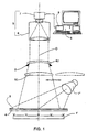
- Fig. 1 illustrates a system for automatic non-contact measuring optical properties of an optical object A1, according to one embodiment of the present invention.
- the system shown in Fig. 1 comprises a monochromatic light source 1' or 1'', a support 2 on which the optical object A1 is mounted, a precision reference pattern 3 formed on a diffusive plate 4 and having regularly arranged elements with known dimensions and shapes and known mutual disposition, an imaging and detecting means 5, and an image processing means 8.
- the reference pattern 3, the optical object A1 and the imaging and detecting means are all disposed along a common optical axis O, the object A1 being disposed at a predetermined distance from the reference pattern 3.
- the light source 1' is also located on the optical axis and is to be used when the diffusive plate 4 on which the pattern 3 is formed, is transparent. However, if the diffusive plate 4 is a reflecting plate, the light source 1'' is located aside from the optical axis O so as to illuminate the diffusive plate 4 and its pattern 3 at an angle to the optical axis.
- the imaging and detecting means 5 include a focusing optics 6, which in this case is of a telecentric or telescopic type with a high depth of focus and a detector camera 7 with a camera lens having a narrow entrance pupil (not designated) disposed at the focus of the focusing optics 6, and having a light detecting element that is not shown.
- the detector camera 7 is in the form of a high resolution camera such as CCD TV or still camera, CID or CMOS camera.
- Output of the detector 7 is connected to the image processing means 8 via a frame grabber 9.
- the image processing means 8 is in the form of a computer having a program to determine optical parameters of the inspected object A1 by processing an image of the reference pattern.
- different monitoring and analyzing systems may be used.
- the apparatus of the present invention may further include accessory compensating lens 10, positive or negative, with known optical characteristics for partly compensating of the inspected object's respective negative or positive optical power.
- the use of the compensating lens 10 enables broadening the range of lenses to be inspected by the apparatus.
- the reference pattern 3 may be built in the form of an up and down moveable unit. Inspected optical objects of high power would need positioning the reference pattern at closer distance thereto than those of low power.
- a light beam from the illuminator 1' or 1'' is directed to the reference pattern 3 through the diffusive plate 4, whereby it is provided that the light outcoming from each point of the reference pattern 3 is scattered, i.e. a plurality of illuminating beams is formed outcoming from each point of the pattern.
- the illuminating beams pass through the optical object A1 but only those of them will form an image of the reference pattern 3 that enter the focusing optics 6 as substantially parallel light beams and, consequently, pass the entrance pupil of the detector camera 7.
- Ray tracing in this case is mathematically equivalent to the ray tracing in a system with a point light source placed at the position of the entrance pupil of the camera lens 7, and a projecting screen placed at the position of the reference pattern 3.
- the optical setup in terms of lens refractive characteristic measurement is equivalent to the setup for measurements by a collimated light beam, so that mathematics developed for Hartmann method of power measurement may be applied providing results similar to the Hartmann method results.
- Fig. 8 represents an image of the reference pattern obtained through a bifocal lens with its base spherical and cylindrical power and a segment of additional power
- Fig. 9 represents an image of the reference pattern obtained through a progressive lens.
- the image recorded by the detector camera 7 is transferred to the computer 8 via the frame grabber 9, to identify the reference pattern control elements (e.g. points and/or lines, or the like) by means of a dedicated software, and to analyze the deformation introduced into the image of the reference pattern by the inspected object.
- the analysis is performed by the comparison of measured coordinates and shape of the pattern elements in the image of the reference pattern with those of an image of the reference pattern obtained by the imaging and detecting means 5 in the absence of the optical object, that is stored in the computer's memory. Based on this comparison, the deformation of the pattern image caused by the inspected optical object is determined.
- the computer 8 further uses the measured deformation of the pattern image for the calculation therefrom of the inspected object's refractive properties.
- the inspected optical object A1 is a spherical lens
- x 1 and x 2 are radial coordinates of points from which rays R1 and R2 outcome from the reference pattern 3 at angles ⁇ 1 and ⁇ 2 , X 1 and X 2 are radial coordinates of points at which the rays R1 and R2 outcome from the inspected optical object A1, B is a distance between the optical object A1 and the reference pattern 3.
- the inspected optical object A1 is a thorical lens
- its optical power spherical and cylindrical
- the coordinates X 1 , X 2 , x 1 , and x 2 are to be measured in the main cross-sections of the lens (the cross-sections taken along the axes of the cylinder).
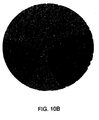
- Figs. 10A and 10B show a spherical power map of an ophthalmic progressive lens and Fig. 10B shows its cylindrical power map. It is also possible to calculate the lens power in reference points, as well as to find its optical center and, for each lens point, local axis of cylinder and prism.
- Fig. 3 illustrates a system according to another embodiment of the present invention, where measurements may be performed without the necessity of accurately pre-determining a distance between the inspected optical object and the reference pattern.
- the system of Fig. 3 comprises a support 11 for mounting an optical object A3 to be inspected, a precision reference pattern 12 formed on a transparent diffusive plate 13, a light source in the form of LED matrix 15, an imaging and detecting means including a high resolution TV camera 16 with a camera lens 17 and an additional focusing lens 18 placed on an optical axis O of the system, and the computer 8.
- the pattern 12 and the diffusive supporting plate 13 are fixed on a moveable slide 19 with a driver 20 in the form of stepper motor or servo motor controlled by the computer 8 via input/output board 21.
- a driver 20 in the form of stepper motor or servo motor controlled by the computer 8 via input/output board 21.
- the optical object A3 to be inspected is placed on the support 11 and the TV camera 16 detects, records and transfers to the computer 8 at least two images of the pattern 12 taken through the optical object A3 at two positions 'a' and 'b' of the pattern 12.
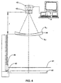
- Figs. 4 and 5 illustrate systems according to further embodiments of the present invention, for mapping in transmission of an aspherical front surface Sf of an optical object whose rear surface Sr is spherical.
- the system of Fig. 4 is designed for measuring a semi-finished progressive lens A4 with the front surface Sf having a convex aspherical shape and the rear surface Sr having a concave spherical shape.
- the system of Fig. 4 comprises an illumination means 40, a reference pattern 41, an imaging and detecting means in the form of TV camera 42 with a pinhole camera lens 43, and the computer 8.
- the optical object A4 is mounted on a support (not shown) disposed at a distance r from the pinhole lens 43, where r is a radius of curvature of the spherical rear surface Sr.
- the reference pattern 41 may be either fixed at a predetermined position for measurements similar to those in Fig.
- the system of Fig. 5 is designed for measuring refractive properties of a glass mold A5 with the front surface Sf having a concave aspherical shape and the rear surface Sr having a convex spherical shape, intended for the production of a progressive lens of Fig. 4.
- the system comprises an illumination means 50, a reference pattern 51, an imaging and detecting means including a TV camera 52 with a camera lens 53 and a focusing optics 55, and the computer 8.
- the focusing optics 55 is designed to project the entrance pupil of the camera lens 53 into a point M spaced from the pattern 51 in the direction away from the imaging and detecting means.
- the inspected optical object A5 is disposed at a distance r from the point M, where r is the radius of curvature of the convex spherical rear surface Sr.
- r is the radius of curvature of the convex spherical rear surface Sr.
- Figs. 6A and 6B illustrate systems according to further embodiments of the present invention, designed for testing optical objects with at least one reflecting surface such as metallic, ceramic and/or glass molds for production of progressive lenses, aspheric mirrors, progressive lenses, etc.
- at least one reflecting surface such as metallic, ceramic and/or glass molds for production of progressive lenses, aspheric mirrors, progressive lenses, etc.
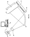
- Systems shown in Figs. 6A and 6B comprise a reference pattern 60 installed on moveable slider 61 driven by a motor 62, a diffusive light source 64 for illuminating the pattern 60, a beamsplitter 65, a field-of-view adjusting optics 66, a CCD camera 67 with a camera lens 68, a computer 70 with a frame grabber and I/O board, and a support (not shown) for an optical object A6 located on an optical axis of the system between the reference pattern 60 and the beamsplitter 65.
- the optical element A6 has an inspected surface Si which in Fig. 6A has a concave shape and in Fig. 6B has a convex shape.
- the field-of-view adjusting optics 66 has an appropriate design to form, in combination with the camera lens 68, a setup suitable for taking images in converging illuminating beams (Fig. 6A) and diverging illuminating beams (Fig. 6B).
- the field-of-view adjusting optics 66 may also be designed to work in parallel light or it even may be removed, when concave surfaces of a specific shape are inspected.
- the pattern 60 is illuminated by the diffusive light source 64 and a plurality of illuminating beams outcoming from each point of the pattern obtained thereby are directed by the beamsplitter 65 to a reflecting surface of the inspected optical element A6, wherefrom they are reflected to pass through the beamsplitter 65 and through the optics 66 towards the camera lens 68. Only those beams that pass through an entrance pupil of the camera lens 68 participate in the formation of an image of the reference pattern 60 on a detecting element of the CCD camera 67.
- the obtained image, or two images if the measurements are performed in two positions of the reference pattern 60, is/are stored in the memory of the computer 70 to be analyzed thereby in a manner similar to that discussed in previous embodiments.
- Output of the above systems working in reflection will be either in the form of a physical topographical map which will give, for each point on the inspected surface of the optical object, the real height of the surface or equivalent optical spherical, cylindrical and prismatic power maps, as shown in Figs. 10A and 10B.
- Figs. 7A and 7B show setups similar to those of Figs. 6A and 6B, designed for inspecting concave and convex surfaces in reflected light without a beamsplitting element.
Landscapes
- Physics & Mathematics (AREA)
- General Physics & Mathematics (AREA)
- Geometry (AREA)
- Chemical & Material Sciences (AREA)
- Analytical Chemistry (AREA)
- Engineering & Computer Science (AREA)
- Computer Vision & Pattern Recognition (AREA)
- Length Measuring Devices By Optical Means (AREA)
- Testing Of Optical Devices Or Fibers (AREA)
- Investigating Or Analysing Materials By Optical Means (AREA)
Applications Claiming Priority (2)
| Application Number | Priority Date | Filing Date | Title |
|---|---|---|---|
| IL13046599A IL130465A0 (en) | 1999-06-14 | 1999-06-14 | Method and apparatus for measuring power of an optical element for its mapping |
| IL13046599 | 1999-06-14 |
Publications (2)
| Publication Number | Publication Date |
|---|---|
| EP1061329A2 true EP1061329A2 (fr) | 2000-12-20 |
| EP1061329A3 EP1061329A3 (fr) | 2001-04-25 |
Family
ID=11072924
Family Applications (1)
| Application Number | Title | Priority Date | Filing Date |
|---|---|---|---|
| EP00112520A Withdrawn EP1061329A3 (fr) | 1999-06-14 | 2000-06-13 | Procédé et système de mesure automatique et sans contact des propriétés optiques des objets optiques |
Country Status (6)
| Country | Link |
|---|---|
| US (1) | US6496253B1 (fr) |
| EP (1) | EP1061329A3 (fr) |
| JP (1) | JP2001021449A (fr) |
| AU (1) | AU3942700A (fr) |
| CA (1) | CA2311050A1 (fr) |
| IL (1) | IL130465A0 (fr) |
Cited By (11)
| Publication number | Priority date | Publication date | Assignee | Title |
|---|---|---|---|---|
| WO2003025655A3 (fr) * | 2001-09-17 | 2003-10-23 | Xenogen Corp | Ensemble lentille d'imagerie ameliore concu pour des conditions de lumiere faible |
| EP1887339A1 (fr) | 2006-08-09 | 2008-02-13 | Research In Motion Limited | Procédé, appareil et système d'évaluation d'une lentille pour un appareil électronique |
| US7639353B2 (en) | 2006-08-09 | 2009-12-29 | Research In Motion Limited | Method, device and system for evaluating a lens for an electronic device |
| US8081840B2 (en) | 2004-06-09 | 2011-12-20 | Automation & Robotics | Appliance for controlling transparent or reflective elements |
| CN103439086A (zh) * | 2013-08-29 | 2013-12-11 | 中国科学院光电研究院 | 一种非接触式检测曲面棱镜的方法及装置 |
| FR3017963A1 (fr) * | 2014-02-27 | 2015-08-28 | Essilor Int | Instrument optique pour identifier et localiser des microgravures presentes sur une lentille ophtalmique |
| US9885632B2 (en) | 2014-02-27 | 2018-02-06 | Essilor International (Compagnie Generale D'optique | Optical instrument for locating at least one characteristic point of an ophthalmic lens |
| WO2018073576A3 (fr) * | 2016-10-18 | 2018-07-12 | Aston Eyetech Limited | Équipement et procédé d'examen de verre |
| GB2580946A (en) * | 2019-01-31 | 2020-08-05 | Eyoto Group Ltd | Methods and apparatus for determining prism in a lens |
| EP3726836A4 (fr) * | 2017-12-15 | 2021-08-18 | Boe Technology Group Co., Ltd. | Procédé et système de test de dispositif vestimentaire |
| GB2592431A (en) * | 2020-02-28 | 2021-09-01 | Eyoto Group Ltd | Lens examination method and apparatus |
Families Citing this family (32)
| Publication number | Priority date | Publication date | Assignee | Title |
|---|---|---|---|---|
| US6711279B1 (en) * | 2000-11-17 | 2004-03-23 | Honeywell International Inc. | Object detection |
| US7176440B2 (en) * | 2001-01-19 | 2007-02-13 | Honeywell International Inc. | Method and apparatus for detecting objects using structured light patterns |
| US6841780B2 (en) * | 2001-01-19 | 2005-01-11 | Honeywell International Inc. | Method and apparatus for detecting objects |
| FR2825466B1 (fr) * | 2001-06-05 | 2003-10-17 | Essilor Int | Dispositif de detection automatique de caracteristiques d'un verre ophtalmique et dispositif de positionnement automatique d'un pion de centrage et d'entrainement comprenant un tel dispositif de detection |
| JP4646014B2 (ja) * | 2001-08-09 | 2011-03-09 | 株式会社ニデック | レンズメータ |
| DE10146499B4 (de) * | 2001-09-21 | 2006-11-09 | Carl Zeiss Smt Ag | Verfahren zur Optimierung der Abbildungseigenschaften von mindestens zwei optischen Elementen sowie Verfahren zur Optimierung der Abbildungseigenschaften von mindestens drei optischen Elementen |
| US6771362B2 (en) * | 2001-12-27 | 2004-08-03 | Rotlex Ltd. | Method and apparatus for testing and mapping phase objects |
| US6802607B2 (en) * | 2002-10-31 | 2004-10-12 | Johnson & Johnson Vision Care, Inc. | Progressive cylinder ophthalmic lenses |
| US7532749B2 (en) * | 2003-11-18 | 2009-05-12 | Panasonic Corporation | Light processing apparatus |
| US7583821B2 (en) * | 2004-12-21 | 2009-09-01 | Avago Technologies Ecbu Ip (Singapore) Pte. Ltd. | Apparatus for classifying a material by analyzing the material's surface, and related systems and method |
| US20070071303A1 (en) * | 2005-09-29 | 2007-03-29 | Thomas Stammler | Optical system and method for improving imaging properties thereof |
| DE102006006794A1 (de) * | 2006-02-14 | 2007-08-23 | Rodenstock Gmbh | Vorrichtung zum Visualisieren und/oder Bestimmen der Verzeichnung, Verfahren und Verwendung |
| JP4296516B2 (ja) * | 2006-07-24 | 2009-07-15 | 久元電子股▲分▼有限公司 | 光学的物体距離シミュレーション装置 |
| JP4102842B1 (ja) * | 2006-12-04 | 2008-06-18 | 東京エレクトロン株式会社 | 欠陥検出装置、欠陥検出方法、情報処理装置、情報処理方法及びそのプログラム |
| EP2063260A1 (fr) * | 2007-11-19 | 2009-05-27 | Lambda-X | Système et procédé de déflectométrie de transformation de Fourier |
| CA2722154C (fr) * | 2008-05-16 | 2013-06-25 | Forensic Technology Wai Inc. | Acquisition de topographies d'objets ayant des geometries arbitraires |
| FR2932566B1 (fr) * | 2008-06-12 | 2010-11-19 | Essilor Int | Dispositif de demonstration et de test des qualites cosmetiques d'une lentille ophtalmique |
| US8823930B2 (en) * | 2012-08-07 | 2014-09-02 | Carl Zeiss Industrielle Messtechnik Gmbh | Apparatus and method for inspecting an object |
| US9097612B2 (en) * | 2012-11-30 | 2015-08-04 | Qed Technologies International, Inc. | Integrated wavefront sensor and profilometer |
| TWI456163B (zh) * | 2013-08-16 | 2014-10-11 | 財團法人金屬工業研究發展中心 | 光學影像擷取模組、對位方法及觀測方法 |
| EP3295145B1 (fr) | 2015-05-10 | 2024-08-21 | 6 Over 6 Vision Ltd. | Appareil, système et procédé de détermination d'un ou de plusieurs paramètres optiques d'un verre |
| US10670494B2 (en) | 2015-05-10 | 2020-06-02 | 6 Over 6 Vision Ltd. | Apparatus, system and method of determining one or more optical parameters of a lens |
| US10557773B2 (en) | 2016-05-18 | 2020-02-11 | Jand, Inc. | Fixtureless lensmeter system |
| US10036685B2 (en) * | 2016-05-18 | 2018-07-31 | Jand, Inc. | Fixtureless lensmeter and methods of operating same |
| RU2680615C1 (ru) * | 2018-04-10 | 2019-02-25 | АКЦИОНЕРНОЕ ОБЩЕСТВО "Научно-исследовательский институт оптико-электронного приборостроения" (АО "НИИ ОЭП") | Способ определения деформаций волнового фронта светового пучка, вызванных волнистостью поверхностей оптической системы |
| US11500197B2 (en) * | 2018-05-11 | 2022-11-15 | Arizona Board Of Regents On Behalf Of The University Of Arizona | Efficient optical system design and components |
| CN119935501A (zh) | 2019-01-10 | 2025-05-06 | 6超越6视觉有限公司 | 确定镜片的一个或多个参数的装置、系统和方法 |
| US11488239B2 (en) | 2019-08-26 | 2022-11-01 | Warby Parker Inc. | Virtual fitting systems and methods for spectacles |
| HUE065281T2 (hu) * | 2019-09-11 | 2024-05-28 | Proov Station | Gépjármû karosszériáján lévõ hibák detektálására szolgáló berendezés |
| EP4083594B1 (fr) * | 2019-12-26 | 2025-07-23 | Nidek Co., Ltd. | Dispositif de mesure de verre de lunettes et programme de mesure de verre de lunettes |
| KR20230002738A (ko) | 2020-04-15 | 2023-01-05 | 와비 파커 인코포레이티드 | 참조 프레임을 사용하는 안경용 가상 시착 시스템 |
| US12108988B2 (en) | 2020-06-17 | 2024-10-08 | Warby Parker Inc. | System and method for measuring pupillary distance and uses thereof |
Family Cites Families (15)
| Publication number | Priority date | Publication date | Assignee | Title |
|---|---|---|---|---|
| JPS5927237A (ja) | 1982-08-06 | 1984-02-13 | Nippon Kogaku Kk <Nikon> | 光学系の検査装置 |
| US4810895A (en) | 1987-01-13 | 1989-03-07 | Rotlex Optics Ltd. | Method and apparatus for optical examination of an object particularly by moire ray deflection mapping |
| JP3161787B2 (ja) | 1991-11-30 | 2001-04-25 | 株式会社ニデック | レンズ屈折力分布観察装置 |
| US5301004A (en) | 1992-03-13 | 1994-04-05 | Leica Inc. | Method and apparatus for determining the optical properties of a lens |
| US5489978A (en) | 1992-11-05 | 1996-02-06 | Canon Kabushiki Kaisha | Lens measuring apparatus |
| WO1995034800A1 (fr) | 1994-06-14 | 1995-12-21 | Visionix Ltd. | Appareil de mappage d'elements optiques |
| US5847822A (en) * | 1995-08-29 | 1998-12-08 | Asahi Kogaku Kogyo Kabushiki Kaisha | Optical element inspecting apparatus |
| US5835207A (en) * | 1995-10-02 | 1998-11-10 | Asahi Kogaku Kogyo Kabushiki Kaisha | Optical member inspecting apparatus |
| JPH09257644A (ja) | 1996-03-26 | 1997-10-03 | Topcon Corp | レンズメーター |
| JPH09288040A (ja) * | 1996-04-19 | 1997-11-04 | Topcon Corp | レンズメータ |
| US5910836A (en) | 1996-09-30 | 1999-06-08 | Kabushiki Kaisha Topcon | Lens meter |
| JP3886191B2 (ja) | 1996-12-20 | 2007-02-28 | 株式会社トプコン | レンズメーター |
| DE19712831A1 (de) | 1997-03-26 | 1998-10-01 | Delphi Automotive Systems Gmbh | Modularer Steckverbinder |
| JP3435019B2 (ja) | 1997-05-09 | 2003-08-11 | 株式会社ニデック | レンズ特性測定装置及びレンズ特性測定方法 |
| US5855074A (en) | 1997-12-07 | 1999-01-05 | Visionix Ltd. | Methods and apparatus for measuring and mapping opthalmic elements |
-
1999
- 1999-06-14 IL IL13046599A patent/IL130465A0/xx unknown
-
2000
- 2000-06-06 US US09/588,067 patent/US6496253B1/en not_active Expired - Fee Related
- 2000-06-12 CA CA002311050A patent/CA2311050A1/fr not_active Abandoned
- 2000-06-13 EP EP00112520A patent/EP1061329A3/fr not_active Withdrawn
- 2000-06-13 AU AU39427/00A patent/AU3942700A/en not_active Abandoned
- 2000-06-13 JP JP2000177485A patent/JP2001021449A/ja active Pending
Cited By (21)
| Publication number | Priority date | Publication date | Assignee | Title |
|---|---|---|---|---|
| US6754008B1 (en) | 2001-09-17 | 2004-06-22 | Xenogen Corporation | Imaging lens arrangement designed for low light conditions |
| WO2003025655A3 (fr) * | 2001-09-17 | 2003-10-23 | Xenogen Corp | Ensemble lentille d'imagerie ameliore concu pour des conditions de lumiere faible |
| US8081840B2 (en) | 2004-06-09 | 2011-12-20 | Automation & Robotics | Appliance for controlling transparent or reflective elements |
| EP1887339A1 (fr) | 2006-08-09 | 2008-02-13 | Research In Motion Limited | Procédé, appareil et système d'évaluation d'une lentille pour un appareil électronique |
| US7639353B2 (en) | 2006-08-09 | 2009-12-29 | Research In Motion Limited | Method, device and system for evaluating a lens for an electronic device |
| US7952702B2 (en) | 2006-08-09 | 2011-05-31 | Research In Motion Limited | Device and system for evaluating a lens for an electronic device |
| CN103439086B (zh) * | 2013-08-29 | 2016-03-30 | 中国科学院光电研究院 | 一种非接触式检测曲面棱镜的方法及装置 |
| CN103439086A (zh) * | 2013-08-29 | 2013-12-11 | 中国科学院光电研究院 | 一种非接触式检测曲面棱镜的方法及装置 |
| US9885632B2 (en) | 2014-02-27 | 2018-02-06 | Essilor International (Compagnie Generale D'optique | Optical instrument for locating at least one characteristic point of an ophthalmic lens |
| WO2015128589A1 (fr) * | 2014-02-27 | 2015-09-03 | Essilor International (Compagnie Générale d'Optique) | Instrument optique pour identifier et localiser des microgravures présentes sur une lentille ophtalmique |
| FR3017963A1 (fr) * | 2014-02-27 | 2015-08-28 | Essilor Int | Instrument optique pour identifier et localiser des microgravures presentes sur une lentille ophtalmique |
| US9885631B2 (en) | 2014-02-27 | 2018-02-06 | Essilor International (Compagnie Generale D'optique) | Optical instrument for identifying and locating micro-etching on an ophthalmic lens |
| WO2018073576A3 (fr) * | 2016-10-18 | 2018-07-12 | Aston Eyetech Limited | Équipement et procédé d'examen de verre |
| CN109964109A (zh) * | 2016-10-18 | 2019-07-02 | 易优托集团有限公司 | 镜片检查设备和方法 |
| US11248988B2 (en) | 2016-10-18 | 2022-02-15 | Eyoto Group Limited | Lens examination equipment and method |
| CN109964109B (zh) * | 2016-10-18 | 2022-05-27 | 易优托集团有限公司 | 镜片检查设备和方法 |
| EP3726836A4 (fr) * | 2017-12-15 | 2021-08-18 | Boe Technology Group Co., Ltd. | Procédé et système de test de dispositif vestimentaire |
| US11557106B2 (en) | 2017-12-15 | 2023-01-17 | Beijing Boe Technology Development Co., Ltd. | Method and system for testing wearable device |
| GB2580946A (en) * | 2019-01-31 | 2020-08-05 | Eyoto Group Ltd | Methods and apparatus for determining prism in a lens |
| GB2592431A (en) * | 2020-02-28 | 2021-09-01 | Eyoto Group Ltd | Lens examination method and apparatus |
| WO2021170984A1 (fr) * | 2020-02-28 | 2021-09-02 | Eyoto Group Limited | Procédé et appareil d'examen de verres |
Also Published As
| Publication number | Publication date |
|---|---|
| EP1061329A3 (fr) | 2001-04-25 |
| JP2001021449A (ja) | 2001-01-26 |
| US6496253B1 (en) | 2002-12-17 |
| IL130465A0 (en) | 2000-06-01 |
| CA2311050A1 (fr) | 2000-12-14 |
| AU3942700A (en) | 2000-12-21 |
Similar Documents
| Publication | Publication Date | Title |
|---|---|---|
| US6496253B1 (en) | Method and system for automatic non-contact measurements of optical properties of optical objects | |
| CA2648305C (fr) | Systeme et procede de mesure geometrique d'une caracteristique geometrique d'un objet | |
| US9068904B2 (en) | System and method for non-contact metrology of surfaces | |
| EP1093907A2 (fr) | Procédé et appareil pour positionner automatiquement une lentille dans un bloc de finition | |
| JP4121576B2 (ja) | 光学断面を用いたレンズパラメーター測定方法および測定装置 | |
| NO164946B (no) | Opto-elektronisk system for punktvis oppmaaling av en flates geometri. | |
| US7298468B2 (en) | Method and measuring device for contactless measurement of angles or angle changes on objects | |
| US6791696B1 (en) | Automated optical measurement apparatus and method | |
| US4984883A (en) | Translation insensitive keratometer using moire deflectometry | |
| US20030112426A1 (en) | Method and apparatus for transmission measurement of the geometrical structure of an optical component | |
| US20030053066A1 (en) | Method and apparatus for measuring the optical quality of a reflective surface | |
| US6750958B1 (en) | Automated optical measurement apparatus and method | |
| JPH10311779A (ja) | レンズ特性測定装置 | |
| US5059022A (en) | Device for measuring radius of curvature and a method thereof | |
| AU663922B2 (en) | Improvements in or relating to surface curvature measurement | |
| EP0502162B1 (fr) | Mesures de distance selon la technique moire utilisant un reseau imprime ou fixe a une surface | |
| US6924897B2 (en) | Point source module and methods of aligning and using the same | |
| EP4246087B1 (fr) | Procédé et dispositif de caractérisation d'une surface d'un objet | |
| WO1999066308A1 (fr) | Procede et dispositif automatises de mesure optique | |
| JPH11510249A (ja) | フリンジ・ディフレクトメトリ装置及びその方法 | |
| JP3218723B2 (ja) | 干渉計装置 | |
| RU59828U1 (ru) | Прибор для измерения оптических свойств и картографирования оптических объектов (варианты) | |
| JPH02242103A (ja) | 多種の用途に独立かつ選択的に操作可能な光学的検査装置 | |
| JPS6110164Y2 (fr) | ||
| Tareev | Testing collimators using a nonmisadjustable optical unit and a telescope |
Legal Events
| Date | Code | Title | Description |
|---|---|---|---|
| PUAI | Public reference made under article 153(3) epc to a published international application that has entered the european phase |
Free format text: ORIGINAL CODE: 0009012 |
|
| AK | Designated contracting states |
Kind code of ref document: A2 Designated state(s): AT BE CH CY DE DK ES FI FR GB GR IE IT LI LU MC NL PT SE |
|
| AX | Request for extension of the european patent |
Free format text: AL;LT;LV;MK;RO;SI |
|
| PUAL | Search report despatched |
Free format text: ORIGINAL CODE: 0009013 |
|
| AK | Designated contracting states |
Kind code of ref document: A3 Designated state(s): AT BE CH CY DE DK ES FI FR GB GR IE IT LI LU MC NL PT SE |
|
| AX | Request for extension of the european patent |
Free format text: AL;LT;LV;MK;RO;SI |
|
| RIC1 | Information provided on ipc code assigned before grant |
Free format text: 7G 01B 11/00 A, 7G 01M 11/02 B |
|
| 111Z | Information provided on other rights and legal means of execution |
Free format text: 20010824 AT BE CH CY DE DK ES FI FR GB GR IE IT LI LU MC NL PT SE |
|
| 17P | Request for examination filed |
Effective date: 20011025 |
|
| AKX | Designation fees paid |
Free format text: AT BE CH CY DE DK ES FI FR GB GR IE IT LI LU MC NL PT SE |
|
| STAA | Information on the status of an ep patent application or granted ep patent |
Free format text: STATUS: THE APPLICATION IS DEEMED TO BE WITHDRAWN |
|
| 18D | Application deemed to be withdrawn |
Effective date: 20060103 |