EP1061332B1 - Shearografischer Messapparat - Google Patents
Shearografischer Messapparat Download PDFInfo
- Publication number
- EP1061332B1 EP1061332B1 EP00109126A EP00109126A EP1061332B1 EP 1061332 B1 EP1061332 B1 EP 1061332B1 EP 00109126 A EP00109126 A EP 00109126A EP 00109126 A EP00109126 A EP 00109126A EP 1061332 B1 EP1061332 B1 EP 1061332B1
- Authority
- EP
- European Patent Office
- Prior art keywords
- shearogram
- animation
- interference image
- image
- test object
- Prior art date
- Legal status (The legal status is an assumption and is not a legal conclusion. Google has not performed a legal analysis and makes no representation as to the accuracy of the status listed.)
- Expired - Lifetime
Links
- 238000003384 imaging method Methods 0.000 title description 6
- 238000000034 method Methods 0.000 claims description 35
- 238000012360 testing method Methods 0.000 claims description 32
- 230000003287 optical effect Effects 0.000 claims description 18
- 239000000463 material Substances 0.000 claims description 11
- 238000010008 shearing Methods 0.000 claims description 8
- 230000001427 coherent effect Effects 0.000 claims description 7
- 230000005670 electromagnetic radiation Effects 0.000 claims description 7
- 238000012800 visualization Methods 0.000 claims description 2
- 230000000717 retained effect Effects 0.000 claims 1
- 230000007547 defect Effects 0.000 description 24
- 238000012545 processing Methods 0.000 description 8
- 230000003068 static effect Effects 0.000 description 8
- 238000004458 analytical method Methods 0.000 description 6
- 230000000694 effects Effects 0.000 description 5
- 238000010586 diagram Methods 0.000 description 4
- 230000010354 integration Effects 0.000 description 4
- 238000001514 detection method Methods 0.000 description 3
- 230000001795 light effect Effects 0.000 description 3
- 229910021532 Calcite Inorganic materials 0.000 description 2
- 239000011324 bead Substances 0.000 description 2
- 238000011161 development Methods 0.000 description 2
- 230000018109 developmental process Effects 0.000 description 2
- 238000005516 engineering process Methods 0.000 description 2
- 239000011800 void material Substances 0.000 description 2
- 238000013459 approach Methods 0.000 description 1
- 238000013473 artificial intelligence Methods 0.000 description 1
- 238000013528 artificial neural network Methods 0.000 description 1
- 239000013078 crystal Substances 0.000 description 1
- 125000004122 cyclic group Chemical group 0.000 description 1
- 230000032798 delamination Effects 0.000 description 1
- 238000005286 illumination Methods 0.000 description 1
- 230000002452 interceptive effect Effects 0.000 description 1
- 238000005305 interferometry Methods 0.000 description 1
- 239000004973 liquid crystal related substance Substances 0.000 description 1
- 238000013507 mapping Methods 0.000 description 1
- 238000005259 measurement Methods 0.000 description 1
- 238000009659 non-destructive testing Methods 0.000 description 1
- 238000003909 pattern recognition Methods 0.000 description 1
- 238000011896 sensitive detection Methods 0.000 description 1
Images

Classifications
-
- G—PHYSICS
- G01—MEASURING; TESTING
- G01B—MEASURING LENGTH, THICKNESS OR SIMILAR LINEAR DIMENSIONS; MEASURING ANGLES; MEASURING AREAS; MEASURING IRREGULARITIES OF SURFACES OR CONTOURS
- G01B11/00—Measuring arrangements characterised by the use of optical techniques
- G01B11/16—Measuring arrangements characterised by the use of optical techniques for measuring the deformation in a solid, e.g. optical strain gauge
- G01B11/161—Measuring arrangements characterised by the use of optical techniques for measuring the deformation in a solid, e.g. optical strain gauge by interferometric means
- G01B11/162—Measuring arrangements characterised by the use of optical techniques for measuring the deformation in a solid, e.g. optical strain gauge by interferometric means by speckle- or shearing interferometry
Definitions
- the present invention relates generally to the field of nondestructive testing. Specifically, the present invention relates to the technique of electronic shearography. More specifically, the present invention relates to the use of electronic shearography to detect defects in vehicle tires by animating shearograms produced while the tires undergo a varying stress continuum.
- shearography involves the interference of two laterally displaced images of the same object to form an interference image.
- Conventional shearographic methods require that a first interference image (or baseline image) be taken while the object is in an unstressed or first stressed condition, and another interference image be taken while the object is in a second stressed condition.
- Comparison of these two interference images reveals information about the strain concentrations and hence the integrity of the object in a single image called a shearogram.
- shearography has been shown to be useful to detect strain concentrations and hence defects in vehicle tires, especially retread vehicle tires.
- interference images are stored in a computer memory and are compared electronically to produce single static shearograms. Because all the data are processed electronically, the results of the analysis can be viewed in "real time”. "Real time”, as used in the prior art, refers to the ability to view the shearogram nearly instantaneously after the second interference image has been taken.
- the spatial frequency of the interference image produced in shearographic analysis was relatively high requiring the use of high resolution photographic film to record a useful interference image.
- the development disclosed in the Hung patent produces an interference image with a relatively low spatial frequency because the effective angles between the interfering rays are small. Therefore, the interference images can be recorded by a video camera, a video camera normally having much less resolving capability than a high density or high resolution photographic film.
- each point on the actual interference image is generated by the interference of light emanating from a pair of distinct points on the object. Therefore, each pixel of the video camera is illuminated by light reflected from those two points. If the overall illumination remains constant, then any variations in the pixel intensity, in the interference image, will be due only to changes in the phase relationship of the two points of light.
- an initial intensity for each pixel is recorded, as described above. If differential deformations occur in the object, such deformations will cause changes in the subsequent interference image.
- the intensity of a given pixel will change according to change in the phase relationship between the two rays of light, reflected from the two points on the object, which illuminate the pixel.
- the phase differences can be either positive changes, causing the pixel to become brighter or negative changes, causing the pixel to become darker. Whether the pixel becomes brighter or darker depends on the initial phase relationship and the direction of the change of phase. Due to the cyclic nature of phase interferences, as the deformation of the object continually increases, the intensity at a given pixel may pass through a complete cycle. That is, the intensity of the pixel might increase to a maximum (positive) difference, then return to the original intensity, and then continue to a maximum (negative) difference, and so on.
- a single shearogram is derived from two single static interference images taken at two distinct stress levels.
- the single shearogram is then viewed by an operator for analysis if multiple shearograms are taken, the analysis is done one shearogram at a time.
- the operator attendance time required to perform a thorough stress analysis, is substantial.
- a single shearogram may falsely show light features that appear to be defects (referred to as "false positives"). These "false positives" are caused by different reflective characteristics on the surface of the test object and appear as defects when a static shearogram is viewed.
- the invention accordingly has for its object to provide an improved apparatus and an improved method for performing electronic shearography on a test object.
- the present invention utilizes basic concepts of electronic shearography. More details of electronic shearography are given in U.S. Patent No. 4,887,899 .
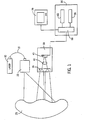
- FIG. 1 a schematic block diagram of an arrangement for practicing electronic shearography is depicted.
- Coherent electromagnetic radiation or coherent light is produced by a laser 10, the laser light being directed through a fiberoptic cable 15 (or alternatively directed by a mirror or a set of mirrors or provided directly) to a beam expander or illuminator 20.
- Beam expander 20 directs the coherent light onto a test object 25.
- the surface of test object 25 is illuminated and reflects light into a shearography camera 30.
- Shearography camera 30 includes an optical element 35, a lens 40 for focusing the light, and a detector 45.
- Optical element 35 may be a birefringent material and a polarizer, the birefringent material being a calcite material such as a Walleston prism.
- the optical element is however not limited to a birefringent material and a polarizer, other elements such as a defraction grating, a Michelson mirror, or an appropriate wave plate may be applied.
- optical element 35 may contain other optics, such as, but not limited to a quarter-wave plate.
- Detector 45 may be a traditional video camera, a digital video camera, a charge coupled device (CCD), or other photo sensitive detection equipment.
- Computer 50 includes a video capture circuit 55, a central processing unit 60, and a memory 65.
- computer 50 may include a logical extractor that is configured to extract shearographic images from memory in a predetermined manner.
- the logical extractor may be embodied in hardware or alternatively in software within computer 50.
- Video capture circuit 55 may be a dedicated video card or a frame grabber preferably capable of capturing entire video images at a rate of at least 15 frames per second. However, video capture circuit 55 may be capable of capturing video images at any suitable rate.
- Central processing unit 60 may be any of a number of conventional microprocessors or a dedicated microprocessor device.
- Detector 45 is coupled to central processing unit 60, central processing unit 60 being coupled to video capture circuit 55 and memory device 65.
- Central processing unit 60 is further coupled to a display unit 70, which may be a CRT (cathode ray tube) display, an LCD (liquid crystal display), or the like.
- coherent light emanating from beam expander 20 is reflected from test object 25.
- Optical element 35 collects the reflected light from object 25 causing an interference image to be created.
- the interference image is focused on detector 45 through lens 40.
- a first interference image is taken while test object 25 is in a first stressed condition, and a second interference image is taken with object 25 in a second stressed condition.
- the two interference images are then compared by a process of subtracting one image from the other and the shearogram is created and displayed on a monitor.
- test object 25 undergoes a sequence of or continuum of varying stress levels.
- Detector 45 continuously captures the interference image from optical element 35 and communicates the interference image to computer 50, during the stress cycle.
- Capture circuit 55 electronically captures entire interference images at a rate of at least 15 frames per second.
- Capture circuit 55 communicates the interference images to central processing unit 60.
- Central processing unit 60 compares the interference image to a baseline interference image of the object in the unstressed or near unstressed state (or alternatively any chosen stress state), by a process of subtracting one interference image from the baseline interference image, thereby forming a shearogram.
- Each shearogram image is simultaneously displayed on display unit 70 and stored in memory device 65.
- microprocessor 60 recalls the sequence of shearogram images captured by capture circuit 55 and replays them in sequence on display unit 70.
- the sequential display of these shearogram images at a rate of at least 15 frames per second, produces a shearographic animation of the shearograms produced during or after stressing of test object 25.
- Test object 25 may be a relatively large object, such as a tire 200, as depicted in FIG. 2 .
- a shearographic camera 230 that is rotatable within the inside of the bead 202 of tire 200 is depicted in FIG. 2 .
- tire 200 may be rotated and camera 230 may be stationary.
- Shearographic camera 230 includes a laser 235 producing a coherent beam of light to illuminate the inside of tire 200.
- Shearographic camera 235 is further coupled to a computer 240 having a display 245, computer 240 and display 245 being used for data acquisition and animation of the resultant shearographic images.
- shearographic imaging camera 230 When used for detection of defects in tires or retread tires, shearographic imaging camera 230 may be positioned inside the tire depicted as position A in FIG. 3 or outside the tire as depicted in FIG. 3 by position B. Having shearographic camera 230 in position A allows for detection of defects in the tread area of tire 200. Having shearographic camera 230 in position B provides for examination of the bead area and side wall area of tire 200.
- shearographic camera 230 and tire 200 may be placed into a vacuum chamber capable of subjecting tire 200 to a vacuum producing stresses on tire 200 by producing a positive pressure (relative to the pressure inside the vacuum chamber) in voids within tire 200 causing a bulge 250.
- the bulge may be caused by a defect 260, defect 260 possibly being but not limited to a delamination between two layers of the tire or a void in the molded material.
- bulge 250 appears because of positive pressure within the void space of bond 260.
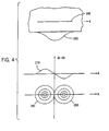
- the graph of FIG. 4 depicts the slope of bulge 250 by line 270.
- Fringe patterns 280 and 290 of a shearogram image is produced by computer 240 (by the method of differencing or by any other image resolving technique) appear as a set of roughly concentric, substantially circular fringe lines corresponding to slope 270 of bulge 250.
- Fringe patterns 280 and 290 are a contour mapping of the absolute value of slope 270 of bulge 250. Therefore, because bulge 250 is substantially symmetric, fringe patterns 280 and 290 appear to be mirror images of each other.
- shearographic camera 230 takes a series of interference images that are communicated to computer 240 while tire 200 undergoes varying vacuum or stress cycle.
- tire 200 undergoes a depressurization cycle and then a pressurization cycle to return the tire to an unstressed state.
- a tire must be sectioned into a number of sectors ranging from four to twelve, or more.
- tire 200 is sectioned into nine different sectors.
- Shearographic camera 230 therefore views an area corresponding to 40° of arc of tire 200.
- Computer 240 continues to collect data and may, in a preferred embodiment, simultaneously display data on display 245 throughout the entirety of the nine sector cycle.
- the shearograms are generated and displayed at a rate such that they appear to be animated.
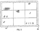
- FIG. 5 a display 300 is depicted, the display being divided into nine different sectors, each sector 310 corresponding to an approximate 40° arc of the inside of a tire. Alternatively, however, each sector 310 could correspond to any specific field of view, of a tire, for a shearographic camera, such as shearographic camera 230.
- Computer 240 as depicted in FIG. 2 , which may be connected to display 300, is capable of displaying a plurality of animations simultaneously as depicted in FIG. 5.
- FIG. 5 depicts a static screen shot of a typical display, however, display 300 actually shows animations or sequential imaging of shearogram images produced by computer 240 at a rate providing an animated effect and in a preferred embodiment at a rate of 30 frames per second.
- a display having multiple animation windows or screen sectors provides the clear advantage that an operator may observe the animations simultaneously looking for the appearance of indications of deformations due to defects. This simultaneous observation permits less attendance time by an operator, therefore providing substantial time savings without substantial loss of accuracy. Capturing and providing animation preferably at 30 frames per second (or alternatively any suitable animation rate) provides animations that are sufficiently smooth to be useful to an operator.
- animation improves accuracy in the detection of defects.
- Light effects that would appear as “false positives” in a static shearogram are not manifested as defects when animated, due to the absence of apparent motion induced by the animation.
- a fringe pattern caused by a real defect will tend to "grow” or “shrink” and the intensity of fringe lines will appear to cycle during the animation, due to the continually changing stress state on the test object.
- real defects that may be "washed out” in a static shearogram or even in an integration of multiple shearographic images become apparent with animation of the shearographic images.
- Animation of the shearographic images allows visualization of defects at a multiplicity of stress states, some of the stress states may not cause the "washed out” effect and further the apparent motion created by animation of the images manifests a real defect as opposed to the light effect. Animation of the shearograms goes through a substantial continuity of stress states, therefore defects that may not be present at two chosen stress states become apparent in the animation. These advantages in animation of the shearographic images provide better accuracy in detecting defects and provides for shorter analysis times by an operator.
- animation of shearographic images may be preferable at a rate of at least 15 frames per second, it should be noted that frame rates of less than 15 frames per second may also be used effectively, however the animation may appear discretized as compared to an animation running at least 15 frames per second. Further, it should be appreciated that frame rates of more than 30 frames per second may be advantageous in specific applications and may become simpler to implement as microprocessor and video capture technology is improved.
- Continuous integration describes the process of taking a first interference image and subtracting a second interference image to produce a first shearogram.
- a third interference image is taken and subtracted from the first shearogram to produce a second shearogram.
- a fourth interference image is then taken and subtracted from the second shearogram to produce a third shearogram. This sequence is continued throughout the testing cycle.
- the continuous integration technique and other techniques known to those of ordinary skill in the art lend themselves to the animation techniques disclosed above and can be applied thereto without departing from the scope of the present invention, as defined by the appended claims.
Landscapes
- Physics & Mathematics (AREA)
- General Physics & Mathematics (AREA)
- Investigating Materials By The Use Of Optical Means Adapted For Particular Applications (AREA)
- Length Measuring Devices By Optical Means (AREA)
- Investigating Strength Of Materials By Application Of Mechanical Stress (AREA)
- Investigating Or Analysing Materials By Optical Means (AREA)
- Holo Graphy (AREA)
Claims (26)
- Ein Apparat zur Durchführung elektronischer Shearografie an einem Testobjekt, umfassend:eine Quelle kohärenter elektromagnetischer Strahlung (10) zum Beleuchten des Testobjektes (25);ein optisches Element (35), durch das von dem Testobjekt (25) reflektierte elektromagnetische Strahlung unter Bildung eines Interferenzabbildes weitergeleitet wird;einen Detektor (45), wobei der Detektor (45) das Interferenzabbild in ein elektrisches Signal umwandelt, das für das Interferenzabbild repräsentativ ist;gekennzeichnet durcheine Animationsvorrichtung (50), die mit dem Detektor (45) gekoppelt ist, wobei die Animationsvorrichtung (50) das elektrische Signal empfängt, das für das Interferenzabbild repräsentativ ist, die Animationsvorrichtung (50) Abbildinformation, die aus den elektrischen Signalen abgeleitet wurde, die für das Interferenzabbild repräsentativ sind, mit einer vorbestimmten Framerate sichert, die Animationsvorrichtung (50) die gesicherte Interferenzabbildinformation mit einem Basislinieninterferenzabbild zur Erzeugung eines Shearogrammbildes vergleicht, und die Animationsvorrichtung (50) angepasst ist, eine Animation abzuspielen, die eine Reihe von sequenziellen Shearogrammbildern umfasst, die für sich verändernde Belastungszustände an dem Testobjekt repräsentativ sind, wobei die Animation eine scheinbare Bewegung erzeugt; undeine Anzeigevorrichtung (70), die mit der Animationsvorrichtung gekoppelt ist, die eine Sichtbarmachung der Animation der sequenziellen Shearogrammbilder bereitstellt.
- Der Apparat nach Anspruch 1, wobei die Animationsvorrichtung ferner eine Erfassungsschaltung (55) umfasst, die angepasst ist, sequenziell die Interferenzabbildinformation zu sichern.
- Der Apparat nach Anspruch 2, wobei die Animationsvorrichtung ferner eine Speichervorrichtung (65), die mit der Erfassungsschaltung (55) gekoppelt ist, zum Speichern mindestens eines aus Interferenzabbildinformation und Shearogrammabbildinformation umfasst, die der Speichervorrichtung (65) von der Erfassungsschaltung (55) kommuniziert werden.
- Der Apparat nach Anspruch 3, wobei die Animationsvorrichtung (50) angepasst ist, sequenzielle Shearogrammbilder abzuspielen, die in der Speichervorrichtung (65) gespeichert sind.
- Der Apparat nach Anspruch 4, wobei die Animationsvorrichtung (50) angepasst ist, sequenzielle Shearogrammbilder im Wesentlichen mit der gleichen Framerate wie die Sicherungs-Framerate abzuspielen.
- Der Apparat nach Anspruch 5, wobei die vorbestimmte Framerate mindestens fünfzehn (15) Frames pro Sekunde beträgt.
- Der Apparat nach Anspruch 6, wobei der Detektor (45) eine Videokamera ist.
- Der Apparat nach Anspruch 6, wobei der Detektor (45) eine digitale Videokamera ist.
- Der Apparat nach Anspruch 6, wobei der Detektor (45) eine ladungsgekoppelte Vorrichtungsanordnung ist.
- Der Apparat nach Anspruch 6, wobei die Animationsvorrichtung (50) ein Computer ist.
- Der Apparat nach Anspruch 6, wobei die Speichervorrichtung (65) Sequenzen mindestens eines aus Interferenzabbildern und Shearogrammbildern speichert, die für verschiedene Abschnitte des Testobjektes repräsentativ sind.
- Der Apparat nach Anspruch 11, wobei die Animationsvorrichtung (50) angepasst ist, im Wesentlichen gleichzeitig mehrere Shearogrammbildsequenzen abzuspielen, die für verschiedene Abschnitte des Testobjektes repräsentativ sind, und wobei die Animationsvorrichtung (50) im Wesentlichen gleichzeitig die mehreren Shearogrammbildsequenzen auf der Anzeigevorrichtung abspielt.
- Der Apparat nach Anspruch 12, wobei die Animationsvorrichtung (50) angepasst ist, neun Shearogrammbildsequenzen gleichzeitig abzuspielen.
- Der Apparat nach Anspruch 12, wobei die Animationsvorrichtung (50) angepasst ist, alle neun Shearogrammbildsequenzen im Wesentlichen gleichzeitig mit jeweils einer Framerate von mindestens fünfzehn Frames pro Sekunde abzuspielen.
- Ein Verfahren zur Analyse eines Testobjektes, wobei das Verfahren folgendes umfasst:(a) Lenken kohärenter elektromagnetischer Strahlung auf ein Testobjekt (25);(b) Bereitstellen elektromagnetischer Strahlung, die von dem Testobjekt (25) reflektiert wurde, für eine optische Shearing-Vorrichtung (35), wobei die optische Shearing-Vorrichtung (35) ein Interferenzabbild erzeugt;(c) Lenken des Interferenzabbildes, das aus der Shearing-Vorrichtung (35) hervortritt, auf einen Detektor (45);(d) Erfassen eines elektrischen Signals, das von dem Detektor (45) kommuniziert wurde, in einer Erfassungsvorrichtung (55), wobei das elektrische Signal für das Interferenzabbild repräsentativ ist;(e) Speichern von Interferenzabbildinformation in einer Speichervorrichtung (65), die von der Erfassungsvorrichtung (55) kommuniziert wurde;(f) Vergleichen von Interferenzabbildinformation, die in der Speichervorrichtung (65) gespeichert ist, mit einem gespeicherten Interferenzabbild zur Erzeugung eines Shearogrammbildes;(g) Wiederholen der Schritte (a) bis (f) bei variierenden Belastungsgraden;
gekennzeichnet durch(h) Anzeigen von Shearogrammabbildinformation mit einer Framerate, die eine Animation bereitstellt, die eine Reihe von sequenziellen Shearogrammbildern umfasst, die für sich verändernde Belastungszustände an dem Testobjekt (25) repräsentativ sind, wobei die Animation eine scheinbare Bewegung erzeugt. - Das Verfahren nach Anspruch 15, wobei die optische Shearing-Vorrichtung (35) ein doppelbrechendes Material ist.
- Das Verfahren nach Anspruch 16, wobei die optische Shearing-Vorrichtung (35) einen Polarisator einschließt.
- Das Verfahren nach Anspruch 15, wobei die optische Shearing-Vorrichtung (35) ein Michelson-Spiegel ist.
- Das Verfahren nach Anspruch 15, wobei die Framerate mindestens 15 Frames pro Sekunde beträgt.
- Das Verfahren nach Anspruch 19, das ferner den folgenden Schritt umfasst: Durchführen der Schritte (a) bis (g) mehrere Male.
- Das Verfahren nach Anspruch 20, das ferner das Anzeigen einer Vielzahl von sequenziellen Shearogrammbildern im Wesentlichen gleichzeitig auf einer Anzeigevorrichtung (70) umfasst.
- Ein Apparat nach Anspruch 1, wobei das Testobjekt ein Reifen ist, der variierenden Belastungsgraden unterzogen wird, gekennzeichnet durch:das optische Element (35) schließt ein doppelbrechendes Material ein, durch das von dem Reifen reflektierte elektromagnetische Strahlung weitergeleitet wird, und einen Polarisator, durch den aus dem doppelbrechenden Material hervortretende elektromagnetische Strahlung weitergeleitet wird, wobei das doppelbrechende Material und der Polarisator zur Bildung eines Interferenzabbildes zusammenwirken;der Detektor (45) umfasst eine Videokamera; unddie Animationsvorrichtung (50) schließt eine Videoerfassungsschaltung (55), die mit der Videokamera gekoppelt ist, und einen Computer ein, der mit der Erfassungsschaltung gekoppelt ist.
- Der Apparat nach Anspruch 22, wobei die Framerate mindestens 15 Frames pro Sekunde beträgt.
- Der Apparat nach Anspruch 23, wobei die Kamera (45) angepasst ist, einen Abschnitt des Reifens zu betrachten, der mindestens ein Neuntel der projizierten Reifenfläche beträgt.
- Der Apparat nach Anspruch 24, wobei der Computer (50) angepasst ist, neun separate Shearogrammbildsequenzen zu erfassen, wobei jede Shearogrammbildsequenz für einen im Wesentlichen verschiedenen Abschnitt des Reifens repräsentativ ist.
- Der Apparat nach Anspruch 25, wobei der Computer (50) angepasst ist, alle neun Shearogrammbildsequenzen im Wesentlichen gleichzeitig anzuzeigen, wobei jede Shearogrammbildsequenz mit einer Framerate von mindestens 15 Frames pro Sekunde angezeigt wird.
Applications Claiming Priority (2)
| Application Number | Priority Date | Filing Date | Title |
|---|---|---|---|
| US334311 | 1989-04-06 | ||
| US09/334,311 US6219143B1 (en) | 1999-06-16 | 1999-06-16 | Method and apparatus for analyzing shearogram images by animation |
Publications (3)
| Publication Number | Publication Date |
|---|---|
| EP1061332A2 EP1061332A2 (de) | 2000-12-20 |
| EP1061332A3 EP1061332A3 (de) | 2003-01-29 |
| EP1061332B1 true EP1061332B1 (de) | 2012-08-15 |
Family
ID=23306635
Family Applications (1)
| Application Number | Title | Priority Date | Filing Date |
|---|---|---|---|
| EP00109126A Expired - Lifetime EP1061332B1 (de) | 1999-06-16 | 2000-05-05 | Shearografischer Messapparat |
Country Status (5)
| Country | Link |
|---|---|
| US (2) | US6219143B1 (de) |
| EP (1) | EP1061332B1 (de) |
| JP (1) | JP2001066259A (de) |
| BR (1) | BR0002632B1 (de) |
| CA (1) | CA2310201C (de) |
Families Citing this family (34)
| Publication number | Priority date | Publication date | Assignee | Title |
|---|---|---|---|---|
| US6219143B1 (en) * | 1999-06-16 | 2001-04-17 | Bandag, Incorporated | Method and apparatus for analyzing shearogram images by animation |
| US6791695B2 (en) * | 1999-06-16 | 2004-09-14 | Bandag Licensing Corporation | Shearographic imaging machine with archive memory for animation data and air handling system |
| JP2002111942A (ja) * | 2000-09-29 | 2002-04-12 | Matsushita Electric Ind Co Ltd | 画像処理装置 |
| EP1284409A1 (de) * | 2001-08-16 | 2003-02-19 | Bernward Mähner | Verfahren und Vorrichtung zur Untersuchung der Verformung von Prüfobjekten |
| US6674531B2 (en) * | 2001-08-17 | 2004-01-06 | Maehner Bernward | Method and apparatus for testing objects |
| JP4515261B2 (ja) * | 2002-08-29 | 2010-07-28 | ノーコム システムズ インク. | シール品の漏洩を検知するシステム及びプロセス |
| DE10319099B4 (de) | 2003-04-28 | 2005-09-08 | Steinbichler Optotechnik Gmbh | Verfahren zur Interferenzmessung eines Objektes, insbesondere eines Reifens |
| US20040227954A1 (en) * | 2003-05-16 | 2004-11-18 | Tong Xie | Interferometer based navigation device |
| US7321359B2 (en) * | 2003-07-30 | 2008-01-22 | Avago Technologies Ecbu Ip (Singapore) Pte. Ltd. | Method and device for optical navigation |
| US7187437B2 (en) * | 2003-09-10 | 2007-03-06 | Shearographics, Llc | Plurality of light sources for inspection apparatus and method |
| US6934018B2 (en) * | 2003-09-10 | 2005-08-23 | Shearographics, Llc | Tire inspection apparatus and method |
| US7436504B2 (en) * | 2003-09-10 | 2008-10-14 | Shear Graphics, Llc | Non-destructive testing and imaging |
| US6963434B1 (en) * | 2004-04-30 | 2005-11-08 | Asml Holding N.V. | System and method for calculating aerial image of a spatial light modulator |
| DE102004050355A1 (de) * | 2004-10-15 | 2006-04-27 | Steinbichler Optotechnik Gmbh | Verfahren und Vorrichtung zum Prüfen der Oberfläche eines Reifens |
| US7399954B2 (en) * | 2005-08-16 | 2008-07-15 | Avago Technologies Ecbu Ip Pte Ltd | System and method for an optical navigation device configured to generate navigation information through an optically transparent layer and to have skating functionality |
| EP2047338B1 (de) | 2006-07-18 | 2018-12-05 | Celloptic, Inc. | Vorrichtung und verfahren zum extrahieren dreidimensionaler informationen eines objekts aus empfangener elektromagnetischer strahlung |
| US7903115B2 (en) * | 2007-01-07 | 2011-03-08 | Apple Inc. | Animations |
| US7978093B2 (en) * | 2007-11-09 | 2011-07-12 | Bridgestone Americas Tire Operations, Llc | Comparative tire animation |
| JP5670161B2 (ja) * | 2010-11-25 | 2015-02-18 | 東洋ゴム工業株式会社 | タイヤの検査装置 |
| US8824878B2 (en) * | 2010-11-25 | 2014-09-02 | Toyo Tire & Rubber Co., Ltd. | Illumination device and inspection device of tire |
| US8717577B1 (en) * | 2011-01-24 | 2014-05-06 | Bae Systems Information And Electronic Systems Integration Inc. | Compensating aperture for utilizing shearography from a moving platform |
| ITMI20112253A1 (it) * | 2011-12-13 | 2013-06-14 | Pirelli | Metodo per controllare la deposizione di semilavorati elementari in un processo di confezione di pneumatici per ruote di veicoli |
| US8875579B2 (en) * | 2012-03-26 | 2014-11-04 | GM Global Technology Operations LLC | Method and apparatus for non-destructive weld testing |
| JP6034961B2 (ja) * | 2012-06-01 | 2016-11-30 | ブリヂストン バンダッグ リミティッド ライアビリティ カンパニーBridgestone Bandag, LLC. | シェアログラフィック撮像マシン及び方法 |
| CN105684044B (zh) * | 2013-08-28 | 2018-06-12 | 维斯塔斯风力系统有限公司 | 分析层压物体中的形变的方法及相应系统 |
| CA2928709C (en) | 2013-10-28 | 2020-01-07 | Oakland University | Spatial phase-shift shearography system for non-destructive testing and strain measurement |
| CN114720159B (zh) * | 2014-12-05 | 2025-08-12 | 倍耐力轮胎股份公司 | 用于检查轮胎的方法和设备 |
| KR101892096B1 (ko) * | 2016-11-10 | 2018-10-04 | 금호타이어 주식회사 | 비파괴검사 이미지 분석을 통한 타이어 결함 판정 방법 |
| WO2018116031A1 (en) * | 2016-12-20 | 2018-06-28 | Pirelli Tyre S.P.A. | Method for checking the formation of beads of tyres and related station |
| US10180403B1 (en) * | 2017-06-21 | 2019-01-15 | The Boeing Company | Shearography for sub microcellular substrate nondestructive inspection |
| CN109458943B (zh) * | 2018-11-07 | 2020-11-06 | 中国电子科技集团公司第三十八研究所 | 一种dic技术随机散斑生成方法 |
| CN112858344B (zh) * | 2021-01-20 | 2022-09-20 | 昆明理工大学 | 一种无损检测装置及方法 |
| CN116929286A (zh) * | 2022-04-01 | 2023-10-24 | 北京振兴计量测试研究所 | 一种基于数字图像的高温应变传感器校准装置及校准方法 |
| WO2025188731A1 (en) | 2024-03-04 | 2025-09-12 | Compagnie Generale Des Etablissements Michelin | Improved tire shearography inspection |
Family Cites Families (18)
| Publication number | Priority date | Publication date | Assignee | Title |
|---|---|---|---|---|
| US4702594A (en) * | 1982-11-15 | 1987-10-27 | Industrial Holographics, Inc. | Double exposure interferometric analysis of structures and employing ambient pressure stressing |
| JPS61102857U (de) * | 1984-12-10 | 1986-06-30 | ||
| US4887899A (en) | 1987-12-07 | 1989-12-19 | Hung Yau Y | Apparatus and method for electronic analysis of test objects |
| US5011280A (en) | 1987-12-07 | 1991-04-30 | Hung Yau Y | Method of measuring displacement between points on a test object |
| US5094528A (en) | 1990-05-25 | 1992-03-10 | Laser Technology, Inc. | Apparatus and method for performing electronic shearography |
| US5082366A (en) | 1990-08-30 | 1992-01-21 | Laser Technology, Inc. | Apparatus and method for detecting leaks in packages |
| US5091776A (en) | 1990-11-08 | 1992-02-25 | Laser Technology, Inc. | Apparatus and method for enhancing the quality of a video signal produced by electronic shearography |
| US5175601A (en) | 1991-10-15 | 1992-12-29 | Electro-Optical Information Systems | High-speed 3-D surface measurement surface inspection and reverse-CAD system |
| US5257088A (en) | 1992-03-27 | 1993-10-26 | Laser Technology, Inc. | Apparatus and method for nondestructive inspection of a vehicle |
| US5257089A (en) | 1992-06-15 | 1993-10-26 | United Technologies Corporation | Optical head for shearography |
| US5319445A (en) | 1992-09-08 | 1994-06-07 | Fitts John M | Hidden change distribution grating and use in 3D moire measurement sensors and CMM applications |
| US5414512A (en) | 1993-03-10 | 1995-05-09 | Grant Engineering, Inc. | Method and apparatus for viewing a shearographic image |
| US5341204A (en) | 1993-06-29 | 1994-08-23 | Grant Engineering, Inc. | Shearing optical element for interferometric analysis system |
| US5703680A (en) * | 1996-01-16 | 1997-12-30 | The Goodyear Tire & Rubber Company | Method for dynamic interference pattern testing |
| US5786533A (en) | 1996-04-17 | 1998-07-28 | Michelin North America, Inc. | Method for analyzing a separation in a deformable structure |
| JPH1114547A (ja) * | 1997-06-24 | 1999-01-22 | Bridgestone Corp | 加硫済タイヤのレーザ式非破壊検査データの管理方法 |
| EP1043578B1 (de) | 1999-04-09 | 2004-10-13 | Steinbichler Optotechnik Gmbh | Optisches Prüfgerät für Reifen |
| US6219143B1 (en) * | 1999-06-16 | 2001-04-17 | Bandag, Incorporated | Method and apparatus for analyzing shearogram images by animation |
-
1999
- 1999-06-16 US US09/334,311 patent/US6219143B1/en not_active Expired - Lifetime
-
2000
- 2000-05-05 EP EP00109126A patent/EP1061332B1/de not_active Expired - Lifetime
- 2000-05-29 CA CA002310201A patent/CA2310201C/en not_active Expired - Fee Related
- 2000-06-09 JP JP2000173350A patent/JP2001066259A/ja active Pending
- 2000-06-13 BR BRPI0002632-8A patent/BR0002632B1/pt not_active IP Right Cessation
-
2001
- 2001-04-16 US US09/835,598 patent/US6433874B2/en not_active Expired - Lifetime
Also Published As
| Publication number | Publication date |
|---|---|
| BR0002632A (pt) | 2001-01-02 |
| JP2001066259A (ja) | 2001-03-16 |
| BR0002632B1 (pt) | 2014-08-05 |
| US6219143B1 (en) | 2001-04-17 |
| US20010021025A1 (en) | 2001-09-13 |
| EP1061332A3 (de) | 2003-01-29 |
| US6433874B2 (en) | 2002-08-13 |
| EP1061332A2 (de) | 2000-12-20 |
| CA2310201A1 (en) | 2000-12-16 |
| CA2310201C (en) | 2009-08-18 |
Similar Documents
| Publication | Publication Date | Title |
|---|---|---|
| US6219143B1 (en) | Method and apparatus for analyzing shearogram images by animation | |
| EP2065674B1 (de) | Shearographischer Messapparat | |
| CA2538643C (en) | Tire inspection apparatus and method | |
| US5680215A (en) | Vision inspection system and method | |
| US6577383B1 (en) | Method of determining structural features of test pieces having a randomly scattering surface | |
| DE19859801C2 (de) | Verfahren zur echtzeitfähigen Ermittlung und Darstellung von Verformungen oder Verschiebungen von Prüfobjekten und Vorrichtung zur Durchführung des Verfahrens | |
| WO1995012810A1 (fr) | Methode de controle de l'etat de surface d'une face d'un solide et dispositif associe | |
| US7860297B2 (en) | Method and apparatus for detecting the deformation of objects | |
| Akhtar et al. | A robotics inspection system for detecting defects on semi-specular painted automotive surfaces | |
| KR102783695B1 (ko) | 광간섭 단층촬영장치용 결함 감지 방법 | |
| JPH1062139A (ja) | 形状測定装置 | |
| JPH0820309B2 (ja) | 分光演算装置 | |
| JP2823116B2 (ja) | ディジタルスペックル干渉法を利用した物体の変形の動的観察方法 | |
| CN113624461B (zh) | 基于线结构光的薄膜均匀性检测系统 | |
| JP2847536B2 (ja) | 干渉縞の抽出方法 | |
| JP3027337B2 (ja) | 変形対象物の非破壊的検査方法およびその装置 | |
| JP2002098615A (ja) | 縞検出装置、それを用いた感光体ドラム検査装置、それを用いた液晶パネル検査装置、縞検出方法および縞検出プログラムを記録した記録媒体 | |
| Losner et al. | Compact disc quality control using digital image processing | |
| Zheng | Phase-stepping DSPI and its applications | |
| Su et al. | Time resolved profile measurements for ultra-fast vibrating objects | |
| WO1999018472A1 (en) | Optical inspection method and system | |
| Tiziani et al. | Surface and defect analysis using spatial light modulators | |
| JP2000283741A (ja) | 縞検出装置、それを用いた感光体ドラム検査装置、それを用いた液晶パネル検査装置、縞検出方法および縞検出プログラムを記録した媒体 | |
| JPH03501785A (ja) | 未知目的物の光学的評価方法及び装置 |
Legal Events
| Date | Code | Title | Description |
|---|---|---|---|
| PUAI | Public reference made under article 153(3) epc to a published international application that has entered the european phase |
Free format text: ORIGINAL CODE: 0009012 |
|
| AK | Designated contracting states |
Kind code of ref document: A2 Designated state(s): AT BE CH CY DE DK ES FI FR GB GR IE IT LI LU MC NL PT SE |
|
| AX | Request for extension of the european patent |
Free format text: AL;LT;LV;MK;RO;SI |
|
| PUAL | Search report despatched |
Free format text: ORIGINAL CODE: 0009013 |
|
| AK | Designated contracting states |
Designated state(s): AT BE CH CY DE DK ES FI FR GB GR IE IT LI LU MC NL PT SE |
|
| AX | Request for extension of the european patent |
Extension state: AL LT LV MK RO SI |
|
| RAP1 | Party data changed (applicant data changed or rights of an application transferred) |
Owner name: BANDAG LICENSING CORPORATION |
|
| 17P | Request for examination filed |
Effective date: 20030725 |
|
| AKX | Designation fees paid |
Designated state(s): DE FR GB IT |
|
| RAP1 | Party data changed (applicant data changed or rights of an application transferred) |
Owner name: BANDAG INCORPORATED |
|
| 17Q | First examination report despatched |
Effective date: 20051004 |
|
| GRAP | Despatch of communication of intention to grant a patent |
Free format text: ORIGINAL CODE: EPIDOSNIGR1 |
|
| GRAS | Grant fee paid |
Free format text: ORIGINAL CODE: EPIDOSNIGR3 |
|
| GRAA | (expected) grant |
Free format text: ORIGINAL CODE: 0009210 |
|
| RAP1 | Party data changed (applicant data changed or rights of an application transferred) |
Owner name: BRIDGESTONE BANDAG, LLC |
|
| AK | Designated contracting states |
Kind code of ref document: B1 Designated state(s): DE FR GB IT |
|
| REG | Reference to a national code |
Ref country code: GB Ref legal event code: FG4D |
|
| REG | Reference to a national code |
Ref country code: DE Ref legal event code: R096 Ref document number: 60047415 Country of ref document: DE Effective date: 20121011 |
|
| PLBE | No opposition filed within time limit |
Free format text: ORIGINAL CODE: 0009261 |
|
| STAA | Information on the status of an ep patent application or granted ep patent |
Free format text: STATUS: NO OPPOSITION FILED WITHIN TIME LIMIT |
|
| 26N | No opposition filed |
Effective date: 20130516 |
|
| REG | Reference to a national code |
Ref country code: DE Ref legal event code: R097 Ref document number: 60047415 Country of ref document: DE Effective date: 20130516 |
|
| REG | Reference to a national code |
Ref country code: FR Ref legal event code: PLFP Year of fee payment: 17 |
|
| REG | Reference to a national code |
Ref country code: FR Ref legal event code: PLFP Year of fee payment: 18 |
|
| PGFP | Annual fee paid to national office [announced via postgrant information from national office to epo] |
Ref country code: GB Payment date: 20170426 Year of fee payment: 18 Ref country code: FR Payment date: 20170418 Year of fee payment: 18 Ref country code: DE Payment date: 20170531 Year of fee payment: 18 |
|
| PGFP | Annual fee paid to national office [announced via postgrant information from national office to epo] |
Ref country code: IT Payment date: 20170511 Year of fee payment: 18 |
|
| REG | Reference to a national code |
Ref country code: DE Ref legal event code: R119 Ref document number: 60047415 Country of ref document: DE |
|
| GBPC | Gb: european patent ceased through non-payment of renewal fee |
Effective date: 20180505 |
|
| PG25 | Lapsed in a contracting state [announced via postgrant information from national office to epo] |
Ref country code: FR Free format text: LAPSE BECAUSE OF NON-PAYMENT OF DUE FEES Effective date: 20180531 Ref country code: GB Free format text: LAPSE BECAUSE OF NON-PAYMENT OF DUE FEES Effective date: 20180505 Ref country code: IT Free format text: LAPSE BECAUSE OF NON-PAYMENT OF DUE FEES Effective date: 20180505 Ref country code: DE Free format text: LAPSE BECAUSE OF NON-PAYMENT OF DUE FEES Effective date: 20181201 |