EP1061371A2 - Méthode et dispositif pour contrôler l'absorption d'un liquide par la couche d'essai d'un élément d'analyse - Google Patents
Méthode et dispositif pour contrôler l'absorption d'un liquide par la couche d'essai d'un élément d'analyse Download PDFInfo
- Publication number
- EP1061371A2 EP1061371A2 EP00111467A EP00111467A EP1061371A2 EP 1061371 A2 EP1061371 A2 EP 1061371A2 EP 00111467 A EP00111467 A EP 00111467A EP 00111467 A EP00111467 A EP 00111467A EP 1061371 A2 EP1061371 A2 EP 1061371A2
- Authority
- EP
- European Patent Office
- Prior art keywords
- test layer
- light
- film
- analysis
- liquid
- Prior art date
- Legal status (The legal status is an assumption and is not a legal conclusion. Google has not performed a legal analysis and makes no representation as to the accuracy of the status listed.)
- Granted
Links
Images


Classifications
-
- G—PHYSICS
- G01—MEASURING; TESTING
- G01N—INVESTIGATING OR ANALYSING MATERIALS BY DETERMINING THEIR CHEMICAL OR PHYSICAL PROPERTIES
- G01N35/00—Automatic analysis not limited to methods or materials provided for in any single one of groups G01N1/00 - G01N33/00; Handling materials therefor
- G01N35/00029—Automatic analysis not limited to methods or materials provided for in any single one of groups G01N1/00 - G01N33/00; Handling materials therefor provided with flat sample substrates, e.g. slides
-
- G—PHYSICS
- G01—MEASURING; TESTING
- G01N—INVESTIGATING OR ANALYSING MATERIALS BY DETERMINING THEIR CHEMICAL OR PHYSICAL PROPERTIES
- G01N21/00—Investigating or analysing materials by the use of optical means, i.e. using sub-millimetre waves, infrared, visible or ultraviolet light
- G01N21/84—Systems specially adapted for particular applications
- G01N21/8483—Investigating reagent band
Definitions
- the invention relates to a method for controlling the Liquid absorption of a test layer of an analysis element as well as a corresponding analysis system from analysis elements and one designed for their evaluation Evaluation device.
- a liquid sample especially a body fluid of humans or animals
- carrier-related tests used.
- analysis elements are used in which reagents in one or more test layers are embedded.
- For Carrying out a reaction is using the analysis element the sample in contact.
- the reaction of sample and Reagent leads to a visual or with the help of an evaluation device (mostly reflection photometric) evaluable characteristic change for the analysis of the Analysis element.
- the evaluation device is usually used to evaluate a very specific type of analytical elements of a particular Manufacturer suitable.
- the analysis elements and that Evaluation devices form mutually coordinated devices Ingredients and are usually total referred to as an analysis system.
- analysis elements There are numerous different types of analysis elements known, which is characterized by the measuring principle (e.g. optical or electrochemical) and the reagents used as well by their structure, in particular by the arrangement and Fasten the test layers, differentiate. Common are in particular strip-shaped analysis elements (Test strips) made from an elongated plastic strip ("Base strip”) and at least one attached to it Test layer exist. Another common one The analysis element type is similar to a plastic frame a photographic slide in which at least one test layer is framed.
- test layers are made of an absorbent material, such as paper or porous plastic. If you are performing an analysis on the sample liquid brought into contact, they suck liquid in itself. For a correct analysis it is important that this fluid intake is even and completely done. Every test should be the same, the Suction rate of the test layer corresponding amount of liquid absorbed and evenly distributed in the test layer become.
- EP-0087466 contains an analysis system described in which due to the optical absorption of water in the infrared range an estimate of made of a sample layer becomes.
- a characteristic of fluid intake The test layer is used to generate a light signal with primary light (infrared light with a wavelength of about 2 ⁇ m) and that from the test layer diffusely reflected secondary light by means of a light receiver detected.
- the intensity of the reflected Light is both in the dry state of the analysis element as well as after contacting the sample. To provide information about that in the test layer Gaining the amount of liquid absorbed becomes the difference of these two light signals with a reference signal compared.
- the invention is based on the object a method and device for control the liquid absorption of a test layer to provide that through improved reliability distinguished.
- the control of fluid intake relates to usually on the in the flow path of the liquid last test layer of the analysis element.
- the invention is for controlling fluid intake any absorbent test layer one Suitable analysis element, provided that this test layer in direct contact with an optically transparent Foil piece stands.
- absorbent is general as a name for every form of fluid intake to understand and includes not only that by capillary action Absorbance caused by porous materials but also the fluid intake based on a swelling process.
- Optically transparent plastic films are used in the construction of analysis elements especially as test layer supports used in cases where the test layer with the piece of film is firmly connected.
- Foil piece which is a test layer carrier film for the Test layer forms, directly coated with the test layer his. This is common for test layers, that have no self-supporting properties.
- test films Test layers by coating a substrate with a thin film of a film-forming material become.
- Swellable in particular are known Test films based on gelatin and non-swelling porous Test films based on a dispersion film former.
- the film-forming mass used for film formation contains in addition to the reagents usually solid components, such as especially pigments and diatomaceous earth, which the layer Give desired opacity and absorbency.
- the invention has proven itself in test layers, which contain a dispersion film former and a pigment.
- Such test layers are for example in the U.S. Patents 5,169,787 and 5,536,470.
- the transparent foils used in analysis elements have a very small thickness of usually less than 0.2 mm. Accordingly, the surface area of the peripheral surface (ie the cut surface perpendicular to the surface area of the film on its circumference) is very small. For example, in the case of a square piece of film with an edge length of 6 mm, the peripheral surface consists of four sections, each of which has an area of only 1.2 mm 2 . In contrast, the main surfaces (top and bottom) each have an area of 36 mm 2 .
- the exit cross-section for light from the peripheral surface is very small, it was found in the context of the invention that the light emerging from the peripheral surface has such a high intensity that it can be measured without particular problems.
- the percentage change the light intensity emerging from the peripheral surface during fluid intake is significantly higher than the change in intensity of the diffusely reflected light, that in the previously known methods for controlling the Fluid intake was detected. This is especially true even in cases where the test layer absorbed liquid has a slight color. Even with distilled water it becomes a relatively strong one Signal change when the liquid is sucked into the Test layer observed. Therefore can be in the inventive Procedure with simple means an increased Reliability of control of fluid intake to reach. The process is very robust against interference, such as changes in primary light and changes the position of the analysis element in the evaluation device, caused by accidental touch.
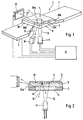
- the analysis element 1 shown in FIGS. 1 and 2 is designed as a test strip 2. It consists of one base strip 3 and made of rigid plastic a test field 4 attached to it shown case only a test layer 5, which with a Foil piece 6 is firmly connected.
- a drop of sample liquid is used to perform an analysis applied to the top 8 of the test layer 5.
- the liquid penetrates, dissolving the in the Test layer 5 contained reagents until they on the Bottom 9 of the test layer 5, the top 10 of the film piece 6 contacted.
- the reaction of the analyte contained in the sample leads to an optically measurable change, especially one Color change, the Teet Mrs 5.
- a light source 11 for example a light-emitting diode
- the evaluation device on the primary light 13 by a below of the test field 4 provided hole 12 of the base strip 3 directed to the underside 14 of the film piece 6 is.
- the test layer 5 through that Film piece 6 diffusely reflected by arrows 15 symbolized secondary light is from a light receiver 16 converted into measurement signals by an evaluation electronics 17 for information about the present or Concentration of the analyte in the sample processed become.
- a light receiver 22 is provided to detect light, which is also connected to the evaluation electronics 17 is. To distinguish it from the measuring receiver 16 he is hereinafter referred to as control recipient 22.
- the name for his light signal is below "Transverse signal” used while the signal of the Measuring receiver 16 is referred to as a "reflectance signal”.
- the control receiver 22 must be designed and arranged in this way be that it selectively detects secondary light that emerges from the peripheral surface 20.
- the evaluation device 23 shown in FIG. 3 has a test strip holder 24, through which the test strip 2 in a defined measuring position is held.
- a suitable one Test strip holder is for example in the US patent 5,424,035.
- the control recipient 22 is like this positioned that its photosensitive surface is dense is arranged at the peripheral surface 20.
- Appropriate means are provided to prevent interference from others Light sources, especially from scattered primary light or to minimize by ambient light. This can be done in a known way Way by means of screens, light barriers and one closing the analysis element holder 24 in a light-tight manner Cover happen. It may also be appropriate to use frequency modulation Primary light and one on the modulation frequency to use a coordinated detection method.
- test field shown in the figures - as general usual - has a rectangular shape, there is the peripheral surface 20 out of four each between the corners of the Rectangular partial areas 20a to 20d.
- a second control recipient is shown in broken lines in FIG 25 indicated, which is designed analogously to the control receiver 22 and on the opposite side of the test field 4 is positioned so that the two side Subareas 20a and 20c of the peripheral surface 20 of the Film piece 6 emerging light can be detected.
- the two are remaining (front and rear) partial surfaces of the peripheral surface not accessible because of a hot melt adhesive strip 26 are closed, for attachment of the test field 4 on the base strip 3.
- the peripheral surface 20 emerging light it can be advantageous be at least a part of the other partial areas 20b to 20d mirror the peripheral surface 20 so that the light reflected from the mirrored areas towards the control receiver 22 from the peripheral surface 20 exits.
- Fig. 4 shows the course of the light signal during the Absorbing the liquid into the test layer 5. Shown is the intensity I (tension of the amplified Signals in volts) as a function of time t (measured in seconds).
- the top dashed line shows the remission signal, i.e. that detected by the measuring receiver 16 Intensity of the diffusely reflected secondary light.
- the solid bottom line shows the transverse signal, d. H. the intensity of that from the control recipient 22 detected from the peripheral surface 20 emerging secondary light. Both light signals were amplified with identical amplifiers. Arrows 28 denote the time at which the surface of the test layer 5 has been contacted with the sample liquid.
- the intensity of the remission signal is twice as high like that of the transversal signal. For the measurement accuracy is however much more important that the relative signal change of the transverse signal much larger than that of the Remission signal is.
- the remission signal drops to Time of fluid intake so little (on average over five series of measurements by about 1.3%) that only large Difficulties can be reliably evaluated.
- the transversal signal increases during soaking up of the liquid in the test layer is essential stronger (about 5% on average over five measurements). This increase can be evaluated relatively easily and reliably become.
- the inventors should the effect on which the invention is based be that by wetting the test layer 5 and thus the top 10 of the film piece facing her 6 the conditions for decoupling light be changed from the piece of film. Part of that in that Film piece penetrating primary light 13 is (depending from the angle of incidence) at the interfaces of the film piece 6 totally reflected.
- the piece of film thus acts in the to some extent as a light guide.
- the totally reflected Light emerges at the peripheral surface 20 and can be as described can be detected.
- Fig. 5 correspond in all respects to Fig. 4 except that the test layer 5 not with blood but with distilled Water was contacted. While that is dashed represented remission signal only a small barely perceptible Burglary at the time of contacting the sample liquid shows is for the transversal signal in this case too, a clear, easily measurable Determine signal change. This shows that the Invention is particularly suitable in cases where which the sample liquid does not or only very weakly is colored.
- test layer 4 on that facing away from the light source 11 Positioned the piece of film 6, the Test layer is thus illuminated through the piece of film. It is not a problem if the in Contact to the film piece 6 standing test layer 5 one or several further layers are provided.
- the test field 4 can have three layers, the first of which to separate the red blood cells serves, the second contains a reagent, the one Pre-reaction causes and the third with the film piece 6 layer in contact is a color reaction layer which is the reagents required for the color reaction contains.
- the liquid their inclusion in the layer adjacent to the film piece to be checked not necessarily the original one Is sample liquid. Rather, it can one already changed by preparatory steps Sample liquid (especially to remove the red Blood cells from blood).
- An analysis element 30 is shown with Longitudinal liquid transport, in which on a base strip 3 at least several test layers 31 to 33 are partially arranged side by side so that one on the first test layer 31 on given sample liquid similar to a chromatography process along the Test layers (from left to right in the figure) in an evaluation zone is transported in which one for the Analysis required detection reaction takes place. Further details of such an analysis element type are described, for example, in US Pat. No. 5,110,550.
- the control of fluid intake also relates in this case the last test layer in the direction of flow.
- the flow path of the liquid ends at the in the figure right end of the test layer 32.
- the reference number 34 denotes a hot melt adhesive strip, by means of a transparent film piece 35 is attached, the relatively stiff, so that the right part of the Test layer 32 and the test layer located below 33 are held down by the film piece 35.
- the film piece 35 is therefore also used as a hold-down layer designated.
- This is an example of that the invention is also suitable in cases where the required Contact between the test layer 33 and the film piece 35 not by coating or any other immediate Connection, but in other ways, for example with an adhesive strip provided on the edge, will be produced.
Landscapes
- Life Sciences & Earth Sciences (AREA)
- Health & Medical Sciences (AREA)
- Immunology (AREA)
- Pathology (AREA)
- Analytical Chemistry (AREA)
- Biochemistry (AREA)
- General Health & Medical Sciences (AREA)
- General Physics & Mathematics (AREA)
- Physics & Mathematics (AREA)
- Chemical & Material Sciences (AREA)
- Molecular Biology (AREA)
- Investigating Or Analysing Materials By The Use Of Chemical Reactions (AREA)
- Investigating Or Analysing Biological Materials (AREA)
- Investigating Or Analysing Materials By Optical Means (AREA)
- Sampling And Sample Adjustment (AREA)
- Investigating Or Analyzing Non-Biological Materials By The Use Of Chemical Means (AREA)
Applications Claiming Priority (2)
| Application Number | Priority Date | Filing Date | Title |
|---|---|---|---|
| DE19926931 | 1999-06-14 | ||
| DE19926931A DE19926931A1 (de) | 1999-06-14 | 1999-06-14 | Verfahren und Vorrichtung zur Kontrolle der Flüssigkeitsaufnahme einer Testschicht eines Analyseelementes |
Publications (3)
| Publication Number | Publication Date |
|---|---|
| EP1061371A2 true EP1061371A2 (fr) | 2000-12-20 |
| EP1061371A3 EP1061371A3 (fr) | 2001-09-26 |
| EP1061371B1 EP1061371B1 (fr) | 2008-07-02 |
Family
ID=7911092
Family Applications (1)
| Application Number | Title | Priority Date | Filing Date |
|---|---|---|---|
| EP00111467A Expired - Lifetime EP1061371B1 (fr) | 1999-06-14 | 2000-05-27 | Méthode et dispositif pour contrôler l'absorption d'un liquide par la couche d'essai d'un élément d'analyse |
Country Status (5)
| Country | Link |
|---|---|
| US (1) | US6362890B1 (fr) |
| EP (1) | EP1061371B1 (fr) |
| JP (1) | JP2001004540A (fr) |
| AT (1) | ATE399994T1 (fr) |
| DE (2) | DE19926931A1 (fr) |
Cited By (1)
| Publication number | Priority date | Publication date | Assignee | Title |
|---|---|---|---|---|
| EP1240503B1 (fr) * | 1999-12-24 | 2018-01-17 | Roche Diabetes Care GmbH | Système d'analyse pour une bande de test, bande de test médical, et procédé d'analyse d'un échantillon à l'aide d'un système d'analyse pour une bande de test |
Families Citing this family (13)
| Publication number | Priority date | Publication date | Assignee | Title |
|---|---|---|---|---|
| US6521182B1 (en) * | 1998-07-20 | 2003-02-18 | Lifescan, Inc. | Fluidic device for medical diagnostics |
| US6830934B1 (en) * | 1999-06-15 | 2004-12-14 | Lifescan, Inc. | Microdroplet dispensing for a medical diagnostic device |
| US20020140940A1 (en) * | 2001-02-28 | 2002-10-03 | Bambot Shabbir B. | System and method for measurement and analysis of a sample by absorption spectrophotometry |
| DE10164358C2 (de) * | 2001-12-28 | 2003-11-27 | Advalytix Ag | Charakterisierungsverfahren für funktionalisierte Oberflächen |
| US6731387B2 (en) * | 2002-02-06 | 2004-05-04 | Alexander V. Neimark | Light beam measurement of absorption by substrates |
| KR20030069486A (ko) * | 2002-02-20 | 2003-08-27 | 엘지전자 주식회사 | 테스트 스트립의 광학적 분석장치 |
| DE10248555B4 (de) * | 2002-10-18 | 2004-12-02 | Roche Diagnostics Gmbh | Verfahren und Analysesystem zur Ermittlung der Konzentration eines Analyten in einer Probe, die aus dem Analyten und der Probenmatrix besteht und Testelement dafür |
| WO2005072398A2 (fr) * | 2004-01-28 | 2005-08-11 | Bamburgh Marrsh Llc | Dispositif de collecte et systeme de test d'echantillon de prelevement |
| US20060002817A1 (en) * | 2004-06-30 | 2006-01-05 | Sebastian Bohm | Flow modulation devices |
| US20060000710A1 (en) * | 2004-06-30 | 2006-01-05 | Klaus Peter Weidenhaupt | Fluid handling methods |
| US20060000709A1 (en) * | 2004-06-30 | 2006-01-05 | Sebastian Bohm | Methods for modulation of flow in a flow pathway |
| US20060001551A1 (en) * | 2004-06-30 | 2006-01-05 | Ulrich Kraft | Analyte monitoring system with wireless alarm |
| EP1760469A1 (fr) * | 2005-09-01 | 2007-03-07 | F.Hoffmann-La Roche Ag | Dispositif de test pour fluides corporels avec un élément optique tournant |
Family Cites Families (18)
| Publication number | Priority date | Publication date | Assignee | Title |
|---|---|---|---|---|
| US3907503A (en) * | 1974-01-21 | 1975-09-23 | Miles Lab | Test system |
| WO1983000931A1 (fr) * | 1981-09-08 | 1983-03-17 | Eastman Kodak Co | Procede et dispositif de detection de fluide d'echantillon |
| AU588245B2 (en) * | 1984-06-13 | 1989-09-14 | Inverness Medical Switzerland Gmbh | Devices for use in chemical test procedures |
| US4935346A (en) * | 1986-08-13 | 1990-06-19 | Lifescan, Inc. | Minimum procedure system for the determination of analytes |
| DE3721237A1 (de) * | 1987-06-27 | 1989-01-05 | Boehringer Mannheim Gmbh | Diagnostischer testtraeger und verfahren zu dessen herstellung |
| DE3725766A1 (de) * | 1987-08-04 | 1989-02-16 | Boehringer Mannheim Gmbh | Testtraeger zur bestimmung eines analyten aus blut und verfahren zu seiner herstellung |
| DE3844104A1 (de) | 1988-12-28 | 1990-07-05 | Boehringer Mannheim Gmbh | Testtraeger-analysesystem |
| US5114350A (en) * | 1989-03-08 | 1992-05-19 | Cholestech Corporation | Controlled-volume assay apparatus |
| DE59001976D1 (de) * | 1989-05-01 | 1993-08-19 | Wolfram Bohnenkamp | Reflexionsfluorimeter. |
| DE59206122D1 (de) * | 1991-02-28 | 1996-05-30 | Boehringer Mannheim Gmbh | Testträger zur bestimmung eines analyten aus vollblut |
| DE4227665A1 (de) * | 1992-08-21 | 1994-02-24 | Boehringer Mannheim Gmbh | Analyseelement zur Analyse einer flüssigen Probe |
| DE4305058C2 (de) * | 1993-02-19 | 2001-04-12 | Roche Diagnostics Gmbh | Testträger-Analysesystem zur Analyse eines Bestandteils einer flüssigen Probe |
| GB2276003B (en) | 1993-03-09 | 1997-01-08 | Spectra Tech Inc | Method and apparatus for enhancing the usefulness of infrared transmitting materials |
| DE4310583A1 (de) * | 1993-03-31 | 1994-10-06 | Boehringer Mannheim Gmbh | Teststreifenanalysesystem |
| DE4321548A1 (de) | 1993-06-29 | 1995-01-12 | Boehringer Mannheim Gmbh | Verfahren zum Erfassen und Auswerten analoger photometrischer Signale in einem Testträger-Analysesystem und Anordnung zur Durchführung des Verfahrens |
| DE19628562A1 (de) * | 1996-07-16 | 1998-01-22 | Boehringer Mannheim Gmbh | Analysesystem mit Mitteln zur Erkennung von Unterdosierungen |
| US6093156A (en) * | 1996-12-06 | 2000-07-25 | Abbott Laboratories | Method and apparatus for obtaining blood for diagnostic tests |
| US6084660A (en) * | 1998-07-20 | 2000-07-04 | Lifescan, Inc. | Initiation of an analytical measurement in blood |
-
1999
- 1999-06-14 DE DE19926931A patent/DE19926931A1/de not_active Withdrawn
-
2000
- 2000-05-27 AT AT00111467T patent/ATE399994T1/de not_active IP Right Cessation
- 2000-05-27 DE DE50015232T patent/DE50015232D1/de not_active Expired - Fee Related
- 2000-05-27 EP EP00111467A patent/EP1061371B1/fr not_active Expired - Lifetime
- 2000-06-05 JP JP2000167508A patent/JP2001004540A/ja not_active Ceased
- 2000-06-09 US US09/591,269 patent/US6362890B1/en not_active Expired - Fee Related
Cited By (1)
| Publication number | Priority date | Publication date | Assignee | Title |
|---|---|---|---|---|
| EP1240503B1 (fr) * | 1999-12-24 | 2018-01-17 | Roche Diabetes Care GmbH | Système d'analyse pour une bande de test, bande de test médical, et procédé d'analyse d'un échantillon à l'aide d'un système d'analyse pour une bande de test |
Also Published As
| Publication number | Publication date |
|---|---|
| EP1061371B1 (fr) | 2008-07-02 |
| JP2001004540A (ja) | 2001-01-12 |
| US6362890B1 (en) | 2002-03-26 |
| ATE399994T1 (de) | 2008-07-15 |
| DE50015232D1 (de) | 2008-08-14 |
| DE19926931A1 (de) | 2000-12-21 |
| EP1061371A3 (fr) | 2001-09-26 |
Similar Documents
| Publication | Publication Date | Title |
|---|---|---|
| EP1240503B1 (fr) | Système d'analyse pour une bande de test, bande de test médical, et procédé d'analyse d'un échantillon à l'aide d'un système d'analyse pour une bande de test | |
| EP1238274B1 (fr) | Systeme d'analyse pour element d'essai, dote d'un detecteur infrarouge | |
| DE60018537T2 (de) | Teststreifen zur Bestimmung eines Analyts in eine flüssige Probe | |
| DE69221306T2 (de) | Methode zur photometrischen (in vitro) bestimmung des gehaltes eines analyts in einer probe | |
| DE102004027132B4 (de) | Frühe Bestimmung von Assayergebnissen | |
| DE69513409T2 (de) | Analytischer nachweisstreifen mit orientierungsindex | |
| DE2613617C2 (de) | Verfahren zur Analyse von Proben, z.B. Urin | |
| DE2723183C3 (de) | Prüfmittel zur Bestimmung von Hämoglobin in einer Blutprobe | |
| DE69431334T2 (de) | Vorrichtung zum Ablesen von Teststreifen | |
| DE69612126T2 (de) | Testträger und Verfahren zur quantitatieven NIR spektroskopischen Analyse | |
| DE69218966T2 (de) | Verbessertes nichtinvasives quantitatives messinstrument im nahen infrarot | |
| DE69025110T2 (de) | Testgerät | |
| EP1061371B1 (fr) | Méthode et dispositif pour contrôler l'absorption d'un liquide par la couche d'essai d'un élément d'analyse | |
| DE10163775A1 (de) | Analysensystem zur Bestimmung einer Analytkonzentration unter Berücksichtigung von proben- und analytunabhängigen Lichtintensitätsänderungen | |
| EP0819943A2 (fr) | Système d'analyse avec moyens de détection d'un dosage insuffisant | |
| EP0105211A1 (fr) | Cuvette pour déterminer les composés chimiques dans des liquides | |
| EP0309883B1 (fr) | Bande d'analyse pour la détermination d'un composant dans un fluide corporel | |
| DE102004027130B4 (de) | Flussabtasten zur Bestimmung von Assayergebnissen | |
| EP2060906A1 (fr) | Procédé d'évaluation photométrique d'éléments test | |
| DE19544501A1 (de) | Vorrichtung für Lichtreflexionsmessungen | |
| EP0376110A2 (fr) | Analyseur pour bandes de test | |
| EP2116180A1 (fr) | Unité de bande diagnostic et système de mesure diagnostic | |
| EP1921441B1 (fr) | Appareil d'analyse d'un élément de test d'échantillon et système d'analyse | |
| DE4314835A1 (de) | Verfahren und Vorrichtung zur Analyse von Glucose in einer biologischen Matrix | |
| DE19628562A1 (de) | Analysesystem mit Mitteln zur Erkennung von Unterdosierungen |
Legal Events
| Date | Code | Title | Description |
|---|---|---|---|
| PUAI | Public reference made under article 153(3) epc to a published international application that has entered the european phase |
Free format text: ORIGINAL CODE: 0009012 |
|
| 17P | Request for examination filed |
Effective date: 20000527 |
|
| AK | Designated contracting states |
Kind code of ref document: A2 Designated state(s): AT BE CH CY DE DK ES FI FR GB GR IE IT LI LU MC NL PT SE |
|
| AX | Request for extension of the european patent |
Free format text: AL;LT;LV;MK;RO;SI |
|
| RIN1 | Information on inventor provided before grant (corrected) |
Inventor name: RUPPENDER, UWE Inventor name: PETRICH, WOLFGANG, DR. Inventor name: VOELKEL,DIRK,DR. |
|
| PUAL | Search report despatched |
Free format text: ORIGINAL CODE: 0009013 |
|
| AK | Designated contracting states |
Kind code of ref document: A3 Designated state(s): AT BE CH CY DE DK ES FI FR GB GR IE IT LI LU MC NL PT SE |
|
| AX | Request for extension of the european patent |
Free format text: AL;LT;LV;MK;RO;SI |
|
| RIC1 | Information provided on ipc code assigned before grant |
Free format text: 7G 01N 35/00 A, 7G 01N 21/86 B, 7G 01N 21/55 B |
|
| AKX | Designation fees paid |
Free format text: AT BE CH CY DE DK ES FI FR GB GR IE IT LI LU MC NL PT SE |
|
| GRAP | Despatch of communication of intention to grant a patent |
Free format text: ORIGINAL CODE: EPIDOSNIGR1 |
|
| GRAS | Grant fee paid |
Free format text: ORIGINAL CODE: EPIDOSNIGR3 |
|
| GRAA | (expected) grant |
Free format text: ORIGINAL CODE: 0009210 |
|
| AK | Designated contracting states |
Kind code of ref document: B1 Designated state(s): AT BE CH CY DE DK ES FI FR GB GR IE IT LI LU MC NL PT SE |
|
| REG | Reference to a national code |
Ref country code: GB Ref legal event code: FG4D Free format text: NOT ENGLISH |
|
| REG | Reference to a national code |
Ref country code: CH Ref legal event code: EP |
|
| REF | Corresponds to: |
Ref document number: 50015232 Country of ref document: DE Date of ref document: 20080814 Kind code of ref document: P |
|
| REG | Reference to a national code |
Ref country code: IE Ref legal event code: FG4D Free format text: LANGUAGE OF EP DOCUMENT: GERMAN |
|
| PG25 | Lapsed in a contracting state [announced via postgrant information from national office to epo] |
Ref country code: NL Free format text: LAPSE BECAUSE OF FAILURE TO SUBMIT A TRANSLATION OF THE DESCRIPTION OR TO PAY THE FEE WITHIN THE PRESCRIBED TIME-LIMIT Effective date: 20080702 |
|
| NLV1 | Nl: lapsed or annulled due to failure to fulfill the requirements of art. 29p and 29m of the patents act | ||
| PG25 | Lapsed in a contracting state [announced via postgrant information from national office to epo] |
Ref country code: PT Free format text: LAPSE BECAUSE OF FAILURE TO SUBMIT A TRANSLATION OF THE DESCRIPTION OR TO PAY THE FEE WITHIN THE PRESCRIBED TIME-LIMIT Effective date: 20081202 Ref country code: ES Free format text: LAPSE BECAUSE OF FAILURE TO SUBMIT A TRANSLATION OF THE DESCRIPTION OR TO PAY THE FEE WITHIN THE PRESCRIBED TIME-LIMIT Effective date: 20081013 |
|
| REG | Reference to a national code |
Ref country code: IE Ref legal event code: FD4D |
|
| PG25 | Lapsed in a contracting state [announced via postgrant information from national office to epo] |
Ref country code: FI Free format text: LAPSE BECAUSE OF FAILURE TO SUBMIT A TRANSLATION OF THE DESCRIPTION OR TO PAY THE FEE WITHIN THE PRESCRIBED TIME-LIMIT Effective date: 20080702 |
|
| PG25 | Lapsed in a contracting state [announced via postgrant information from national office to epo] |
Ref country code: IE Free format text: LAPSE BECAUSE OF FAILURE TO SUBMIT A TRANSLATION OF THE DESCRIPTION OR TO PAY THE FEE WITHIN THE PRESCRIBED TIME-LIMIT Effective date: 20080702 Ref country code: DK Free format text: LAPSE BECAUSE OF FAILURE TO SUBMIT A TRANSLATION OF THE DESCRIPTION OR TO PAY THE FEE WITHIN THE PRESCRIBED TIME-LIMIT Effective date: 20080702 |
|
| PLBE | No opposition filed within time limit |
Free format text: ORIGINAL CODE: 0009261 |
|
| STAA | Information on the status of an ep patent application or granted ep patent |
Free format text: STATUS: NO OPPOSITION FILED WITHIN TIME LIMIT |
|
| 26N | No opposition filed |
Effective date: 20090403 |
|
| PG25 | Lapsed in a contracting state [announced via postgrant information from national office to epo] |
Ref country code: IT Free format text: LAPSE BECAUSE OF FAILURE TO SUBMIT A TRANSLATION OF THE DESCRIPTION OR TO PAY THE FEE WITHIN THE PRESCRIBED TIME-LIMIT Effective date: 20080702 |
|
| PGFP | Annual fee paid to national office [announced via postgrant information from national office to epo] |
Ref country code: DE Payment date: 20090529 Year of fee payment: 10 Ref country code: FR Payment date: 20090507 Year of fee payment: 10 |
|
| BERE | Be: lapsed |
Owner name: ROCHE DIAGNOSTICS G.M.B.H. Effective date: 20090531 |
|
| PGFP | Annual fee paid to national office [announced via postgrant information from national office to epo] |
Ref country code: GB Payment date: 20090407 Year of fee payment: 10 |
|
| PG25 | Lapsed in a contracting state [announced via postgrant information from national office to epo] |
Ref country code: MC Free format text: LAPSE BECAUSE OF NON-PAYMENT OF DUE FEES Effective date: 20090531 |
|
| REG | Reference to a national code |
Ref country code: CH Ref legal event code: PL |
|
| PG25 | Lapsed in a contracting state [announced via postgrant information from national office to epo] |
Ref country code: SE Free format text: LAPSE BECAUSE OF FAILURE TO SUBMIT A TRANSLATION OF THE DESCRIPTION OR TO PAY THE FEE WITHIN THE PRESCRIBED TIME-LIMIT Effective date: 20081002 Ref country code: CH Free format text: LAPSE BECAUSE OF NON-PAYMENT OF DUE FEES Effective date: 20090531 Ref country code: LI Free format text: LAPSE BECAUSE OF NON-PAYMENT OF DUE FEES Effective date: 20090531 |
|
| PG25 | Lapsed in a contracting state [announced via postgrant information from national office to epo] |
Ref country code: BE Free format text: LAPSE BECAUSE OF NON-PAYMENT OF DUE FEES Effective date: 20090531 |
|
| PG25 | Lapsed in a contracting state [announced via postgrant information from national office to epo] |
Ref country code: AT Free format text: LAPSE BECAUSE OF NON-PAYMENT OF DUE FEES Effective date: 20090527 |
|
| PG25 | Lapsed in a contracting state [announced via postgrant information from national office to epo] |
Ref country code: GR Free format text: LAPSE BECAUSE OF FAILURE TO SUBMIT A TRANSLATION OF THE DESCRIPTION OR TO PAY THE FEE WITHIN THE PRESCRIBED TIME-LIMIT Effective date: 20081003 |
|
| GBPC | Gb: european patent ceased through non-payment of renewal fee |
Effective date: 20100527 |
|
| REG | Reference to a national code |
Ref country code: FR Ref legal event code: ST Effective date: 20110131 |
|
| PG25 | Lapsed in a contracting state [announced via postgrant information from national office to epo] |
Ref country code: LU Free format text: LAPSE BECAUSE OF NON-PAYMENT OF DUE FEES Effective date: 20090527 Ref country code: DE Free format text: LAPSE BECAUSE OF NON-PAYMENT OF DUE FEES Effective date: 20101201 |
|
| PG25 | Lapsed in a contracting state [announced via postgrant information from national office to epo] |
Ref country code: FR Free format text: LAPSE BECAUSE OF NON-PAYMENT OF DUE FEES Effective date: 20100531 |
|
| PG25 | Lapsed in a contracting state [announced via postgrant information from national office to epo] |
Ref country code: GB Free format text: LAPSE BECAUSE OF NON-PAYMENT OF DUE FEES Effective date: 20100527 |
|
| PG25 | Lapsed in a contracting state [announced via postgrant information from national office to epo] |
Ref country code: CY Free format text: LAPSE BECAUSE OF FAILURE TO SUBMIT A TRANSLATION OF THE DESCRIPTION OR TO PAY THE FEE WITHIN THE PRESCRIBED TIME-LIMIT Effective date: 20080702 |