EP1061470A2 - Transporteinrichtung für Informationsträger, insbesondere Karten - Google Patents
Transporteinrichtung für Informationsträger, insbesondere Karten Download PDFInfo
- Publication number
- EP1061470A2 EP1061470A2 EP00104031A EP00104031A EP1061470A2 EP 1061470 A2 EP1061470 A2 EP 1061470A2 EP 00104031 A EP00104031 A EP 00104031A EP 00104031 A EP00104031 A EP 00104031A EP 1061470 A2 EP1061470 A2 EP 1061470A2
- Authority
- EP
- European Patent Office
- Prior art keywords
- transport device
- belt
- information carrier
- belt drive
- area
- Prior art date
- Legal status (The legal status is an assumption and is not a legal conclusion. Google has not performed a legal analysis and makes no representation as to the accuracy of the status listed.)
- Granted
Links
Images


Classifications
-
- B—PERFORMING OPERATIONS; TRANSPORTING
- B65—CONVEYING; PACKING; STORING; HANDLING THIN OR FILAMENTARY MATERIAL
- B65G—TRANSPORT OR STORAGE DEVICES, e.g. CONVEYORS FOR LOADING OR TIPPING, SHOP CONVEYOR SYSTEMS OR PNEUMATIC TUBE CONVEYORS
- B65G15/00—Conveyors having endless load-conveying surfaces, i.e. belts and like continuous members, to which tractive effort is transmitted by means other than endless driving elements of similar configuration
- B65G15/10—Conveyors having endless load-conveying surfaces, i.e. belts and like continuous members, to which tractive effort is transmitted by means other than endless driving elements of similar configuration comprising two or more co-operating endless surfaces with parallel longitudinal axes, or a multiplicity of parallel elements, e.g. ropes defining an endless surface
- B65G15/12—Conveyors having endless load-conveying surfaces, i.e. belts and like continuous members, to which tractive effort is transmitted by means other than endless driving elements of similar configuration comprising two or more co-operating endless surfaces with parallel longitudinal axes, or a multiplicity of parallel elements, e.g. ropes defining an endless surface with two or more endless belts
- B65G15/14—Conveyors having endless load-conveying surfaces, i.e. belts and like continuous members, to which tractive effort is transmitted by means other than endless driving elements of similar configuration comprising two or more co-operating endless surfaces with parallel longitudinal axes, or a multiplicity of parallel elements, e.g. ropes defining an endless surface with two or more endless belts the load being conveyed between the belts
-
- G—PHYSICS
- G06—COMPUTING OR CALCULATING; COUNTING
- G06K—GRAPHICAL DATA READING; PRESENTATION OF DATA; RECORD CARRIERS; HANDLING RECORD CARRIERS
- G06K13/00—Conveying record carriers from one station to another, e.g. from stack to punching mechanism
- G06K13/02—Conveying record carriers from one station to another, e.g. from stack to punching mechanism the record carrier having longitudinal dimension comparable with transverse dimension, e.g. punched card
- G06K13/06—Guiding cards; Checking correct operation of card-conveying mechanisms
-
- G—PHYSICS
- G06—COMPUTING OR CALCULATING; COUNTING
- G06K—GRAPHICAL DATA READING; PRESENTATION OF DATA; RECORD CARRIERS; HANDLING RECORD CARRIERS
- G06K13/00—Conveying record carriers from one station to another, e.g. from stack to punching mechanism
- G06K13/02—Conveying record carriers from one station to another, e.g. from stack to punching mechanism the record carrier having longitudinal dimension comparable with transverse dimension, e.g. punched card
- G06K13/07—Transporting of cards between stations
-
- G—PHYSICS
- G06—COMPUTING OR CALCULATING; COUNTING
- G06K—GRAPHICAL DATA READING; PRESENTATION OF DATA; RECORD CARRIERS; HANDLING RECORD CARRIERS
- G06K17/00—Methods or arrangements for effecting co-operative working between equipments covered by two or more of main groups G06K1/00 - G06K15/00, e.g. automatic card files incorporating conveying and reading operations
-
- B—PERFORMING OPERATIONS; TRANSPORTING
- B65—CONVEYING; PACKING; STORING; HANDLING THIN OR FILAMENTARY MATERIAL
- B65G—TRANSPORT OR STORAGE DEVICES, e.g. CONVEYORS FOR LOADING OR TIPPING, SHOP CONVEYOR SYSTEMS OR PNEUMATIC TUBE CONVEYORS
- B65G2201/00—Indexing codes relating to handling devices, e.g. conveyors, characterised by the type of product or load being conveyed or handled
- B65G2201/02—Articles
Definitions
- the invention relates to a transport device for information carriers, in particular cards, otherwise mentioned in the preamble of claim 1 Art.
- Transport devices of this type are known (DE 196 10 030 C2, EP 0 623 894 A1), which, however, is suitable for high-performance transport, i.e. e.g. with a throughput of e.g. about 40,000 to 48,000 information carriers per Hour, are unsuitable because they are not reliable at this high performance Enable coding of the information carriers.
- the invention has for its object a transport device type mentioned in such a way that these even with very large Transport performance and high throughput a reliable, trouble-free Coding of the information carriers transported through is guaranteed.
- the part of a transport device 10 that is of interest here shown which is intended for information carriers 11, in particular for cards.
- the Information carriers 11 of the same type are e.g. on their top in Fig. 1 Top 12 at least on part of the surface with a schematic indicated, longitudinal magnetic strips 13 are provided and at Passage through the transport device 10 on its bottom in Fig. 1 running underside and / or printed on its top 12 or with other information.
- This also means that the individual Information carrier 11 on at least one coding head, here z. B. past two coding heads 14 and 15 , e.g. the first placed in the direction of transport Coding head 14 as a write head and the other coding head 15 as a read head act.
- the magnetic strip 13 is also corresponding information described on the magnetic stripe 13th are stored and read by the coding head 15 functioning as a reading head and checked when the information carrier 11 on this coding head 15 is moved past.
- information carriers in particular magnetic cards, is it e.g. credit cards, phone cards, customer cards or the like Cards with information that can be stored.
- the transport device 10 is part of an otherwise not shown machine that is modular. Machines of this type in training according to the Invention have a performance of approximately 40,000 to 48,000 pieces per hour.
- the transport device 10 has a schematically indicated, linear running transport route 20 on which the information carrier 11 is resting be taken along and transported forward.
- the transport route 20 has a longitudinally driven in the direction of arrow 16 belt 21, which with Carriers 22 is provided, which are arranged at predetermined intervals and protrude up over the top of the belt 21.
- Driver 22 is visibly dimensioned larger than the length of the respective information carrier 11.
- the width of the band 21 is narrower measured as the width of the respective information carrier 11.
- the band 21 is made of a belt e.g. made of rubber or synthetic rubber or plastic or the like. educated.
- the drivers 22 consist of towering Crosspieces that can extend over the entire width of the belt 21.
- the two Longitudinal guides 23, 24 run approximately parallel to the band 21 and extend in Fig. 1 approximately up to an inlet area 26 of a second transport device 30, which is a modular part of the transport device 10 and the machine.
- Each Longitudinal guide 23, 24 has on the side that of the assigned longitudinal edge 18 or 25 of the respective information carrier 11 is facing, an L-profile or instead a U-profile directed to the side and open to the side.
- an L-profile or instead a U-profile directed to the side and open to the side.
- each on the rear transverse edge 27 of each information carrier 11 can be Already a certain alignment and stabilization of the tape 21 individual information carrier 11 reached.
- each information carrier 11 work together becomes a reliable Longitudinal guidance without transverse offset of the individual information carriers 11 at Forward transport on belt 21 guaranteed.
- the transport device 30 is located laterally next to the band 21 and is approximately parallel to this arranged, the transport device 30 on that side of the belt 21 runs, the surface strip 18 and the magnetic strip 13 and the Long edge 19 faces, that is in Fig. 1 on the one running up there Long side of the belt 21.
- the respective information carrier 11 is on the tape 21 in this way can be transported lying on up to the inlet area 26 of the transport device 30 and in this inlet area 26 and to this transport device 30 below complete decoupling from the tape 21 can be transferred, the information carrier 11 then, viewed in the direction of transport according to arrow 16, towards from towards Driver 22 is discontinued.
- the Speed difference is e.g. chosen such that the respective in the inlet area 26 detected by the transport device 30 and transported forward Information carrier 11 in the longitudinal direction of the tape 21 with its transverse edge 27 from the carrier 22, which was in contact with it up to that point, to the side becomes.
- the speed difference between the speed of the Belt 21 and that of the transport device 30 is selected such that the respective information carrier 11 when it is in the entry area 26 opposite outlet area 31 from the transport device 30 again is released on a between two drivers 22 of the belt 21st lying band area is passed to the belt 21 and then on this lying forward is moved forward.
- the transport speed of the Transport device 30 can e.g.
- both the surface strip 18 and the area of the magnetic strip 13 on the top 12 free, so that both when reaching the inlet area 26 of the transport device 30 are accessible, namely the area strip 18 for detecting and clamping the information carrier 11 by means of the Transport device 30 and the area of the magnetic strip 13 subject to change the purpose that each information carrier 11 on the coding heads 14 and 15 can be moved past such that the area of the coding heads 14, 15 of the magnetic strip 13 can be written or read.
- This transport device 30 has at least one belt drive 32 with an endless belt 33, which is spaced apart from one another on a housing 34 arranged, rotatable deflection rollers 35, 36 is guided.
- the lower strand in Fig. 2 37 of the endless belt 33 can be in the area of the indicated area strip 18 on the top 12 of each information carrier 11 to the surface create this.
- the transport device 30 also has a belt drive 32 opposite, generally designated 38 counterholder on the one strand 37 with clamping and further transport of a retracted one Information carrier 11 can be applied.
- This counter holder 38 can be used Not shown embodiment from a plate or bar or at least one role or the like consist.
- the counter-holder 38 as the second corresponding to the first belt drive 32
- Belt drive 39 formed, which also has an endless belt 40, the via two rotatable and spaced apart on the housing 34 Deflection rollers 41, 42 is guided, the upper strand 43 in FIG other run 37 of the first belt drive 32 with clamping and further transport of a confiscated information carrier 11 can be present.
- Each belt drive 32, 39 has a tension roller for the endless belt 33 or 40 44 or 45 of the usual type.
- the clamping distance between the at least one belt drive 32 and the Bracket 38, in particular second belt drive 39, is adjustable so that an adjustment to different cross-sectional thicknesses of the information carriers 11, e.g. in the order of magnitude between 0.25 mm and 1.5 mm.
- the first belt drive 32 is geared with the second belt drive 39 Medium geared and synchronized, which here consists of two in each other Engaging gears 46 and 47 exist.
- the at least one Belt drive e.g. the first belt drive 32 is by means of an electric Drive motor 48, in particular servo motor, driven via a pinion 49, that e.g. can be directly engaged with a gear 46.
- the Speed of the first belt drive 32, in particular of the endless belt 33 is adjustable, e.g. in that the speed of the drive motor 48 in Depending on the speed of the belt 21, preferably by means of a the respective tape encoder 50 is controlled.
- the respective endless belt 33 or 40 is designed as a toothed belt and e.g. made of rubber or synthetic rubber or plastic or the like.
- the pulleys 35, 36 and 41, 42 are in adaptation to the respective toothed belt as Gears or sprockets designed to hold the teeth of each Endless belts 33 and 40 are positively engaged.
- the at least one Endless belt 33 of the first belt drive 32 as well as the endless belt 40 the width of the second belt drive 39 is significantly narrower than that Width of the respective information carrier 11 dimensioned so that an between two strands 37 and 43 retracted information carrier 11 along one between the two longitudinal edges 19 and 25 and outside the range of Magnetic stripe 13 located surface strip 18 clamped and transported forward can be.
- the coding heads 14, 15 are along the transport route of the respective information carrier 11 in the transport device 30 and arranged on the length region of the run 37, 43, the Coding heads 14, 15 on the length range between the deflection rollers 35, 36 and 41, 42 are placed.
- the distance between the two coding heads 14, 15 is at least as large as that Length of each information carrier 11. This distance is expedient between the coding heads 14, 15 visibly larger than the length of each Information carrier 11. This leads to the advantage that if there is still in the Area of the coding head 15 is an information carrier 11, not yet Information carrier 11 can get into the area of the coding head 14. In order to is any disruption, especially bumps that otherwise affect the Information carrier 11 could act, prevented.
- Another, essential peculiarity of the transport device 10, in particular the modular transport device 30 of this, is that at least the run 37 of the at least one belt drive 32, which is based on the Top side 12 in the area of the area strip 18 on each information carrier 11 creates, on the side facing away from the information carrier 11, at least permanently or at least temporarily with compressed gas, in particular Compressed air, in the sense of an additional pressure on the run 37 to the Top 12 of the information carrier 12 is applied.
- Embodiment is both in the first belt drive 32 whose run 37 also with the second belt drive 39, its run 43 in a corresponding manner Pressurized gas, in particular compressed air, is applied, the direction of action is such that the two strands 37 and 43 under the effect of Compressed gas, especially the compressed air, are pressed against each other, so that an increased on the respective information carrier 11 clamped between them Clamping force works.
- Pressurized gas in particular compressed air
- This increased clamping force is above the respective pressure of the Compressed gas, especially compressed air, adjustable and causes everyone some caught and clamped between the two strands 37 and 43
- Information carrier 11 then after it from the belt 21 of the transport route 20th was uncoupled, reliable, firm and non-slip in this orientation and clamped vibration-free and along by means of the transport device 30 the coding heads 14, 15 and then back to the tape 21 is delivered.
- the respective one with compressed gas, in particular compressed air, applied strand 37, 43 is not only on a short longitudinal area but essentially all of its free, itself between the respective Deflection rollers 35, 36 or 44, 45 extending length and / or width and here preferably as evenly as possible with compressed gas, in particular compressed air, acted upon.
- the pressure at which the compressed gas flows through the respective run 37, 43 acted upon, is adjustable and with regard to its value to such correspondingly more sufficient, acting on the respective information carrier 11 Adjustable clamping force.
- FIGS. 1 and 2 has the housing 34 on the side of the respective strand 37, 43, which the Information carrier 11 is turned away and pressurized gas is applied, one or more outlet openings 51 on the one hand and 52 on the other hand for the Pressurized gas, e.g. are designed as slot nozzles and each with a associated supply channel 53 and 54 are connected.
- FIGS. 1 and 2 show are in the running direction of the strand 37 each pressurized with compressed gas or 43 a plurality of outlet openings 51, 52, and a large number of such Outlet openings 51, 52, spaced apart.
- these outlet openings 51, 52 are here with their long side in Direction of rotation of the respective run 37 or 43 aligned so that each run 37th or 43 over its length and width as evenly as possible with compressed gas, in particular compressed air.
- the outlet openings 51, 52 as transverse openings, e.g. Slot nozzles, designed, their width e.g. about as large as the width of the respective run 37 or 43 can be.
- 1 and 2 shows a series of outlet openings 51, 52 provided practically the entire length between the two Deflection rollers 35, 36 and 41, 42 extends.
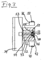
- the respective strand 37 or 43 which is pressurized with compressed gas, is on the a support surface 55 on the side facing away from the respective information carrier 11 or 56 assigned (Fig. 3), which is part of the housing 34 and the Contains outlet openings 51, 52, in particular slot nozzles.
- the respective outlet openings 51, 52 open into the assigned respective support surface 55, 56.
- the individual outlet openings 51 can, in the longitudinal direction of the run 37, viewed via a connecting channel communicate with each other so that only a single feed channel 53 in Housing 34 is necessary to fill these discharge openings 51 with compressed gas, in particular Compressed air. In the same way, the supply of opposite outlet openings 52 take place.
- One strand 37 is included the support surface 55 associated with the outlet openings 51 during the other run 43 the other support surface 56 with the outlet openings 52 is assigned, the outlet openings 51, 52 each on the side of the Trums 37 and 43 open out, the one to be clamped and through information carrier 11 to be transported is facing away.
- the width of the Support surface 55 or 56 can be wider than that of the endless belt 33 or 40 be chosen.
- each contains Support surface 55, 56 a recessed groove 57 and 58, in the bottom surface of the Outlet openings 51 and 52 are included.
- the respective groove 57, 58 has one Width which is approximately that of the associated endless belt 33 or 40 corresponds, the respective groove 57, 58 as a guide for the respective Endless belt 33 or 40 is formed and thus a safe transverse guide for the respective run 37 or 43 causes ..
- the endless belt 33 of the first belt drive runs 32 and the endless belt 40 of the second belt drive 39 in essentially within a common vertical plane, with no Longitudinal offset of the endless belt 33.40 is provided to each other.
- the transport device 30 designed in this way extends approximately in the longitudinal region of the in FIG. 1 upper longitudinal edge of the belt 21 and thereby in the longitudinal region of the in Fig. 1st 3 or the right longitudinal edge of the respective support surface 55, 56 in FIG. 3.
- the one securely and firmly clamped between the strands 37, 43 and held information carrier 11 is thus entirely from the tape 21 uncoupled, so that no possible vibrations originating from there, Forces or the like can act on the information carrier 11.
- the Information carrier 11 is in this way by means of the two belt drives 32, 39 transported from the inlet area 26 towards the outlet area 31, wherein the coding head 14, which acts as a write head, is first passed by means of the corresponding information is stored on the magnetic strip 13 become. Then the coding head 15, which acts as a read head, is passed through, by means of which the stored information is queried and checked.
- the information carrier 11 then arrives at the outlet area 31 and is moved to Leave this in the same orientation again on the top of the Volume 21 delivered, namely with its rear transverse edge 27 in front a driver 22, which then due to the somewhat slower running of the Tap tape 21 on the transverse edge 27 again and thus the information carrier 11 form-fitting, lying on the belt 21, can be transported further.
Landscapes
- Engineering & Computer Science (AREA)
- Physics & Mathematics (AREA)
- General Physics & Mathematics (AREA)
- Theoretical Computer Science (AREA)
- Mechanical Engineering (AREA)
- Delivering By Means Of Belts And Rollers (AREA)
- Conveying Record Carriers (AREA)
- Stacking Of Articles And Auxiliary Devices (AREA)
- Discharge Of Articles From Conveyors (AREA)
Abstract
Description
- Fig. 1
- eine schematische Draufsicht von Teilen einer Transporteinrichtung für Informationsträger,
- Fig. 2
- eine schematische Seitenansicht in Pfeilrichtung II in Fig. 1 einer Einzelheit der Transporteinrichtung in Fig. 1,
- Fig. 3
- einen schematischen Schnitt entlang der Linie III-III in Fig. 2.
Claims (39)
- Transporteinrichtung für Informationsträger, insbesondere Karten, mit zumindest einem Riementrieb (32) mit einem über zwei in Abstand voneinander an einem Gehäuse (34) angeordnete Umlenkrollen (35,36) geführten Endlosriemen (33), dessen einer Trum (37) sich im Bereich eines Flächenstreifens (18) an die Oberfläche des Informationsträgers (11) anlegt, und mit einem dem Riementrieb (32) gegenüberliegenden Gegenhalter (38), an dem der eine Trum (37) unter Klemmung und Weitertransport eines eingezogenen Informationsträgers (11) anliegen kann,
dadurch gekennzeichnet,
daß der Trum (37) des mindestens einen Riementriebes (32), der sich an die Oberfläche, z.B. Oberseite (12), des Informationsträgers (12) anlegt, auf der dem Informationsträger (11) abgewandten Seite zumindest bereichsweise dauernd oder zumindest zeitweilig mit Druckgas, insbesondere Druckluft, im Sinne einer zusätzlichen Anpressung an den Informationsträger (11) beaufschlagt ist. - Transporteinrichtung nach Anspruch 1,
dadurch gekennzeichnet,
daß das Gehäuse (34) auf der Seite des mit Druckgas beaufschlagten Trums (37) des mindestens einen Riementriebes (32), die dem Informationsträger (11) abgewandt ist, ein oder mehrere Auslaßöffnungen (51,52), insbesondere Schlitzdüsen, für das Druckgas aufweist, die mit zumindest einem Zufuhrkanal (53,54) in Verbindung stehen. - Transporteinrichtung nach Anspruch 2,
dadurch gekennzeichnet,
daß in Laufrichtung des mit Druckgas beaufschlagten Trums (37) des mindestens einen Riementriebes (32) mehrere Auslaßöffnungen (51,52), insbesondere Schlitzdüsen, in Abstand voneinander angeordnet sind. - Transporteinrichtung nach einem der Ansprüche 1 bis 3,
dadurch gekennzeichnet,
daß der mit Druckgas beaufschlagte Trum (37) des mindestens einen Riementriebes (32) im wesentlichen über seine ganze freie, sich zwischen den beiden Umlenkrollen (35,36) erstreckende Länge und/oder Breite, und hierbei vorzugsweise möglichst gleichmäßig, mit Druckgas beaufschlagt ist. - Transporteinrichtung nach einem der Ansprüche 2 bis 4,
dadurch gekennzeichnet,
daß die Auslaßöffnungen (51,52), insbesondere Schlitzdüsen, in der Ausbildung als Schlitze mit ihrer langen Seite in Laufrichtung des Trums (37) ausgerichtet sind. - Transporteinrichtung nach Anspruch 3,
dadurch gekennzeichnet,
daß sich die Auslaßöffnungen (51,52), insbesondere Schlitzdüsen, quer zum Trum (37) erstrecken und deren Breite etwa so groß wie diejenige des Endlosriemens (33) des mindestens einen Riementriebes (32) gewählt ist. - Transporteinrichtung nach einem der Ansprüche 2 bis 6,
dadurch gekennzeichnet,
daß dem mit Druckgas beaufschlagten Trum (37) des mindestens einen Riementriebes (32) eine auf dessen dem Informationsträger (11) abgewandter Seite verlaufende Stützfläche (55,56) des Gehäuses (34) zugeordnet ist und daß die Stützfläche (55,56) die Auslaßöffnungen (51,52), insbesondere Schlitzdüsen, enthält. - Transporteinrichtung nach einem der Ansprüche 2 bis 7,
dadurch gekennzeichnet,
daß der mindestens eine mit den Auslaßöffnungen (51,52), insbesondere Schlitzdüsen, in Verbindung stehende Zufuhrkanal (53,54) im Gehäuse (34) enthalten ist. - Transporteinnchtung nach einem der Ansprüche 1 bis 8,
dadurch gekennzeichnet,
daß der Druck, mit dem das Druckgas den einen Trum (37) des mindestens einen Riementriebes (32) beaufschlagt, regelbar ist und dessen Wert auf einen solchen mit entsprechend ausreichender, auf den Informationsträger (11) wirkender Klemmkraft einstellbar ist. - Transporteinrichtung nach einem der Ansprüche 1 bis 9,
dadurch gekennzeichnet,
daß entlang dem Transportweg des Informationsträgers (11) und auf dem Längenbereich des Trums (37) des mindestens einen Riementriebes (32) zumindest ein Codierkopf (14,15), insbesondere Schreib- und/oder Lesekopf, für die Informationen des Informationsträgers (11), insbesondere für einen Magnetstreifen (13) auf einer Magnetkarte, angeordnet sind. - Transporteinrichtung nach einem der Ansprüche 1 bis 10,
gekennzeichnet durch
einen Einlaufbereich (26) am Anfang und einen Auslaufbereich (31) am Ende des mindestens einen Riementriebes (32). - Transporteinrichtung nach Anspruch 11,
dadurch gekennzeichnet,
daß in Abstand vom Einlaufbereich (26) ein als Schreibkopf wirksamer Codierkopf (14) angeordnet ist und daß in einem solchen Abstand von diesem Codierkopf (14), der mindestens so groß wie die Länge des jeweiligen Informationsträgers (11) ist, ein zweiter Codierkopf (15), insbesondere Lesekopf, angeordnet ist. - Transporteinrichtung nach einem der Ansprüche 1 bis 12,
dadurch gekennzeichnet,
daß der mindestens eine Riementrieb (32) mittels eines elektrischen Antriebsmotors (48), insbesondere eines Servomotors, angetrieben ist und daß die Bandgeschwindigkeit des Riementriebes (32), z.B. die Drehzahl des Antriebsmotors (48), regelbar ist. - Transporteinrichtung nach einem der Ansprüche 1 bis 13,
dadurch gekennzeichnet,
daß der Klemmabstand zwischen dem mindestens einen Riementrieb (32) und dem Gegenhalter (38) verstellbar ist. - Transporteinrichtung nach einem der Ansprüche 1 bis 14,
dadurch gekennzeichnet,
daß der dem mindestens einen Riementneb (32) gegenüberliegende Gegenhalter (38) als diesem Riementrieb (32) entsprechender zweiter Riementrieb (39) ausgebildet ist, der ebenfalls einen über zwei in Abstand voneinander am Gehäuse (34) angeordnete Umlenkrollen (41,42) geführten Endlosriemen (40) aufweist, an dessen einen Trum (43) ein Trum (37) des anderen, ersten Riementriebes (32) unter Klemmung und Weitertransport eines eingezogenen Informationsträgers (11) anliegen kann. - Transporteinrichtung nach Anspruch 15,
dadurch gekennzeichnet,
daß der Trum (43) des zweiten Riementriebes (39), der sich an die Oberfläche, z.B. Unterseite, des Informationsträgers (11) auf der Seite, die dem Trum (37) des ersten Riementriebes (32) abgewandt ist, anlegt, auf der dem Informationsträger abgewandten Seite zumindest bereichsweise dauernd oder zumindest zeitweilig mit Druckgas, insbesondere Druckluft, im Sinne einer zusätzlichen Anpressung an den Informationsträger (11) beaufschlagt ist. - Transporteinrichtung nach einem der Ansprüche 1 bis 16,
dadurch gekennzeichnet,
daß der erste Riementrieb (32) mit dem zweiten Riementrieb (39) über getriebliche Mittel, z.B. zwei in Eingriff stehende Zahnränder (46,47), getrieblich verbunden und synchronisiert ist. - Transporteinrichtung nach einem der Ansprüche 1 bis 17,
dadurch gekennzeichnet,
daß der jeweilige Endlosriemen (33,40) als aus Gummi oder Kunstgummi oder Kunststoff oder dergleichen bestehender Zahnriemen ausgebildet ist, der über als zugeordnete Zahnräder ausgebildete Umlenkrollen (35,36 bzw. 41,42) geführt ist. - Transporteinrichtung nach einem der Ansprüche 1 bis 18,
dadurch gekennzeichnet,
daß jedem Trum (37,43) des Riementriebes (32,39), der unter Druckgas an den Informationsträger (11) unter Klemmung dieses dazwischen anpreßbar ist, eine Stützfläche (55 bzw. 56) des Gehäuses (34) zugeordnet ist. - Transporteinrichtung nach Anspruch 19,
dadurch gekennzeichnet,
daß die jeweilige Stützfläche (55,56) des Gehäuses (34) breiter als der jeweilige Endlosriemen (33,40) bemessen ist. - Transporteinrichtung nach einem der Ansprüche 1 bis 20,
dadurch gekennzeichnet,
daß die jeweilige Stützfläche (55,56) eine eingetiefte, etwa der Breite des Endlosriemens (33,40) entsprechende und als Bandführung ausgebildete Nut (57,58) enthält, in deren Bodenfläche die Auslaßöffnungen (51,52), insbesondere Schlitzdüsen, enthalten sind. - Transporteinrichtung nach einem der Ansprüche 1 bis 21,
dadurch gekennzeichnet,
daß der mindestens eine Endlosriemen (33,40) schmaler als die Breite des Informationsträgers (11) bemessen ist und ein eingezogener Informationsträger (11) längs eines zwischen seinen beiden Längskanten (19,25) und außerhalb des Bereichs des Magnetstreifens (13) befindlichen Flächenstreifens (18) mittels des mindestens einen Riementriebes (32,39) geklemmt und vorwärts transportiert wird. - Transporteinrichtung nach einem der Ansprüche 1 bis 22,
dadurch gekennzeichnet,
daß der Endlosriemen (33,40) des jeweiligen Riementriebes (32,39) etwa im Längsbereich eines Längsrandes der jeweiligen Stützfläche (55,56) verläuft. - Transporteinrichtung für Informationsträger, insbesondere Karten, mit einer linear verlaufenden Transportstrecke (20), auf der die Informationsträger (11) aufliegend mitgenommen und vorwärtstransportiert werden, insbesondere nach einem oder mehreren der vorhergehenden Ansprüche,
dadurch gekennzeichnet,
daß die Transportstrecke (20) ein längsverlaufend angetriebenes Band (21) mit in vorgegebenen Abständen über dessen Oberseite nach oben hochragenden Mitnehmern (22) aufweist, wobei der in Längsrichtung des Bandes (21) gemessene Abstand der Mitnehmer (22) voneinander größer bemessen ist als die Länge der jeweiligen Informationsträger (11). - Transporteinrichtung nach einem der Ansprüche 1 bis 24,
dadurch gekennzeichnet,
daß der mindestens eine Riementrieb (32,39) seitlich neben dem Band (21) und zu diesem etwa parallel verlaufend angeordnet ist. - Transporteinrichtung nach einem der Ansprüche 1 bis 25,
dadurch gekennzeichnet,
daß der jeweilige Informationsträger (11) auf dem Band (21) aufliegend bis zum Einlaufbereich (26) des mindestens einen Riementriebes (32,40) transportierbar und in den Einlaufbereich (26) und an den mindestens einen Riementrieb (32,39) unter gänzlicher Abkopplung vom Band (21) übergebbar ist. - Transporteinrichtung nach einem der Ansprüche 1 bis 26,
dadurch gekennzeichnet,
daß der mindestens eine Riementrieb (32,39) mit größerer Geschwindigkeit als das Band (21) angetrieben ist. - Transporteinrichtung nach Anspruch 27,
dadurch gekennzeichnet,
daß der Geschwindigkeitsunterschied derart gewählt ist, daß der jeweilige im Einlaufbereich (26) vom mindestens einen Riementrieb (32,39) erfaßte, geklemmte und vorwärtstransportierte Informationsträger (11) in Längsrichtung des Bandes (21) von dessen Mitnehmer (22) nach vom hin abgesetzt wird. - Transporteinrichtung nach Anspruch 27,
dadurch gekennzeichnet,
daß der Geschwindigkeitsunterschied derart gewählt ist, daß der jeweilige im Auslaufbereich (31) vom mindestens einen Riementrieb (32,39) freigegebene Informationsträger (11) auf einem zwischen zwei Mitnehmern (22) des Bandes (21) liegenden Bandbereich dem Band (21) übergeben wird. - Transporteinrichtung nach einem der Ansprüche 27 bis 29,
dadurch gekennzeichnet,
daß die Geschwindigkeit des mindestens einen Riementriebes (32,39) auf etwa 2% größer als diejenige des Bandes (21) geregelt ist. - Transporteinrichtung nach einem der Ansprüche 1 bis 30,
dadurch gekennzeichnet,
daß der Antriebsmotor (48) des mindestens einen Riementriebes (32,39) in Abhängigkeit von der Geschwindigkeit des Bandes (21) geregelt wird, vorzugsweise mittels eines die jeweilige Geschwindigkeit des Bandes (21) erfassenden Winkelkodierers (50). - Transporteinrichtung nach einem der Ansprüche 1 bis 31,
dadurch gekennzeichnet,
daß die Breite des Bandes (21) schmaler bemessen ist als die Breite des jeweiligen Informationsträgers (11) und daß jeder Informationsträger (11) mit einem in Querabstand vom Magnetstreifen (13) verlaufenden schmalen Flächenbereich (17) und derart auf dem Band (21) aufliegt und vorwärtstransportiert wird, daß der Bereich des Magnetstreifens (13) sowie ein in Querabstand sich daran anschließender Flächenstreifen (18) des Informationsträgers (11) frei liegen und der Informationsträger (11) bei Erreichen des Einlaufbereichs (26) des mindestens einen Riementriebes (32,39) im Bereich des sich mit Querabstand an den Bereich des Magnetstreifens (13) anschließenden Flächenstreifens (18) unter Freilassung des Magnetstreifenbereichs mittels des Riementriebes (32,39) klemmbar und unter Abkopplung vom Band (21) vorwärtstransportierbar ist. - Transporteinrichtung nach einem der Ansprüche 24 bis 32,
dadurch gekennzeichnet,
daß das Band (21) aus einem Riemen aus Gummi oder Kunstgummi oder Kunststoff od. dergl. gebildet ist. - Transporteinrichtung nach einem der Ansprüche 24 bis 33,
dadurch gekennzeichnet,
daß die Mitnehmer (22) aus hochragenden Querstegen gebildet sind. - Transporteinrichtung nach Anspruch 34,
dadurch gekennzeichnet,
daß die Querstege sich über die ganze Breite des Bandes (21) erstrecken. - Transporteinrichtung nach einem der Ansprüche 24 bis 35,
dadurch gekennzeichnet,
daß auf einer Längsseite des Bandes (21) seitlich neben diesem eine etwa parallel dazu verlaufende Längsführung (23) für die zugewandte Längskante (19) des Informationsträgers (11) angeordnet ist. - Transporteinnchtung nach Anspruch 36,
dadurch gekennzeichnet,
daß die Längsführung (23) sich in Längsrichtung etwa bis zum Einlaufbereich (26) des mindestens einen Riementriebes (32,39) erstreckt. - Transporteinrichtung nach Anspruch 36 oder 37,
dadurch gekennzeichnet,
daß auf der der einen Längsführung (23) gegenüberliegenden Seite des Bandes (21) eine zweite etwa bis zum Einlaufbereich (26) reichende Längsführung (24) angeordnet ist. - Transporteinrichtung nach einem der Ansprüche 36 bis 38,
dadurch gekennzeichnet,
daß die jeweilige Längsführung (23,24) auf der der Längskante (19,25) des Informationsträgers (11) zugewandten Seite ein L-Profil oder ein zur Seite hin gerichtetes und offenes U-Profil aufweist.
Applications Claiming Priority (2)
| Application Number | Priority Date | Filing Date | Title |
|---|---|---|---|
| DE19926885A DE19926885A1 (de) | 1999-06-12 | 1999-06-12 | Transporteinrichtung für Informationsträger, insbesondere Karten |
| DE19926885 | 1999-06-12 |
Publications (3)
| Publication Number | Publication Date |
|---|---|
| EP1061470A2 true EP1061470A2 (de) | 2000-12-20 |
| EP1061470A3 EP1061470A3 (de) | 2003-01-22 |
| EP1061470B1 EP1061470B1 (de) | 2007-08-01 |
Family
ID=7911059
Family Applications (1)
| Application Number | Title | Priority Date | Filing Date |
|---|---|---|---|
| EP00104031A Expired - Lifetime EP1061470B1 (de) | 1999-06-12 | 2000-02-26 | Transporteinrichtung für Informationsträger, insbesondere Karten |
Country Status (5)
| Country | Link |
|---|---|
| US (1) | US6427827B1 (de) |
| EP (1) | EP1061470B1 (de) |
| AT (1) | ATE368905T1 (de) |
| DE (2) | DE19926885A1 (de) |
| ES (1) | ES2288458T3 (de) |
Families Citing this family (11)
| Publication number | Priority date | Publication date | Assignee | Title |
|---|---|---|---|---|
| DE10256235A1 (de) * | 2002-12-02 | 2004-06-09 | Giesecke & Devrient Gmbh | Banknotenbearbeitungsvorrichtung |
| US7004400B2 (en) * | 2002-12-11 | 2006-02-28 | Atlantic Zeiser Gmbh | Device for and method of processing integrated circuits |
| ITRM20040319A1 (it) * | 2004-06-30 | 2004-09-30 | Micromec S R L Unipersonale | Apparato e metodo di confezionamento in film. |
| US20060220294A1 (en) * | 2005-03-21 | 2006-10-05 | Pitney Bowes Incorporated | Jam release mechanism for a mailing machine |
| DE102006023988B3 (de) * | 2006-05-22 | 2008-01-24 | Siemens Ag | Anordnung zum Beschleunigen oder Verzögern von in einem Fördersystem transportierten Fördergütern |
| US8328005B2 (en) * | 2009-04-28 | 2012-12-11 | Siemens Industry, Inc. | Belt tension indicator |
| EP2511210A1 (de) * | 2009-12-11 | 2012-10-17 | Fuji Electric Co., Ltd. | Vorrichtung zur übertragung eines flexiblen substrats |
| US9498928B2 (en) * | 2011-03-22 | 2016-11-22 | Illinois Tool Works Inc. | Forming conveyor for a carton |
| CN111701945A (zh) * | 2020-06-24 | 2020-09-25 | 嘉兴嗨呗可食品有限公司 | 一种粽叶自动清洗机 |
| CN112726183B (zh) * | 2020-12-29 | 2025-06-20 | 上饶市大万网络科技有限公司 | 一种双面印色围巾等长自动裁剪设备 |
| CN118544706B (zh) * | 2024-07-29 | 2024-11-29 | 江苏沙钢钢铁有限公司 | 一种产品信息喷码设备 |
Citations (2)
| Publication number | Priority date | Publication date | Assignee | Title |
|---|---|---|---|---|
| EP0623894A1 (de) | 1993-05-04 | 1994-11-09 | Hadewe B.V. | Detektionssystem zur Detektion von Artikeln bestehend aus einem Blatt oder mehreren Blättern und Detektionsverfahren für solche Artikel |
| DE19610030C2 (de) | 1996-03-14 | 1998-08-06 | Barcodat Gmbh | Optischer Kartenleser |
Family Cites Families (18)
| Publication number | Priority date | Publication date | Assignee | Title |
|---|---|---|---|---|
| GB446667A (en) * | 1934-10-04 | 1936-05-04 | Ericsson Telephones Ltd | Improvements in or relating to apparatus for use in sorting letters or like articles |
| GB473996A (en) * | 1936-04-29 | 1937-10-25 | Ericsson Telephones Ltd | Improvements in or relating to apparatus for use in sorting letters or like articles |
| DE1169277B (de) * | 1962-05-08 | 1964-04-30 | Jagenberg Werke Ag | Verfahren und Vorrichtung zum Ausscheiden von Bogen in Querschneide- oder sonstigen bogenerzeugenden Maschinen |
| FR1417468A (fr) * | 1963-11-26 | 1965-11-12 | Ibm | Dispositif d'alimentation de cartes |
| US3908816A (en) * | 1971-04-22 | 1975-09-30 | Coats Ltd J & P | Conveyor device |
| DE3316857A1 (de) * | 1983-05-07 | 1984-11-08 | Kupfermühle Holztechnik GmbH, 6430 Bad Hersfeld | Mehrseiten-hobelmaschine |
| US4667809A (en) * | 1983-10-19 | 1987-05-26 | Trimmer Machine Co., Inc. | Apparatus for aligning signatures |
| IT1185440B (it) * | 1985-10-15 | 1987-11-12 | Augusto Marchetti | Dispositivo per il distanziamento reciproco di oggetti trasportati attraverso una macchina operatrice,in particolare per macchina chiuditrice e/o sigillatrice di scatole di cartone |
| JPH01103230A (ja) * | 1987-10-15 | 1989-04-20 | Fanuc Ltd | ワイヤカット放電加工機のワイヤ駆動ベルト機構 |
| DE3918757C2 (de) * | 1989-06-08 | 1997-09-04 | Dieffenbacher Gmbh Maschf | Kontinuierlich arbeitende Presse |
| US5186311A (en) * | 1990-07-30 | 1993-02-16 | The Boeing Company | Hold-down device for articles on a conveyor |
| JPH07115722B2 (ja) * | 1992-03-16 | 1995-12-13 | エンバイアロンメンタル プロダクツ コーポレイション | 物品を収集し、高密度化し、貯蔵する装置 |
| FR2695854B1 (fr) * | 1992-09-22 | 1994-12-09 | Leroux Ets Gilles | Dispositif de fraisage de cavités dans des cartes en matière plastique et d'encartage de circuits intégrés dans lesdites cavités. |
| DE4302827C2 (de) * | 1993-01-26 | 2000-04-20 | Bally Wulff Automaten Gmbh | Transportvorrichtung für Banknoten oder ähnliche blattförmige Gegenstände |
| US5626219A (en) * | 1994-11-08 | 1997-05-06 | Sortex Limited | Apparatus and method for stabilising material transported on conveyor belts |
| US5755073A (en) * | 1996-06-07 | 1998-05-26 | Riverwood International Corporation | Packaging machine with free floating compression section |
| FR2766945B1 (fr) * | 1997-07-29 | 1999-10-29 | Leroux Gilles Sa | Machine de personnalisation a haute cadence |
| EP0943570B1 (de) * | 1998-03-18 | 2003-04-23 | Plumettaz Sa | Antriebsvorrichtung zur Bewegung eines länglichen Elementes |
-
1999
- 1999-06-12 DE DE19926885A patent/DE19926885A1/de not_active Withdrawn
-
2000
- 2000-02-26 ES ES00104031T patent/ES2288458T3/es not_active Expired - Lifetime
- 2000-02-26 DE DE50014520T patent/DE50014520D1/de not_active Expired - Lifetime
- 2000-02-26 EP EP00104031A patent/EP1061470B1/de not_active Expired - Lifetime
- 2000-02-26 AT AT00104031T patent/ATE368905T1/de not_active IP Right Cessation
- 2000-06-08 US US09/589,652 patent/US6427827B1/en not_active Expired - Lifetime
Patent Citations (2)
| Publication number | Priority date | Publication date | Assignee | Title |
|---|---|---|---|---|
| EP0623894A1 (de) | 1993-05-04 | 1994-11-09 | Hadewe B.V. | Detektionssystem zur Detektion von Artikeln bestehend aus einem Blatt oder mehreren Blättern und Detektionsverfahren für solche Artikel |
| DE19610030C2 (de) | 1996-03-14 | 1998-08-06 | Barcodat Gmbh | Optischer Kartenleser |
Also Published As
| Publication number | Publication date |
|---|---|
| DE19926885A1 (de) | 2000-12-14 |
| US6427827B1 (en) | 2002-08-06 |
| ATE368905T1 (de) | 2007-08-15 |
| EP1061470B1 (de) | 2007-08-01 |
| EP1061470A3 (de) | 2003-01-22 |
| ES2288458T3 (es) | 2008-01-16 |
| DE50014520D1 (de) | 2007-09-13 |
Similar Documents
| Publication | Publication Date | Title |
|---|---|---|
| DE3303956C2 (de) | Vorrichtung zum Umreifen eines quaderförmigen Packgutes | |
| DE2142117C3 (de) | Schneidvorrichtung zum Trennen bewegter Bahnen in deren Längsrichtung in mehrere schmälere Bahnen | |
| DE2542124C2 (de) | Vorrichtung zum Stapeln von kontinuierlich, insbesondere in einer Schuppenformation auf einer Förderbahn anfallenden Druckprodukten | |
| DE3315490A1 (de) | Verfahren und vorrichtung zum stapeln von druckbogen o.dgl. | |
| EP1061470B1 (de) | Transporteinrichtung für Informationsträger, insbesondere Karten | |
| DE3612104A1 (de) | Beschleunigungsvorrichtung zur unterteilung einer oder mehrerer kontinuierlicher produktereihen in gruppen gleichbleibenden abstandes einer oder mehrerer produkte | |
| DD289506A5 (de) | Vorrichtung zum zufuehren von bahnfoermigem gut zu einer bearbeitungsstation | |
| DE3835124A1 (de) | Falzmaschine, insbesondere stauchfalzmaschine | |
| AT501863B1 (de) | Haltevorrichtung für tintenstrahldrucker | |
| EP0504442B1 (de) | Vorrichtung zum Zuführen von Werkstücken zu einer Bearbeitungsmaschine | |
| DE2614711C2 (de) | Vorrichtung zum Zutransportieren von Behältern zu Behandlungs- oder Einpackmaschinen, insbesondere Flaschenreinigungsmaschinen | |
| DE1524445B2 (de) | Vorrichtung zum voneinander unabhaengigen transportieren von zwei papierbahnen | |
| CH637173A5 (de) | Ablaengeinrichtung fuer garnstraenge. | |
| DE2646342A1 (de) | Vorrichtung zum trennen einer endlosbahn in einzelstuecke entlang von schwaechungslinien | |
| DE2938860C2 (de) | Schußfadenmagazin für Kettenwirkmaschinen | |
| DE602004012046T2 (de) | Vorrichtung zur Verbindung einer Verpackungsmaschine, insbesondere einer Blisterherstellungsmaschine, mit einem Zuführförderer für eine Einschachtelmaschine | |
| DE69106092T2 (de) | Ablenkvorrichtung. | |
| DE2655098C3 (de) | Belegzuführvorrichtung | |
| DE10059312C2 (de) | Zentriervorrichtung für Fördergut | |
| DE3308069A1 (de) | Vorrichtung zum zusammenfuehren von teilbahnen ueber umlenkwalzen in eine gemeinsame ebene | |
| EP0129746A1 (de) | Strecke | |
| CH703679B1 (de) | Umlenkvorrichtung für Transportband. | |
| DE3877128T2 (de) | Vorrichtung zum verschieben von spulentransporttraegern, die aus einer scheibenartigen grundplatte und einem mittigen zapfen bestehen, in einer spinnerei. | |
| DE69201844T2 (de) | Automatische Abgabevorrichtung für von einem streifen abgetrennte Etiketten. | |
| DE2653895A1 (de) | Foerdervorrichtung zum waehlen von transportbahnen |
Legal Events
| Date | Code | Title | Description |
|---|---|---|---|
| PUAI | Public reference made under article 153(3) epc to a published international application that has entered the european phase |
Free format text: ORIGINAL CODE: 0009012 |
|
| AK | Designated contracting states |
Kind code of ref document: A2 Designated state(s): AT BE CH CY DE DK ES FI FR GB GR IE IT LI LU MC NL PT SE |
|
| AX | Request for extension of the european patent |
Free format text: AL;LT;LV;MK;RO;SI |
|
| 17P | Request for examination filed |
Effective date: 20020601 |
|
| RIC1 | Information provided on ipc code assigned before grant |
Free format text: 7G 06K 13/06 A, 7B 65H 29/12 B |
|
| PUAL | Search report despatched |
Free format text: ORIGINAL CODE: 0009013 |
|
| AK | Designated contracting states |
Kind code of ref document: A3 Designated state(s): AT BE CH CY DE DK ES FI FR GB GR IE IT LI LU MC NL PT SE |
|
| AX | Request for extension of the european patent |
Free format text: AL;LT;LV;MK;RO;SI |
|
| RAP1 | Party data changed (applicant data changed or rights of an application transferred) |
Owner name: ATLANTIC ZEISERGMBH |
|
| AKX | Designation fees paid |
Designated state(s): AT BE CH CY DE DK ES FI FR GB GR IE IT LI LU MC NL PT SE |
|
| GRAP | Despatch of communication of intention to grant a patent |
Free format text: ORIGINAL CODE: EPIDOSNIGR1 |
|
| GRAS | Grant fee paid |
Free format text: ORIGINAL CODE: EPIDOSNIGR3 |
|
| GRAA | (expected) grant |
Free format text: ORIGINAL CODE: 0009210 |
|
| AK | Designated contracting states |
Kind code of ref document: B1 Designated state(s): AT BE CH CY DE DK ES FI FR GB GR IE IT LI LU MC NL PT SE |
|
| REG | Reference to a national code |
Ref country code: GB Ref legal event code: FG4D Free format text: NOT ENGLISH |
|
| REG | Reference to a national code |
Ref country code: CH Ref legal event code: NV Representative=s name: PATENTANWALTSBUERO JEAN HUNZIKER Ref country code: CH Ref legal event code: EP |
|
| REG | Reference to a national code |
Ref country code: IE Ref legal event code: FG4D Free format text: LANGUAGE OF EP DOCUMENT: GERMAN |
|
| REF | Corresponds to: |
Ref document number: 50014520 Country of ref document: DE Date of ref document: 20070913 Kind code of ref document: P |
|
| GBT | Gb: translation of ep patent filed (gb section 77(6)(a)/1977) |
Effective date: 20070905 |
|
| ET | Fr: translation filed | ||
| REG | Reference to a national code |
Ref country code: ES Ref legal event code: FG2A Ref document number: 2288458 Country of ref document: ES Kind code of ref document: T3 |
|
| PG25 | Lapsed in a contracting state [announced via postgrant information from national office to epo] |
Ref country code: FI Free format text: LAPSE BECAUSE OF FAILURE TO SUBMIT A TRANSLATION OF THE DESCRIPTION OR TO PAY THE FEE WITHIN THE PRESCRIBED TIME-LIMIT Effective date: 20070801 Ref country code: NL Free format text: LAPSE BECAUSE OF FAILURE TO SUBMIT A TRANSLATION OF THE DESCRIPTION OR TO PAY THE FEE WITHIN THE PRESCRIBED TIME-LIMIT Effective date: 20070801 |
|
| NLV1 | Nl: lapsed or annulled due to failure to fulfill the requirements of art. 29p and 29m of the patents act | ||
| REG | Reference to a national code |
Ref country code: IE Ref legal event code: FD4D |
|
| PG25 | Lapsed in a contracting state [announced via postgrant information from national office to epo] |
Ref country code: GR Free format text: LAPSE BECAUSE OF FAILURE TO SUBMIT A TRANSLATION OF THE DESCRIPTION OR TO PAY THE FEE WITHIN THE PRESCRIBED TIME-LIMIT Effective date: 20071102 Ref country code: DK Free format text: LAPSE BECAUSE OF FAILURE TO SUBMIT A TRANSLATION OF THE DESCRIPTION OR TO PAY THE FEE WITHIN THE PRESCRIBED TIME-LIMIT Effective date: 20070801 |
|
| PG25 | Lapsed in a contracting state [announced via postgrant information from national office to epo] |
Ref country code: IE Free format text: LAPSE BECAUSE OF FAILURE TO SUBMIT A TRANSLATION OF THE DESCRIPTION OR TO PAY THE FEE WITHIN THE PRESCRIBED TIME-LIMIT Effective date: 20070801 Ref country code: PT Free format text: LAPSE BECAUSE OF FAILURE TO SUBMIT A TRANSLATION OF THE DESCRIPTION OR TO PAY THE FEE WITHIN THE PRESCRIBED TIME-LIMIT Effective date: 20080102 |
|
| PLBE | No opposition filed within time limit |
Free format text: ORIGINAL CODE: 0009261 |
|
| STAA | Information on the status of an ep patent application or granted ep patent |
Free format text: STATUS: NO OPPOSITION FILED WITHIN TIME LIMIT |
|
| PG25 | Lapsed in a contracting state [announced via postgrant information from national office to epo] |
Ref country code: SE Free format text: LAPSE BECAUSE OF FAILURE TO SUBMIT A TRANSLATION OF THE DESCRIPTION OR TO PAY THE FEE WITHIN THE PRESCRIBED TIME-LIMIT Effective date: 20071101 |
|
| 26N | No opposition filed |
Effective date: 20080506 |
|
| BERE | Be: lapsed |
Owner name: ATLANTIC ZEISERGMBH Effective date: 20080228 |
|
| PG25 | Lapsed in a contracting state [announced via postgrant information from national office to epo] |
Ref country code: MC Free format text: LAPSE BECAUSE OF NON-PAYMENT OF DUE FEES Effective date: 20080228 |
|
| PG25 | Lapsed in a contracting state [announced via postgrant information from national office to epo] |
Ref country code: BE Free format text: LAPSE BECAUSE OF NON-PAYMENT OF DUE FEES Effective date: 20080228 |
|
| PG25 | Lapsed in a contracting state [announced via postgrant information from national office to epo] |
Ref country code: AT Free format text: LAPSE BECAUSE OF NON-PAYMENT OF DUE FEES Effective date: 20080226 |
|
| PG25 | Lapsed in a contracting state [announced via postgrant information from national office to epo] |
Ref country code: CY Free format text: LAPSE BECAUSE OF FAILURE TO SUBMIT A TRANSLATION OF THE DESCRIPTION OR TO PAY THE FEE WITHIN THE PRESCRIBED TIME-LIMIT Effective date: 20070801 |
|
| PG25 | Lapsed in a contracting state [announced via postgrant information from national office to epo] |
Ref country code: LU Free format text: LAPSE BECAUSE OF NON-PAYMENT OF DUE FEES Effective date: 20080226 |
|
| REG | Reference to a national code |
Ref country code: DE Ref legal event code: R082 Ref document number: 50014520 Country of ref document: DE Representative=s name: MAS&P MIESS, ALTHERR, SIBINGER & PARTNER, PART, DE |
|
| REG | Reference to a national code |
Ref country code: FR Ref legal event code: PLFP Year of fee payment: 17 |
|
| REG | Reference to a national code |
Ref country code: FR Ref legal event code: PLFP Year of fee payment: 18 |
|
| REG | Reference to a national code |
Ref country code: FR Ref legal event code: PLFP Year of fee payment: 19 |
|
| PGFP | Annual fee paid to national office [announced via postgrant information from national office to epo] |
Ref country code: DE Payment date: 20190219 Year of fee payment: 20 Ref country code: CH Payment date: 20190221 Year of fee payment: 20 Ref country code: GB Payment date: 20190221 Year of fee payment: 20 Ref country code: IT Payment date: 20190222 Year of fee payment: 20 Ref country code: ES Payment date: 20190319 Year of fee payment: 20 |
|
| PGFP | Annual fee paid to national office [announced via postgrant information from national office to epo] |
Ref country code: FR Payment date: 20190221 Year of fee payment: 20 |
|
| REG | Reference to a national code |
Ref country code: DE Ref legal event code: R071 Ref document number: 50014520 Country of ref document: DE |
|
| REG | Reference to a national code |
Ref country code: CH Ref legal event code: PL |
|
| REG | Reference to a national code |
Ref country code: GB Ref legal event code: PE20 Expiry date: 20200225 |
|
| PG25 | Lapsed in a contracting state [announced via postgrant information from national office to epo] |
Ref country code: GB Free format text: LAPSE BECAUSE OF EXPIRATION OF PROTECTION Effective date: 20200225 |
|
| REG | Reference to a national code |
Ref country code: ES Ref legal event code: FD2A Effective date: 20220126 |
|
| PG25 | Lapsed in a contracting state [announced via postgrant information from national office to epo] |
Ref country code: ES Free format text: LAPSE BECAUSE OF EXPIRATION OF PROTECTION Effective date: 20200227 |